Large Scale Central

Working Water Tank Build

Are you happy with it? Will there be a lot of backflow? Those are the two questions I would ask you at this point, Dave.

I’m asking because I think I’d be feeling some dissatisfaction with this solution, … On the prototype, wasn’t the filler simply a sheet metal thing, tapered, large enough to go over the downpipe and act as a simple funnel bringing the water to the tender? And over the spout there was often a canvas tube that the fireman could poke into the tender to prevent splashing…

After all the really, really fine workmanship you’ve put into this tank, it seems to me it’d be worthwhile to reproduce that a bit. Those modern plastic plumbing parts just aren’t cutting it for me, to tell you the truth. But more important is how you feel about the direction this seems to be taking here.

I thought the filler was just hinged to the top of the downpipe so it’d fold down over it. In my mind there was a hinge screwed to the top of the downpipe, and when lowered the filler ‘funnel’ was very generous in relation, big enough to surround it amply, practically swallowing it whole, if you get my drift.

On a working model like this I’d consider pointing the outflow opening down a bit rather than horizontal as in your drawing. Maybe this wouldn’t matter, I don’t know… have you tested for backflow?

OK … I’ve spoken my mind… I hope we can still be friends affter this! :expressionless:

Now to add to your misery… any thoughts of a trapdoor in the roof, a finial for the top, and a ladder? :rolleyes:

"OK … I’ve spoken my mind… I hope we can still be friends affter this!

Now to add to your misery… any thoughts of a trapdoor in the roof, a finial for the top, and a ladder?"

Hey Dave,

I kinda have the same thoughts as John. You have done such an awesome job so far on your tank, I would try to build the spout and hinge mechanism as close as possible to the 1:1. I’ll see if I can get a photo of our tank at the club in Griffith Park at Los Angeles Live Steamers.:slight_smile:

OK you guys are right… It really does need a proper spout, at least one that looks right… So how do I go about making one… I have no access to sheet metal rolling equipment. My break and sheer is only a tabletop 6" model. I don’t know how one would roll sheet stock into a 1" to 2 1/4" tapered roll without specialized equipment, I know that I could do it with card stock, but a real metal one is probably beyond what I could produce my self.

OK… I’m in… But I will need some help on the spout.!! How do I do it? How would you do it?

I’ve been thinking about this off and on since I posted. I’d either get a tinsmith to do it for me, or more likely I’d do it myself. I’d use tooling copper, which is malliable, or tin from a large flat olive oil can, and anneal it with a torch to soften it if it was too firm, and I’d test it to be sure I could solder it, as a lot of cans have a plastic inner coating that has to be removed before soldering. OK that’s it for the prep.

Doing it myself, I’d roll my tin over something the right size to get a cylinder - You could form the funnel over a tapered wooden form, either turned on a lathe, or just use one of those tapered coffee-table legs that they sold everywhere in the 'seventies… I have a couple in my junkpile that I can use one day (but never have!) for tapered boilers… Failing that, you could just roll it around a broomhandle or a length of pipe. Then I’d stretch out the fat end to the diameter I want, clamp it up and solder away.

Short answer- I’m thinking copper, which I happen to have on hand and a table leg. Failing that, an olive oil can and some sandpaper, and a length of pipe… and soldering. I don’t own a wood lathe, BTW…

BTW, Dave, you say you don’t have rolling equipment. In eighth grade shopclass we messed with tin, and we were able to roll it by hand into cylinders around the size we’re talking about here… anneal it first though, and consider wearing gloves especially if you’re working with tin. Copper is less likely to deliver a nasty cut, but tin might…

Oh, and you don’t want to ‘anneal’ copper with heat. If memory serves, heat makes this metal brittle. Maybe brass too, can’t remember…In one case as I recall the way to soften it is to bend it, the reverse of what you’d expect. A bit like clay that way… Better look it up…

I have both tooling copper and shim brass among my supplies, and either would work. It is available in one-foot wide rolls at craft stores. If I were using either metal I would us Blacken-it on my spout after assembly. Now, after sleeping on it, I think I’d prefer to use tincan metal because as a guy who recycles old material into my structures, I’m wouldn’t be averse to just letting the spout slowly rust for a few years! That’s just me; most guys probably wouldn’t want this, and I get that…!!! So then I’d go with the copper, as it’s just that little bit easier to work than brass, a little less stiff …

FYI - Annealing copper is possible: http://www.howtohistory.com/2011/01/how-to-anneal-copper/ It’s a little more fussy than tin…

If it were me, I’d use tin… Much easier to work with, not near the cost of copper and a supply source is not hard to find.

How to fabricate: What John descibed is how I would go about it. The tapered part of the funnel can be made by cutting a piece in the shape of a trapezoid. I’d practice with a piece of paper to start to get the right dimensions. When joining parts, you are going to need to use some heat sinks.

Jerry

LOOK what I found at the CO. Railroad Museum!.. Besides Geese!

(http://i1234.photobucket.com/albums/ff403/dave2-8-0/GooseFest0152.jpg)

At the museum I found “Out Back” 7 water spouts! 5 real ones ( old) 1 modern cobbled together thing, and a goofy pipe used for one I believe. Over this weekend I have closely examined 1 restored D&RGW tank, 1 D&RGW tank, disassembled and laying on the ground, and the working tank @ the museum. Plus the seven spouts on the ground, 2 different styles of flapper valves and bands and etc. I just got home from a 7 hr drive from Denver, and I’v been up sense 4am for the sunrise photo shoot of the Geese. I’m going to sleep on it tonight and try to put together some sense of what I found out. There is a couple of surprises. And I over 800 pictures to edit… Dave

Dave Taylor said:
over 800 pictures to edit..Dave
Don't ya love/hate digital cameras ? At least you don't have 20 some rolls of film to get developed (I know, you probably wouldn't have shot that many on film)

Thanks for all the great pictures so far.

@ Jon, I LOVE Digital… Made the switch professionally very early on… And being the owner of the lab, I would come back and hand over 20-30 rolls of 36 exp. to the tech and jest wait for them to get them done, customers stuff first… They did complain, They had to re-do all of the bosses stuff that wasn’t jest right, I didn’t let them get away with “good enough”.

It’s a lot less work to go thru 800 frames in Lightroom then 60 contact sheets…

I think that I shot pics of most of the stock at he museum. Mostly for record and file. So any ? or requests for pics, to help projects along are encouraged…

Excellent Dave,

I’ll keep the pictures in mind if there is anything I might need.

Well, well, well… I noticed the high quality of the photographs you posted in your report on the Goosefest… now I have the explanation. You’ve been practising! (It shows!) :slight_smile:

Once upon a time, back in the emulsion days, I read in one of their own commentaries that the editors of National Geographic Magazine examined over one thousand pictures for every one that they published…

John… All the pics for this build have been shot with my iPhone 4, Mostly good enough… My real cameras are Canon 5D Mk II’s. 23 Mega Pixels per shot. 60+ Megs when opened in Photoshop. Big files make great pics, but you need big computer power to handle and process…

Dave

Yeah, Dave, but it’s not the technology, it’s the eye and the hand of the photographer, his understanding of the tech., his choice of subject, his placement, composition, timing, mastery of light etc…

I’d bet you know what all I’m talking about.

We’ve all seen plenty of ultramegapixel pictures that were just awful, and many littlepixel jobs that were masterful, don’t you agree?

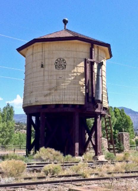
WATER TANK SPOUTS: More than you probably ever wanted to know. This posting will be more info about what I have learned this past weekend, and not much about my water tank I’m building, and based upon my findings and what I observed. On my way up to CO for the Goosefest, I stopped at the D&RG restored water tank along Hwy 160 in Southfork CO. Here was my chance to observe the real thing.

(http://i1234.photobucket.com/albums/ff403/dave2-8-0/WT-140.jpg)

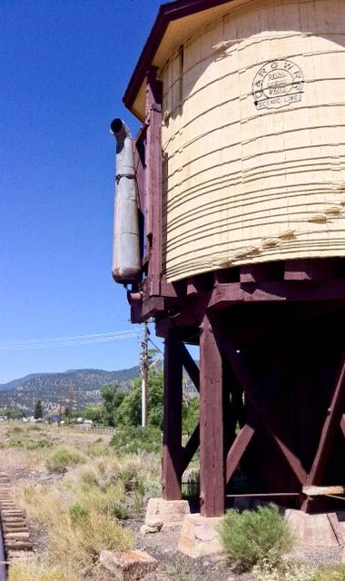
It appears that it has been well preserved, there did not seem to be any major repairs or alterations done to it. I paid the most attention to the spout and how it was hung for operations. Surprise #1… it is NOT Firmly attached to the tank! It is attached to the tank with short lengths of stout chain.

(http://i1234.photobucket.com/albums/ff403/dave2-8-0/WT-141.jpg)

Notice that the chain is slack when the spout is in the up right position. The weight of the spout is carried by the counter weights and the cables.

(http://i1234.photobucket.com/albums/ff403/dave2-8-0/WT-143.jpg)

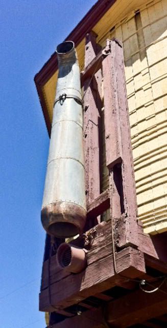
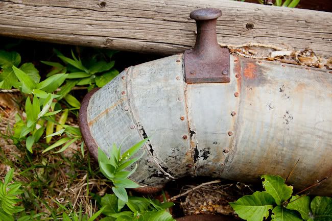
Notice that the cables on this tank are tied off to the base of the tank and there appeared not to be any counterweights attached. I believe that this was done to make the spout inoperable for preservation and to prevent vandalism. The spout is made up of 4 riveted sections and the curved discharge end. The cables for the counter weights are attached to a metal band around the upper part of the spout.

(http://i1234.photobucket.com/albums/ff403/dave2-8-0/WT-146.jpg)

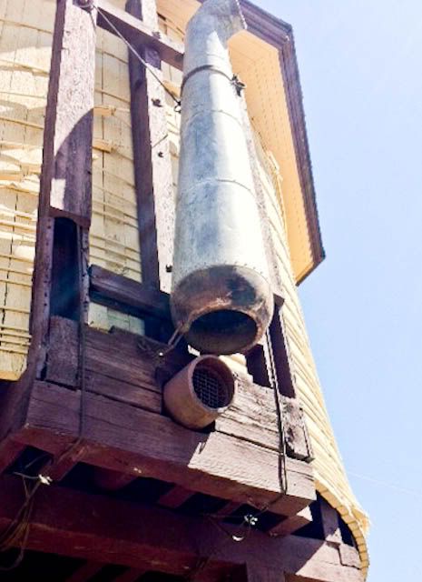
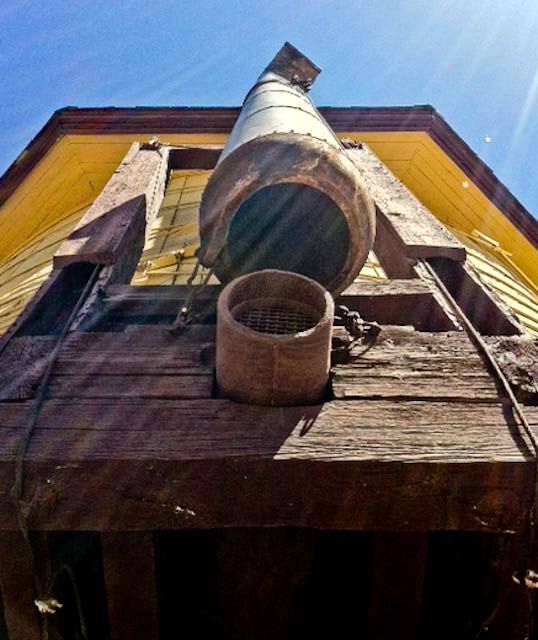
Looking up the spout. Notice how the spout is made. What I had always thought was curved sheet metal on the base appears to have rusted differently then the spout. Notice how the chains are attached to the spout.

(http://i1234.photobucket.com/albums/ff403/dave2-8-0/WT-145.jpg)

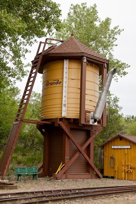
Note here that the spout hangs above the discharge pipe. Learnings from this tank. There is no pivot point for the spout. It is not hard attached to the tank. On to the working water tank at the CO RR Museum. Newly built to handle there running steam engines.

(http://i1234.photobucket.com/albums/ff403/dave2-8-0/GooseFest0007.jpg)

A great looking working tank. But on closer examination, It is not a traditional tank! The staves are only decorative, and the bands are for looks only, it appears to have a water tank inside the outer housing. Gee who would ever think of doing that. The important part is the spout and how it’s attached.

(http://i1234.photobucket.com/albums/ff403/dave2-8-0/GooseFest0008.jpg)

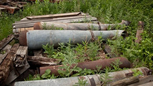
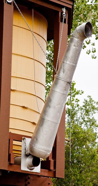
Here is the spout and works of the museum tank. Notice that it is hung and operates the same as the South Fork tank. The curved base is painted the same as the rest of the spout. There are also 4 riveted sections to the spout and the curved end riveted on. Here the chains attached to the bottom of the spout are tight and supporting some of the weight and they used chain for the counter weights. The Museums spout appears to be the same as the one on the South Fork tank. The spouts and the operating works appear to be the same. Having a VIP Pass for Goose fest pretty well gave me a no questions asked access to anywhere i wanted to go on the grounds. I love to wander the back lots of railroads and look-see at there bone yards you find some of the best stuff out back, and here was no exception, for now I’ll limit my findings to water tanks. (see my earlier post of the spouts). I’ll limit this discussion to the found spouts that I think are authentic based on the other two we talked about. SURPRISE #2. The curved base end of the spouts are a very heavy thick iron casting!

(http://i1234.photobucket.com/albums/ff403/dave2-8-0/GooseFest0161.jpg)

(http://i1234.photobucket.com/albums/ff403/dave2-8-0/GooseFest0163.jpg)

I used a dollar bill for size comparison. Notice the mounting brackets cast into the base unit. they were about 3/4" thick.

(http://i1234.photobucket.com/albums/ff403/dave2-8-0/GooseFest0164.jpg)

another base unit. I could find no casting marks or names in the castings. They hefted out to be about 50 lbs. guessing from lifting the cast end. Also note that the sheet metal part was riveted to the casting. It makes sense that they would use the castings on the part that took the most abuse in use, and have to hold up the weight of the water also. On to the sheet metal spouts.

(http://i1234.photobucket.com/albums/ff403/dave2-8-0/GooseFest0153.jpg)

It appears that all the spouts were of riveted construction.

(http://i1234.photobucket.com/albums/ff403/dave2-8-0/GooseFest0154.jpg)

And the Sheet metal joints appeared to have been soldered.

(http://i1234.photobucket.com/albums/ff403/dave2-8-0/GooseFest0165.jpg)

On the large end on this spout a wedge was used between the ends of the rolled sheet.

(http://i1234.photobucket.com/albums/ff403/dave2-8-0/GooseFest0167.jpg)

(http://i1234.photobucket.com/albums/ff403/dave2-8-0/GooseFest0157.jpg)

The counter weight attachment point was a steel band around the upper part of the spout.

(http://i1234.photobucket.com/albums/ff403/dave2-8-0/GooseFest0159.jpg)

(http://i1234.photobucket.com/albums/ff403/dave2-8-0/GooseFest0156.jpg)

(http://i1234.photobucket.com/albums/ff403/dave2-8-0/GooseFest0158.jpg)

The curved ends were typical sheet metal construction, riveted and soldered. The ones with a metal reinforcing ring have survived much better.

(http://i1234.photobucket.com/albums/ff403/dave2-8-0/GooseFest0168.jpg)

And a dollared discharge end for size comparison. There it is. More then you wanted to know about tank spouts. And I hope you learned something new. I certainly have. Now am I capable of building one for my tank? Ill save the flap valve, real staves and banding for another post.

These pics and your comments are terrific!

I’ll speak for the onlookers that we anticipate the flap valve, staves and banding.

Good idea to use a dollar to help with the scale of things.

That was a great study Dave Thanks for sharing it :slight_smile:

Dave,

Excellent study, and fantastic photos. The photos alone are worth their weigh in … I can’t afford gold. :slight_smile:

The wedge piece in one of your photos may have been a filler to make the difference in the available sheet size to roll the majority of the cone. May also have been a wear patch, we will likely never know.

Thanks for sharing, and the small differences are surely intriguing.

Bob C.

That was great stuff, and the trip perfect timing for your project back at home. Thanks oodles for posting all this, Dave!

I believe there are both cast steel and cast iron base units shown in your pics. The cast steel ones are orange rust with what looks like old white paint, the cast iron one is oxidized black, and probably an older design.

And no, I’d bet it’s not too much information for any one of us… we kinda’ go for this stuff… :confused:

Hey! On the Southfork tank, there’s a mesh indside the outlet pipe to keep birdies and rats out…