That’s clever, thanks John D.
Neato! Be sure to use a fairly close* tolerance hole. I think if tubing gets inside it will add resistance… (http://www.largescalecentral.com/externals/tinymce/plugins/emoticons/img/smiley-smile.gif)
*fairly close = snugish is the technical term. (http://www.largescalecentral.com/externals/tinymce/plugins/emoticons/img/smiley-wink.gif)
Cliff, I could not find a what I wanted in the point throw plate that met my demands, for the air drive I made. So I engineered my own replacement, and cast them my self. Tough and durable was 1st demand.
Here is mine, next to an Aristocraft Original. As you can see, MUCH thicker, slightly larger, and custom drill-able for whatever use.
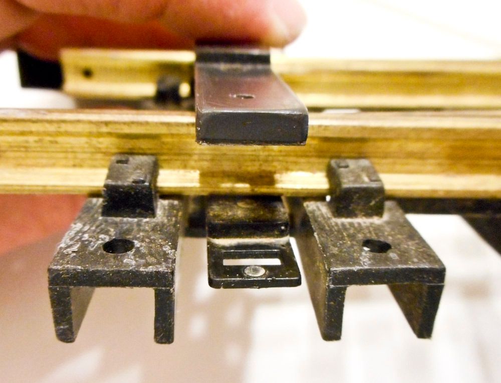
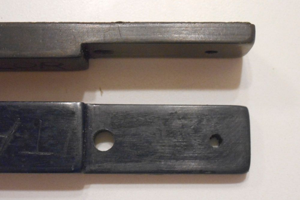
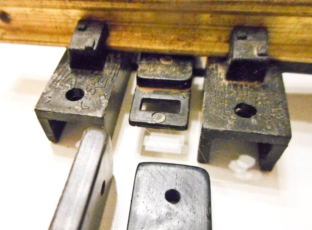
I have yet to have one of these fail in any way.
Dave, there could be a real market for these. I’d be interested in buying a number of them if available.
Not only are they fragile, but this plastic part is NOT UV protected, per Lewis Polk (and my own observations)
Regards, Greg
A chunk of brass bar works well, too. (http://www.largescalecentral.com/externals/tinymce/plugins/emoticons/img/smiley-laughing.gif)
Thanks for posting that Dave, I would never have guessed. I just looked at one of my turnouts (Train Li), and I see that there are screws going up from the bottom, through the throw plate, and threading up into the point rails. Seems like an easy replacement, at least for me. Does that connection description sound typical?
A slow-acting and sprung servo drive might not absolutely require this upgrade, but I can imagine a quick-acting air system demanding it. And if the throw plates are not UV-protected, I suppose it’s just a matter of time that they fail, with any form of operator.
Greg, was that a specifically Aristocraft lapse? Or do you think other manufacturers did similar?
Seems to be specific to Aristo. The people who made the ties were apparently different from the people who made some of the small parts. Very strange. It took a number of people testifying to decomposed throw bars to get the real story. Aristo used to replace these for free. Don’t think that’s still true with GeneratioNext.
Greg
Greg, How about I send you a couple three for you to test out and evaluate and beta test? The last thing I would like to do is sell someone something less then perfect.
Sure, contact me by private email.
this is a part that everyone will eventually need.
In my case I loop the air motor wire through the exposed end of the throwbar, so it fragile part is exposed to sunlight.
With the stock switch motor, this fragile end is covered up and will last much longer.
Regards, Greg
I received the missing parts a couple days ago, and was able to spend most of the day building and testing and commenting on this prototype.
A ways to go still, but here’s the state of things at this point.
Thanks for watching,
===>Cliffy
Nicely done. I haven’t seen those waterproof boxes with a clear cover. Where did you find them? The plastic tube surrounding the throw bar would let water in however, would it not?
Cliff, How much travel ( linear ) on the throw? And can it be adjusted? Is there an issue with the servo push rod not being fully in/out for an extended time ie. days, weeks?
Thanks Dan, and I agree about the water incursion. It will require that its entry into the box is not the low point, and that will probably mean a drain hole is needed at a low point in the tube. The next phase is hooking it to a turnout up and experimenting, and I’ll add that to the list of investigation. The box is by Hammond, purchased thru Digikey:
http://www.digikey.com/product-search/en?KeyWords=hammond%20RP1085C&WT.z_header=search_go
Dave, it was set up for about .3" of throw, but I increased that by lowering the attachment point to the next lower hole on the servo saver. I lowered the exit hole also, to reduce cable bending. I’ll measure the today and get back with a number. So, you have a choice on where to pin that joint. For adjustment beyond that, I’m hoping that the spring will take care of things. I changed the servo saver internal spring, to make it pretty squishy. The servo driver board self-adjustment feature comes into play, moving the servo until a certain amount of resistance is encountered, and sets those points as the ends of travel.
The push rod that exits the box is presently 1/16" SS cable, so it will do fine outside. I also will experiment with steel spring wire (which John C. & others recommend, see prior posts), which will rush but most likely survive for some lengthy time. But please share any thoughts you have.
Thanks gentlemen,
Cliff
Holy Moly Cliff! That is amazing! Tons of potential to do everything you could ever want. Not to mention it’s built like a brick… well, you know where I was going. Well done sir. You’re well on your way.
Looks great, Cliff. How will the local control switch throw integrate with it?
The video is gone?
Sorry Dennis, I’m replacing the video, it should be back up in a moment. (I haven’t experienced this Youtube “processing” delay before).
Thanks Randy, I appreciate it! Speaking of functionality, another thing about this Tam Valley board is that it’s supposed to run on 7-18v, AC or DC. So… for non-DCC and even non-rail-power applications, it sound’s like one could install a sprinkler or landscape lighting transformer, run a sprinkler wire bus, and tap off of that.
A nice thing about the pushbutton input is that you can have more than one (daisy-chained), so it would be easy to add that to the switch stand. Also, for the drive, at some point I’d like to pack in an RC relay receiver board (single channel), to use with a wireless transmitter. But that’s down the road.
Hi Bob, thanks! If you mean the switch stand, that would need a special version with something like a magnetic or heavily sprung throwbar coupling, so that it could momentarily work against the throwbar position, yet still follow along with it… kinda of a chicken and egg quandary. Or, just have a hidden pushbutton on the deck of the stand, and bag the contacts. I guess I was putting contacts into the switch stand to make it generically useful (without this drive). But with the relay in the drive, there would be no reason to have both forms of contacts I suppose.
In making the turnout connection, I had a number of minor setbacks, the main one being the fit of the cable within the tube. Early on this thread, Riderdan brought up the issue of play, and, sure enough, today I’ve seen how big an issue it can be. All of the servo stroke can go into pushing the cable to one side if the tube’s ID, or pulling it back against the other side (or a combination).
The other main problem is that there is friction between the nylon tube and cable. I first tried 20’ of it, and I couldn’t quite push it through to the end. Serious bummer.
So, I have some .073" ID / .125" OD tube on order (vs. the current .125 ID / .250 OD), which was the tightest affordable hard flexible plastic tube I could find. Hopefully it will take either cable or spring wire.
Anyway, on a shorter cable length, the setup did well. Todd, the travel is currently 1/2", with some going into spring tension at either end, and some going into tube slop. This is after I let the board go through its auto-adjust routine, which seemed to take all that into account. The point rails are tight in either position.
Here’s the setup, with the top of roadbed elevated to the same level as the top of the drive box.


Thanks everyone for your suggestions, comments and viewing.
===>Cliffy
An early fix was to have a return spring on the far side (of switch) handle the push (by pulling) part and the servo the pull.
Is it done yet? yer bud,
John
I can see alot of potential for your creation. I never thought of a flexible throw rod as long as the one in your photo. Great idea.