Swing keeper

Basically the part is aligned with holes wire goes thru and body snaps on wire. Print in nylon.
Swing keeper
Basically the part is aligned with holes wire goes thru and body snaps on wire. Print in nylon.
Thanks John, I saw something like that on the Dubro site called the E/Z Link, and it’s good to know the proper term for it.
You’re right, this would get rid of the E/Z Connector; but I’d still have to use the clamp to transition from cable to rod. If someone wanted to use rod (like, piano wire) to go all the way to the throw bar, this would be the ticket. I’m starting with the cable, for its decreased likelihood of kinking (vs. rod/wire).
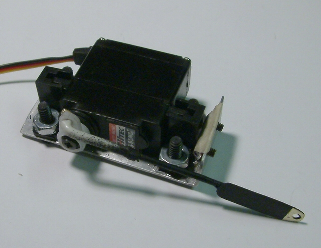
An issue has surfaced with the servo saver. Its spring is so stiff that any forced rotation just back-drives the servo; it seems designed to only remove transients sharp enough to break a servo tooth. I was expecting something far springier, to allow at least some point movement without motor backdriving. So I’ll try to replace the spring…
[edit]
I replaced the spring and now there is around 1/4" of sprung saver rotation (either way from center) before the motor backdrives. That’s more than the point movement, so I guess that’s ok. This might change in a couple weeks though, when the printed parts come in and the components are assembled to a turnout for real testing.
I just ordered the printed parts, so I guess my build project will be on hold for a couple weeks until they arrive. Here’s the bits:

What I’m messing with has a lot of shortcomings, and there are many other ways to skin this cat. So please feel free to share your views & ideas on what you think a switch drive should be, and keep the conversation going.
Thanks for viewing,
Cliff
Spring wire won’t kink without 2 pairs of pliers making it so… Especially with in a cable housing.
I thought the remote control afforded close placement of the motors, avoiding long throws required for kinks.
I get my wire in 36" lengths out of tubes.
I think you are over engineering the mechanical part. Thus making that connection clumsy. That’s all.
Your friend,
JC
A nicely placed boot heel can disable a spring wire in a jif, I would think. But, you have experience with it, so I won’t dispute you there. All I’m saying is that multi-strand cable is less susceptible – though you can kink it as well.
Main thing, allow the user to decide, and make things easily replaceable (cable, wire, sheathing-tube). Long runs and circuitous paths argue for cable, I’d think. But if I was wrong, I’d like the opportunity to swap out cable for wire. Or vice versa. And if I shove a shovel in the wrong spot, I’d like to be able to re-run the line without much fuss.
I get my cable in 50’ or 100’ lengths in a coil. Cheaper shipping.
(http://www.largescalecentral.com/externals/tinymce/plugins/emoticons/img/smiley-tongue-out.gif)Just kidding!
[edit]
John, as we talked about on the other forum, it’s nice to keep the options open. Testing with both cable and wire seems like a good idea. I’m looking at Mcmaster (not the cheapest place, but one of the most prolific), and their 316SS spring wire is pretty pricey. Where do you get yours, and what’s the material?
While I’m waiting for Shapeways parts, here’s a small update on related matters.
Based on the comments received, I’ve re-booted the switch stand design and started around just the contacts. Off-the-shelf 5-10A adaptable switches are elusive and pricey. However, Todd B. and Greg E. encouraged me to consider going homegrown, so I’ve taken their advice.
Long ways to go, but here is how things are shaping up. This is a bottom view, showing DPDT contacts of 1/16 x 1/4 bar, held down by “printed” keepers and secured with the same screws that would clamp the wire.

The wiper is the same material, sprung against the contacts with two 1/8" SS springs. The thickness of the wiper keeps it in its pocket, though bent-down ends would insure it.

The orange-ish block is the wiper carrier, and also the thing that the rotary or harp switch stand would be thrown by. I’ve not yet put in the throw bar that would move it, but I’m leaning toward bent 1/8" rod that could be trimmed to suit. The six contacts hold down the carrier and retain the wiper. At least that’s my story, and I’ll stick to it right up until assembly day. 
Since a switch drive might not have a lot of excess force to move the carrier (and the stand with it), low mechanical resistance is good. That’s why I went with springs, which can be altered to repeatably achieve a specific force, vs. bent brass bars which might be more subject to inconsistency. At least that’s what I’m comfortable starting with.
The connecting ties are sized for a 4" harp stand clearance. The ties would be trimmable, if one wanted to reduce this clearance.
Speaking of switch drives, I received the box a couple days ago. Here’s how it sizes up with, from left to right, the Aristo,ProDrive, and Piko (& LGB) machines.


Thanks for viewing,
===>Cliffy
Here’s the “platform” with non-shorting contacts (thanks to Todd B.), a 3/32" rod throwbar, and saddle-type clamp for the rod.


The platform is 2"x2"x.5" at the moment. Kinda big, I know…
===>Cliffy
Been tweaking things more, and resurrecting the stands and targets after all the surgery. Main efforts were centering the stand over the platform, and using 3/32 tube for the targets (after handling some real 1/16" tube, and comparing the SVRR stand).


The nagging thing I have at the back of my head now is, why not try to make a ground throw out of this? Instead of making it an indicator-only, why not try to make it an operator, as an option? Or both? But then, I try to remember the issues with that, such as:
[LIST][*]A ground-throw operator needs some sort of holding means, like an over-center spring or a detent or something, to keep the point rails secure to one side or the other.
[*]It also should use a spring somewhere in the throwbar linkage.
[/LIST]
The indicator stand doesn’t need either of these, because it’s just following the switch drive & point rails. But ideally, the platform would be usable as either an indicator or and operator, “slave” or “master,” depending on whether there’s a switch drive present or not.
Thoughts? Opinions?
===>Cliffy
Cliff, you might check out this thread… http://www.largescalecentral.com/forums/topic/12687/search/view/page/1 Scroll through it…
Bruce Chandler built his own groundthrows, or switchstands, as he calls them, this seems to be the only extant thread that describes the process. If this intrigues you, get in touch with Bruce, I’m sure that he will fill in the blanks.
Hehe. I think my stuff is a bit more primitive than what Cliff is working on.
This is an interesting topic,but if I can help I will.
Thanks for pointing that out Steve. Wow, what nice stands, Bruce! And quite straightforward in construction. They remind me of the SVRR ones, though yours cost only a fraction of theirs I’m sure.
For the benefit of others, here’s Bruce’s build page:
http://jbrr.com/switch-stands.html
Bruce, about your piano wire. It looks like you primed/painted it, correct? I suppose that means it’s hard to get in SS? Also, do you recall what gauge you used? Lastly, does that bend pattern achieve enough springiness, and work even though there’s gravel nearby?
Thanks again both,
Cliff
[edit] Bruce, I like how your (and SVRR’s) stands lock. With the spring, you get a guaranteed tension on the points. So far though, I’ve been steering away from that approach because 3d printed parts (for the handle and the lock-disk – your penny – at the top) wouldn’t hold up nearly as well. But, maybe there’s a way for me to print just those bits in brass, for a lockable version… hmmm…
Cliff, no, the wire typically does not have anything done to it; although it will rust outside…even the stainless stuff seems to rust for me. I might have touched it with some boiled linseed oil when I did the ties, but it’s only because I’m sloppy. Though looking at that picture it DOES look like I painted it. Maybe just to tone down the throw bar or something.
I don’t recall the wire size at all. You don’t want it too thin or it won’t hold the points. Too thick and it’s too hard to bend. Just right, I guess. (http://www.largescalecentral.com/externals/tinymce/plugins/emoticons/img/smiley-embarassed.gif)
The penny is easy enough to cut with a Dremel, so I’m not sure you need the precision and cost of 3D printing. (http://www.largescalecentral.com/externals/tinymce/plugins/emoticons/img/smiley-foot-in-mouth.gif)
Preserving the piano wire should not be a worry. It will last longer than I will, and its easy to replace.
All good advice, thanks guys. I’ll have to just get some and play around with it!
About that rotary switch stand. I’ll come clean, and admit I messed up: the legs are turned the wrong way. I’m sure some of you caught that. I did find a very few examples of legs oriented the way I have them, but by far, most have the legs spanning the space between the ties. Which totally makes sense.
Here’s an example of one going “my way,” basically a thin frame that mounts on only one tie:
http://www.rmweb.co.uk/community/upl…7177_thumb.jpg
Another, for a low stand, that was planted on a steel plate to make it work:
http://www.johnnyspages.com/mt_gambi…itch_stand.jpg
But, those are exceptions. So I was going to remodel the rotary stand, to fix this oversight. Unfortunately, to keep the electrical bits underneath the same as the harp, I’m not finding a clear design path for that, because of the off-center rotary motion of the pin that moves the connecting bar.
So for now, I’m going to keep heading the way I was. But at some point, I think a proper rotary, with the off-center connecting bar linkage, will need its own special platform design (vs. the harp, which is centered and symmetric throughout).
Oh well. The bright side is, ECLSTS next week!
===>Cliffy
Tsk Tsk… left hand on the pin, right on the lever…

Wear your galoshes. It’s wet out!
Cliff. It looks that you would use the Throw plate for the points, to move the rotary on the switch stand. Note that the very end of the throw plate on Aristocraft switches is very fragile when brand new, and gets worse within a few months out in the weather. Some just brake off to be ornery.
Could be a concern for your design.
Thanks John… (http://www.largescalecentral.com/externals/tinymce/plugins/emoticons/img/smiley-cry.gif)
You know, that’s a mighty fine example of an illuminated rotary, hmm…
Dave, yes I was heading that direction, because I’m relatively inexperienced and that’s the only method I’ve seen. Can you point me to a a better “generic” method? Perhaps bond an adapter of some sort to the throw plate?
The bad news was that though the Shapeways parts came in Friday, 2 parts were missing. So the switch drive project is on hold for 2 more weeks.
The good news is that my local (“DoitBest” type) hardware store had the spring wire assortment, within their K&S display. So I was able to get a nice selection. Off to find a “swing keeper,” thanks John.
If you can’t find a “swing keeper” a short lenght of wire insulation or heat shrink tubing can work…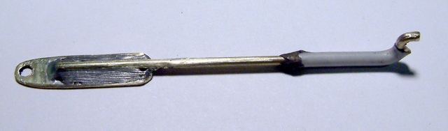