Before I make a comment, remember, I have no idea what I am talking about. Whenever I set my next loader up out in the timber, it will be my first (http://www.largescalecentral.com/externals/tinymce/plugins/emoticons/img/smiley-tongue-out.gif)I don’t think the adjustments were used to support the weight of the loader during operations. Once set where they needed it, I believe they used the adjustments to simply level the loader and then they tightened the turnbuckles to hold the legs in place while they loaded logs. I would bet, they actually relieved the stress on the adjustment screws so they would not get damaged or damage the top of the legs. John, I do think you are correct that they did not drive pilings, but I’m not sure.
So if the supports are just sitting on top of the soil, what keeps them in place? Why doesn’t the thing fall on its nose when it picks up a log?
just asking for a friend…
Found another model that did have a metal cap:

Found this quote in a document written by Surry Parker in 1908 (kind of weird text: [link]):
guarantee this machine can be moved from one set-up to another and made ready to
skid and load logs inside of five minutes.
That certainly sounds like the supports are not being driven into the ground, eh?
Jim Rowson said:
So if the supports are just sitting on top of the soil, what keeps them in place? Why doesn’t the thing fall on its nose when it picks up a log?
just asking for a friend…
Jim, The shear weight of all the equipment sitting behind the pivot point of the boom would act as a counter weight to keep it from tipping. Just the water tank alone (with water in it), sitting on the rear of the platform would allow the loader to pickup a large log. If they attempted to pick up a log that made the rear of the loader lift off the ground, they would simply add ballast to the rear like more water in the tank makeshift weights, etc. Again, I’m guessing as to what they actually did, but this is a logical option. They may have even driven some small pilings in the rear and tied the rear down with cables or they could have simply laid some logs at the rear and cabled the loader to them. A lot of options that would be much quicker than driving pilings.
Jim, Great job on your build(https://www.largescalecentral.com/externals/tinymce/plugins/emoticons/img/smiley-laughing.gif)
I know you didn’t ask but, here is my take on the S-P loader(https://www.largescalecentral.com/externals/tinymce/plugins/emoticons/img/smiley-foot-in-mouth.gif)(https://www.largescalecentral.com/externals/tinymce/plugins/emoticons/img/smiley-laughing.gif).
The leg timbers were not driven into the ground, they were legs only and probably set on some wide blocking so they wouldn’t dig into the ground.
The screw jack lift asemblies were mostly used to raise and lower the loader on and off of its flat car transport.
The car was spotted in place then the timber legs were lowered and the screw jacks were used to raise it so the flat car could be removed. It was either left at this height or possibley lowered or raised so the empty log cars could pass through/under depending if they were flats, skeltons, or dis-connects.
Once the height was established the turnbuckles were tightend creating a clamping effect. The bottom of the leg pulled slightly inward and the top slightly outward creating a wedging effect that helped the clamping action.
The stabilizer lines were then ran out to trees or stumps and tightened . The rig was as stable as it was going to get.
As to wheather the screw kacks were backed off or left snug is pure speculation, there is arguments for both cases. Anyway you look at it those leg timbers were probably replaced at pretty regular interivals.
Remember this machine was a blow and go system once set up they may have only loaded one or two cars before moving to the next landing. Which was easier, moving the loader to the logs or dragging the logs to the loader??
Point being the loader probably wasn’t in one place long enough to worry a lot about stability and movement.
Counter balance effect was well pointed out by Dan.
In going back and looking at your build I see you included the boom mast top hold down. This sometimes isn’t modled. The original SP loaders didn’t have one and this led to some fast field engeneering to keep the machine together. That iron strap that holds/guides the mast top swivel could jump up and off under the bouncing and bucking of log loading leading to an oh-oh moment. Two solutions are documented; SP came out with a iron strap tie down on their later machines and Argent Lumber (one of the first and longest users of the SP loaders) came up with the in the field solution that you modeled, the 4x4 with rod tie downs.
Here is a picture of one I built in O scale about 30 years ago, note it doesn’t have the tie down.

Wow, thanks Rick! Lots of good info that sounds pretty right to me. Very helpful.
Nice model!
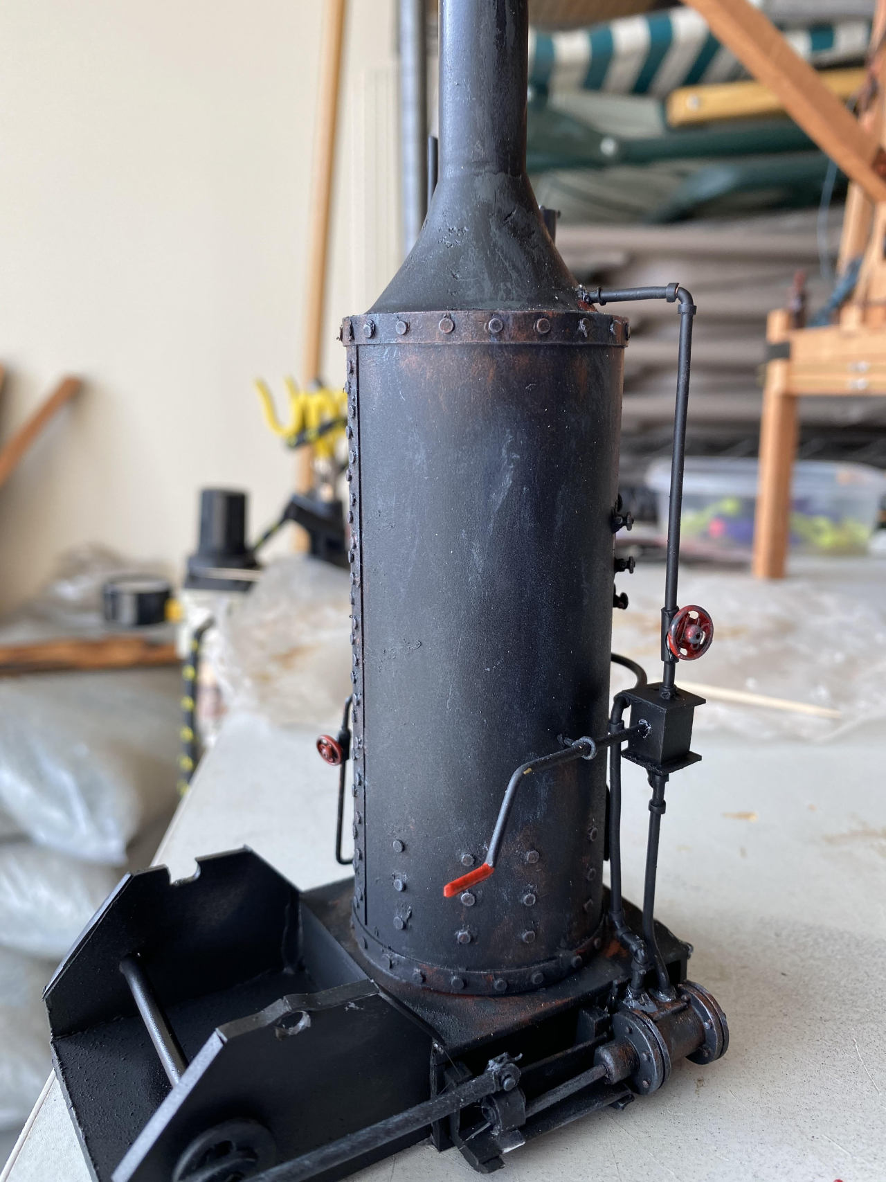
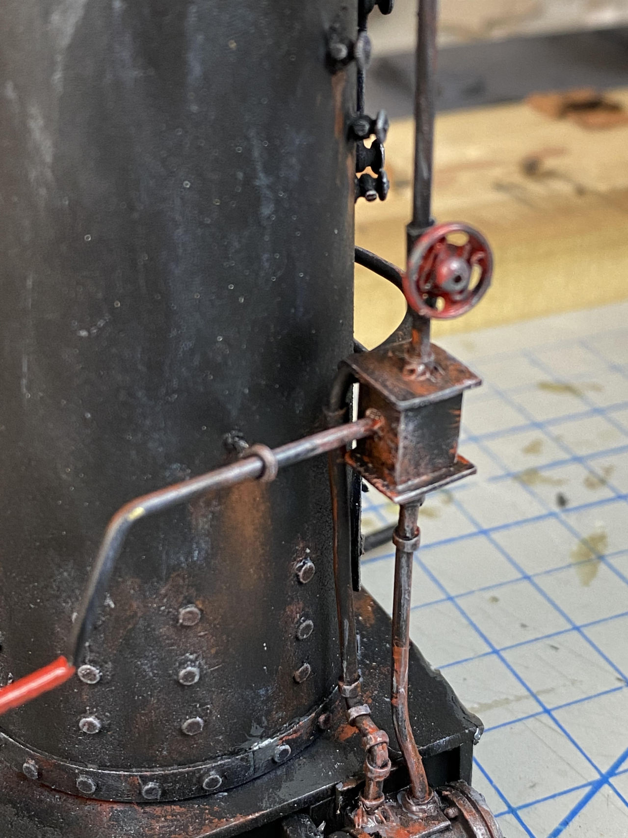
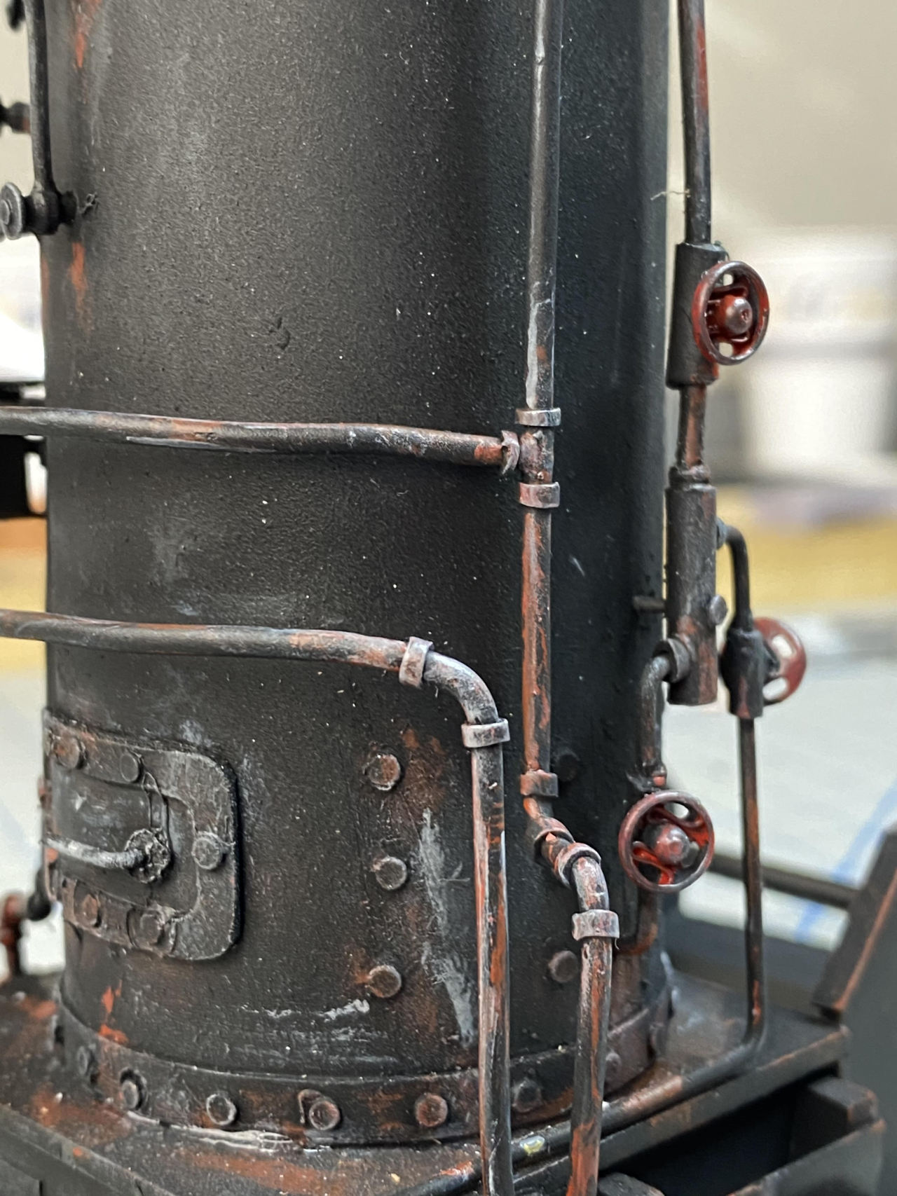
Got the piping painted and attached as well as some of the drum assembly.
Raw painting:
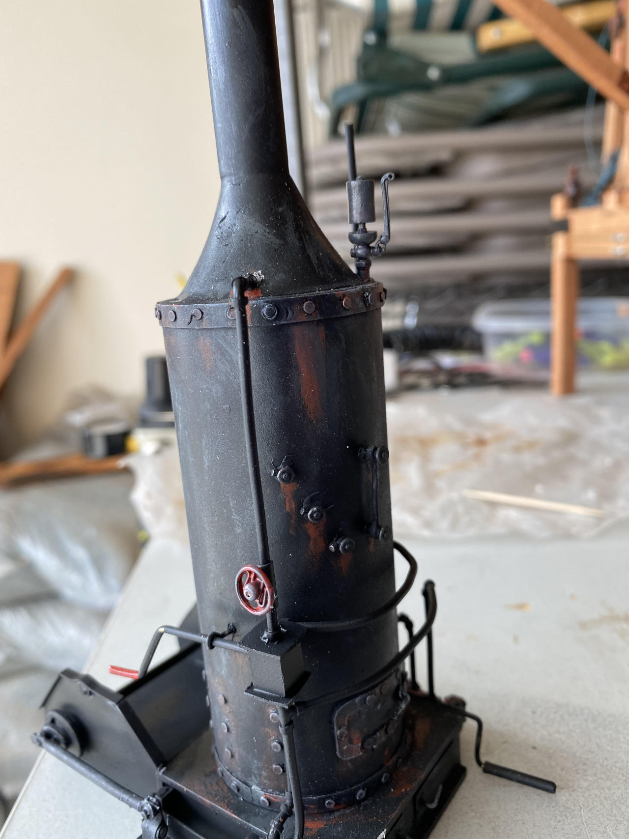
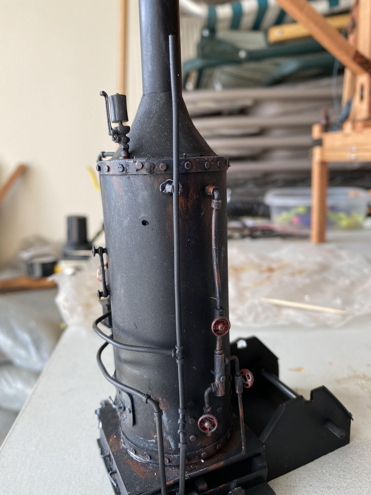
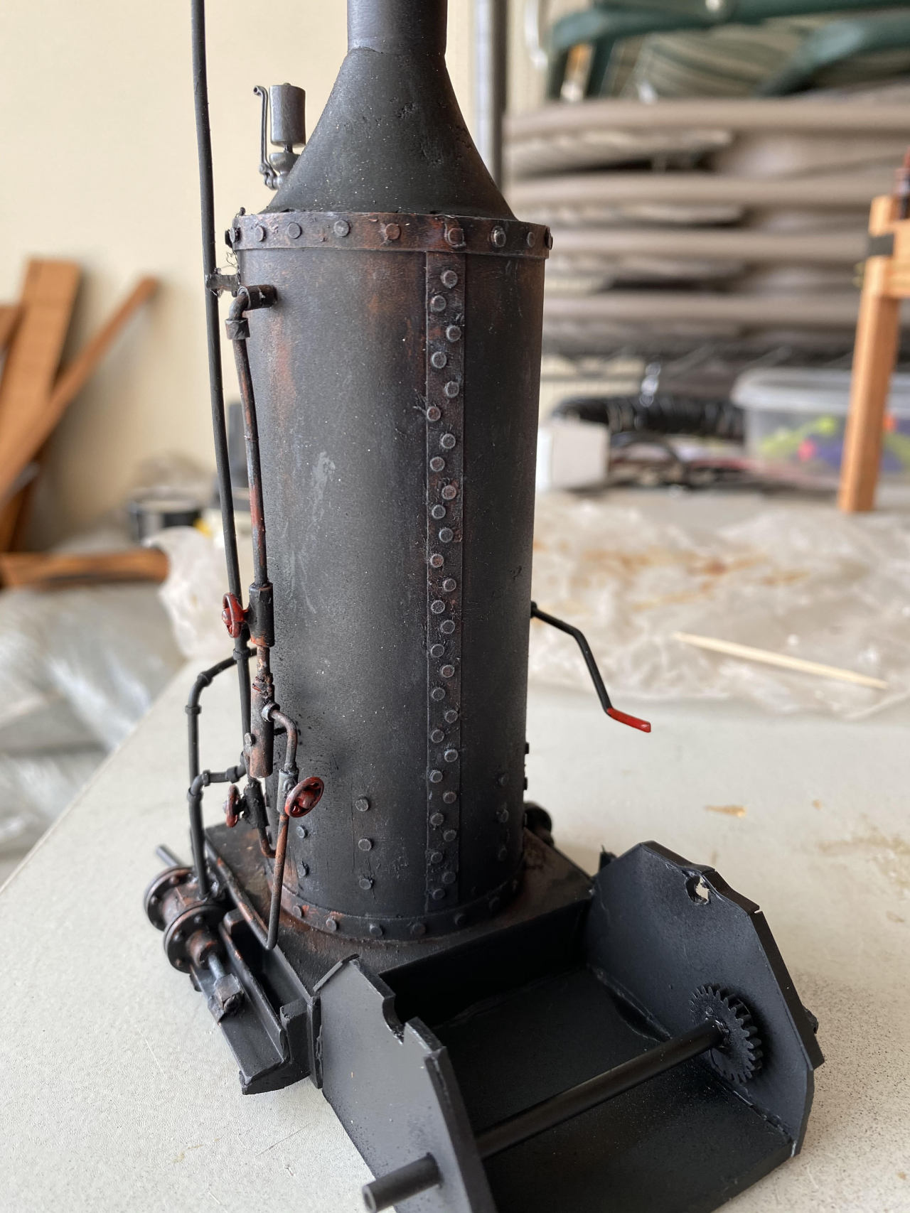
Weathering:
Cheers!
Excellent work Jim.
Jim, this feels like deja vu (https://www.largescalecentral.com/externals/tinymce/plugins/emoticons/img/smiley-surprised.gif)Oh, I forgot, you have done this once before (https://www.largescalecentral.com/externals/tinymce/plugins/emoticons/img/smiley-wink.gif)Great work. Certainly looks like practice makes perfect.
Um boss?
This picture confuses me;
Down here at the bottom, the drive from the cylinder seems to be attached to the valve box instead of the piston rod, ya wanna check into this please. Or 'Splain it to me, please.
Pickin’ the nits, because somebody must.
Well, I’m not sure that I can interpret all those names correctly (my ignorance, not poor use of names). The thing on the right down there is the piston (in my head) and there’s a rod that comes out of it that is driven by the steam (and as it returns it pushes the exhaust out of the piston). That rod then goes to some kind of linkage that connects it to yet another rod that goes to the shaft, turning the linear motion into circular motion. The linkage is meant to be held in position by sliding along the L shaped guide.
My terminology is pathetic I’m sure but that was what I was thinking.
I tried to copy what I saw in Rick Marty’s 2019 Mike build of a crane [link] (though mine is a pale imitation):

Uh oh, dare I go where only fools dare tread?(https://www.largescalecentral.com/externals/tinymce/plugins/emoticons/img/smiley-surprised.gif)
Well compared to a locomotive it appears upside down… Pic from Wiki (for terms)

In your pic, there is only one guide, so the crosshead is the white thing connecting your drive links and I don’t know where they hid the valves…
I don’t remember seeing an offset connection before, I included the more modern single guide pic to show what I think is correct; with the piston rod and the connecting rod pin in line. Seems offset would wear out bearings.
imho, see very small humble … because one never knows what will hatch in the backwoods.(https://www.largescalecentral.com/externals/tinymce/plugins/emoticons/img/smiley-wink.gif)
Thanks for Splainin’
Judging on the 10 inch rule!(https://www.largescalecentral.com/externals/tinymce/plugins/emoticons/img/smiley-cool.gif)
S’all good, John. Nice diagram for a locomotive drive.
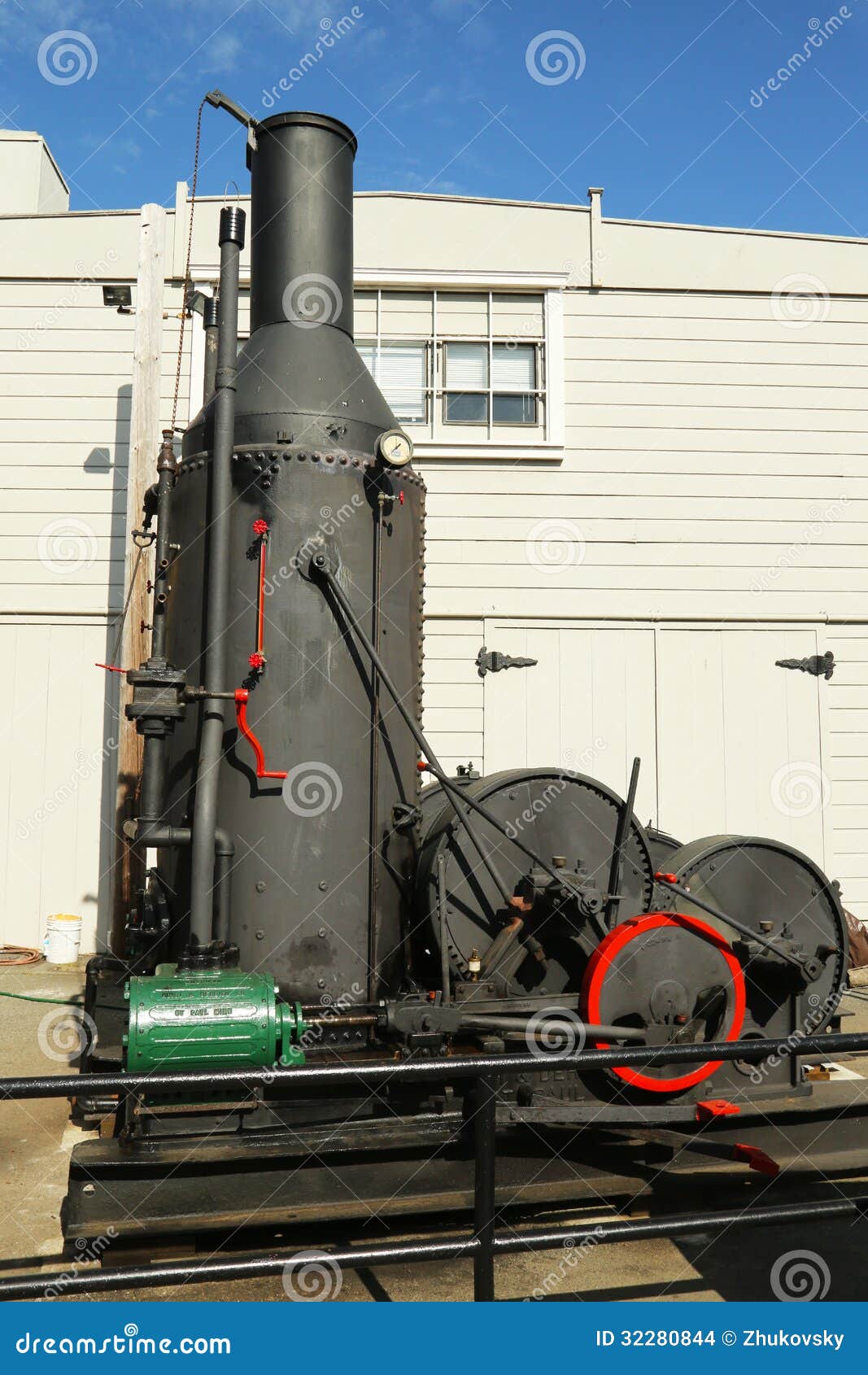
Here are a few things I found in google image search. They all seem to agree with you that the linkage should be inline and not offset. Next time, maybe…
I won’t tell, if you won’t.
Looks like I got you in trouble Jim, Sorry about that(https://www.largescalecentral.com/externals/tinymce/plugins/emoticons/img/smiley-embarassed.gif).
The Loader I built for the 2019 Challange has no valve gear modeled, along with a number of other things(https://www.largescalecentral.com/externals/tinymce/plugins/emoticons/img/smiley-foot-in-mouth.gif) It was a build challange and we only had X amount of time to complete so some things were left off. Besides all I hear around here is the quote about the 10 foot rule, sure, try to use it just once(https://www.largescalecentral.com/externals/tinymce/plugins/emoticons/img/smiley-foot-in-mouth.gif)(https://www.largescalecentral.com/externals/tinymce/plugins/emoticons/img/smiley-laughing.gif)
John is right the valve rod has to be in line with the valve rod guides. As to where the valves are, they are located in the valve chest that is inboard of the cylinders. The intake and exhaust pipes normally attach to the top side of the chest, and the valve rod is usually ran from an eccentric on the inside of the crank wheel tp guides and to the valve chest. You can see this clearly in the first and third picture that you just posted.
Here is a picture of the crank, valve rod, valve chest, and piston cylinder, with linkage that I built some time ago. This is a American Hoist and Derrick design that I copied for this hoisting engine. You can see the second rod coming from behind the crank wheel going to the valve rod and its guides.

In this picture of the Lidgerwood design you can pretty clearly see, on the far cylinder, the valve rod and its guide. This valve chest location and rod from an eccentric on the crank is pretty common across the board for “Donkey Engine” design.

Again I apologize for misleading you.
" It’s still a good build Jim"
I am not complaining. Thanks for the thorough explanation. Next time!
Don Watson said:
Excellent work Jim.
Yeah Rick but perhaps you are being too picky? He sold Doc Watson on his project so far !
Right ?
This post has been edited by: Rooster
Rooster ’ said:
Don Watson said:
Excellent work Jim.
Yeah Rick but perhaps you are being too picky? He sold Doc Watson on his project so far !
Right ?
I could be mistaken but I don’t think I was being picky about anything(https://www.largescalecentral.com/externals/tinymce/plugins/emoticons/img/smiley-wink.gif)(https://www.largescalecentral.com/externals/tinymce/plugins/emoticons/img/smiley-laughing.gif)
This post has been edited by: Rooster
If it makes any difference, my nits do not feel picked…
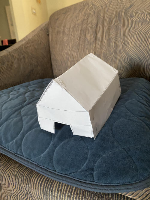
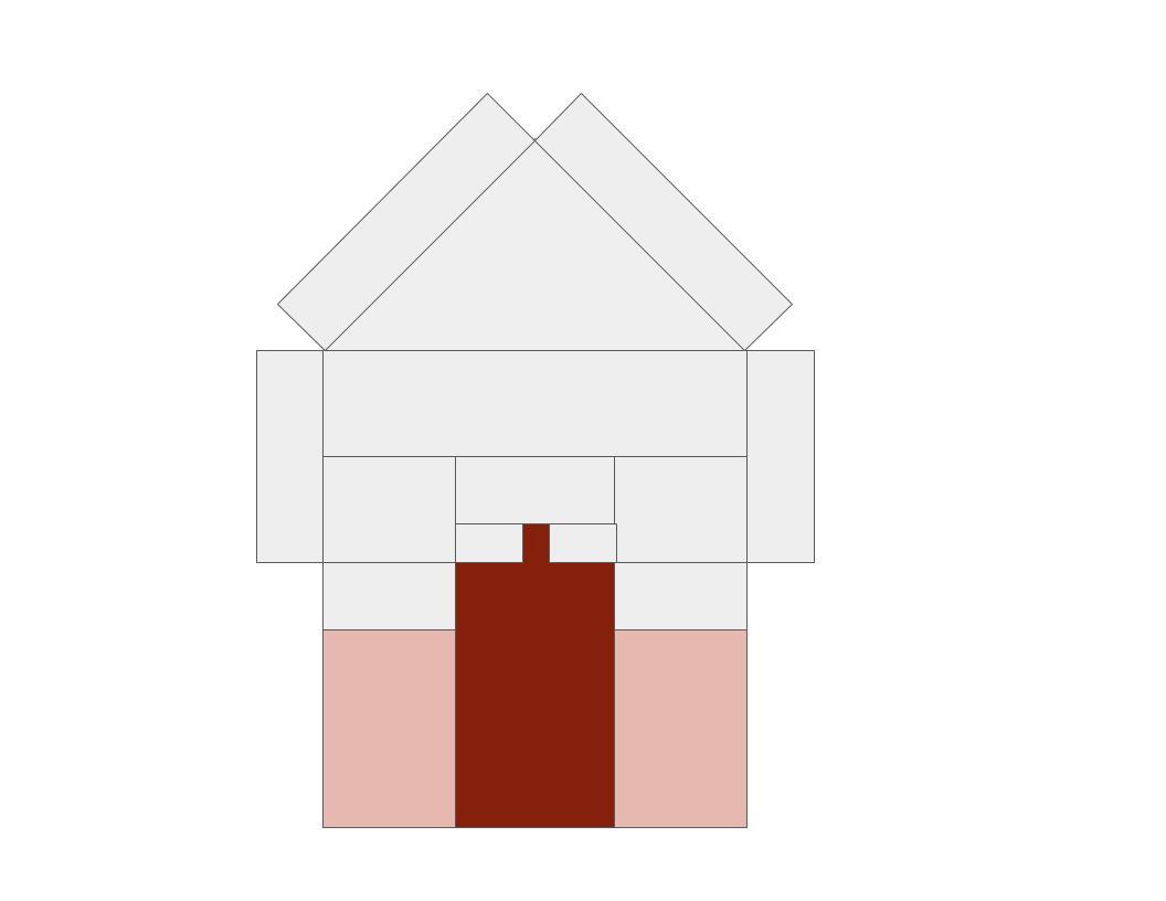
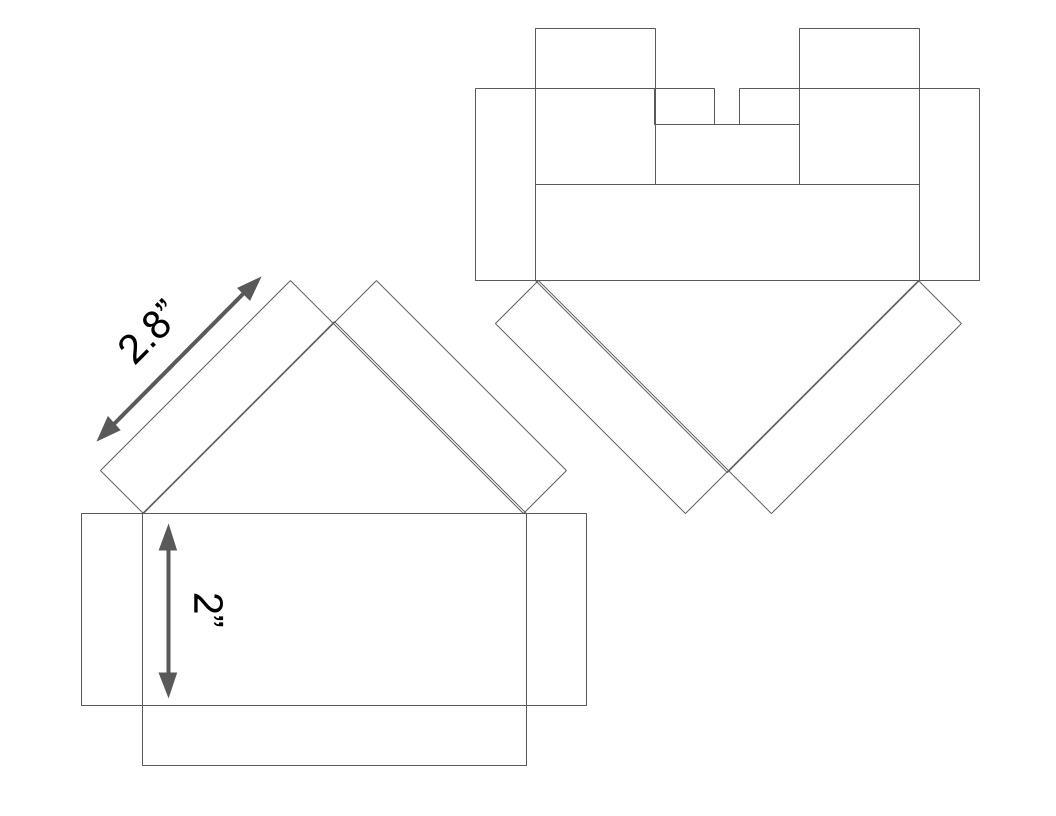
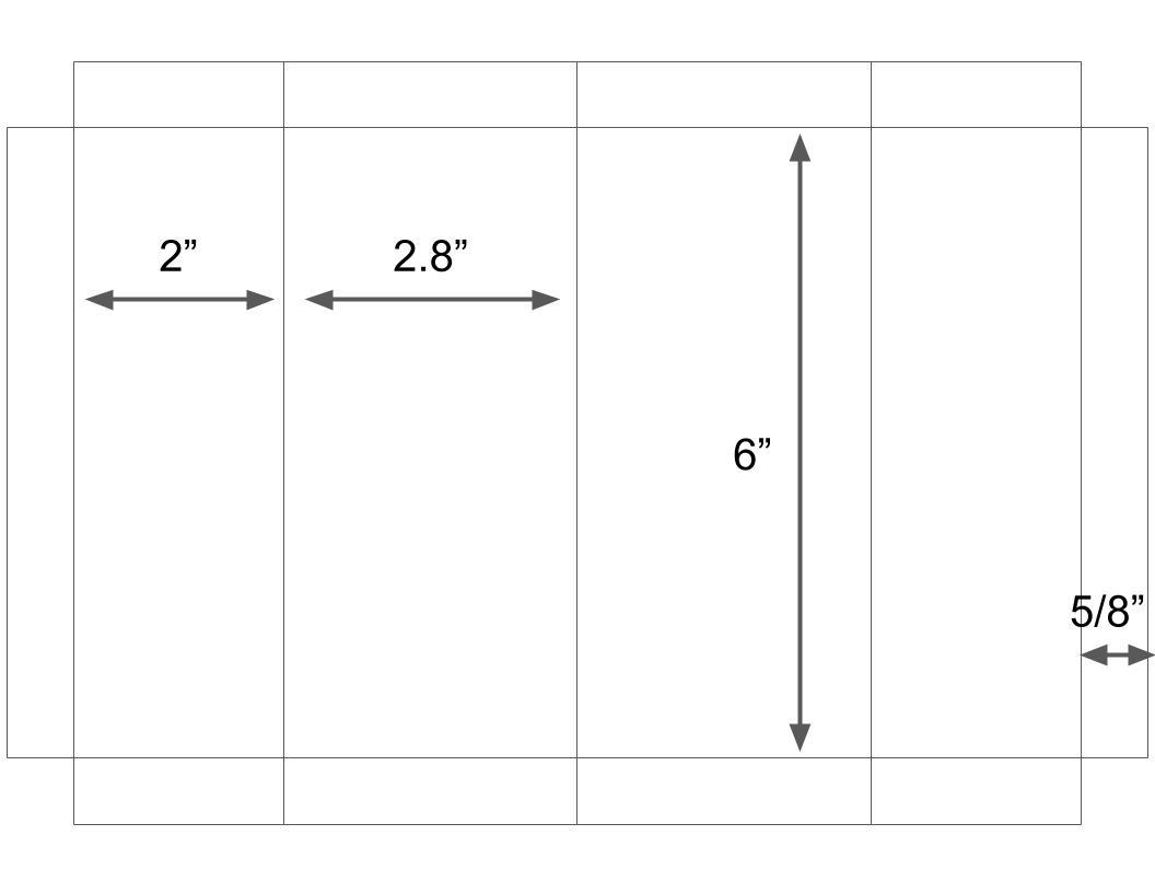
Getting started with tent cabins. I figured the first step is to get a a sewing pattern for the tent part. Here’s a first cut at it. My sewing partner is telling me that I need 5/8" to form the edges. We’ll see how this works.
After printing and tacking together:
