Hmmm. And here I thought I was copying your methods…
Jim,
Here is a shot of the piping on the Marion Shovel I built about 10 years ago (wow, doesn’t seem that long ago) but anyway it shows the nuts on the wire piping that I am speaking of. The piping is brass rod with sections of Styrene tubing and hex nuts slid onto the rod. Some of the other piping that looks black is 12 or 14 gauge electrical wiring with the nuts slid on, everything is held in place with CA glue. If you use electrical wire, 12 or 14 gauge “Romex” be sure to cut off the clear coating that covers the wires as it won’t accept paint.

Wow, amazing mechanical detail (http://www.largescalecentral.com/externals/tinymce/plugins/emoticons/img/smiley-foot-in-mouth.gif)
You are amazing, Rick! That is truly impressive.
Rick Marty said:
Jim,
Here is a shot of the piping on the Marion Shovel I built about 10 years ago (wow, doesn’t seem that long ago) but anyway it shows the nuts on the wire piping that I am speaking of. The piping is brass rod with sections of Styrene tubing and hex nuts slid onto the rod. Some of the other piping that looks black is 12 or 14 gauge electrical wiring with the nuts slid on, everything is held in place with CA glue. If you use electrical wire, 12 or 14 gauge “Romex” be sure to cut off the clear coating that covers the wires as it won’t accept paint.
WOW (:
Great stuff!
The tent houses are cool too. Most of the original cabins at the old mining camps I’ve seen, started out as wood-framed tents. If the mines went bust quickly, they could take down the tent and move on. But if it lasted, then they’d put boards over the tent and turn it into a cabin.
Jim Rowson said:
You are amazing, Rick! That is truly impressive.
Jim,
The man cannot even maintain a wheel barrow tire ! He clearly has issues!!
(https://www.largescalecentral.com/externals/tinymce/plugins/emoticons/img/smiley-cool.gif)
Fer Christ’s sake, somebody buy this kid an IPhone 11.

Rooster ’ said:
Jim Rowson said:
You are amazing, Rick! That is truly impressive.
Jim,
The man cannot even maintain a wheel barrow tire ! He clearly has issues!!
ROFLMAO
(https://www.largescalecentral.com/externals/tinymce/plugins/emoticons/img/smiley-cool.gif)
Finally worked up the oomph to start rebuilding the steam engine for the log loader. A couple of pictures for proof:
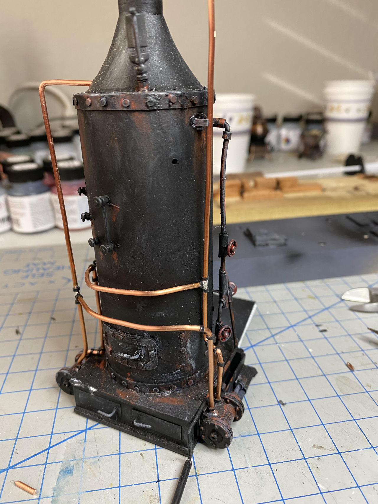
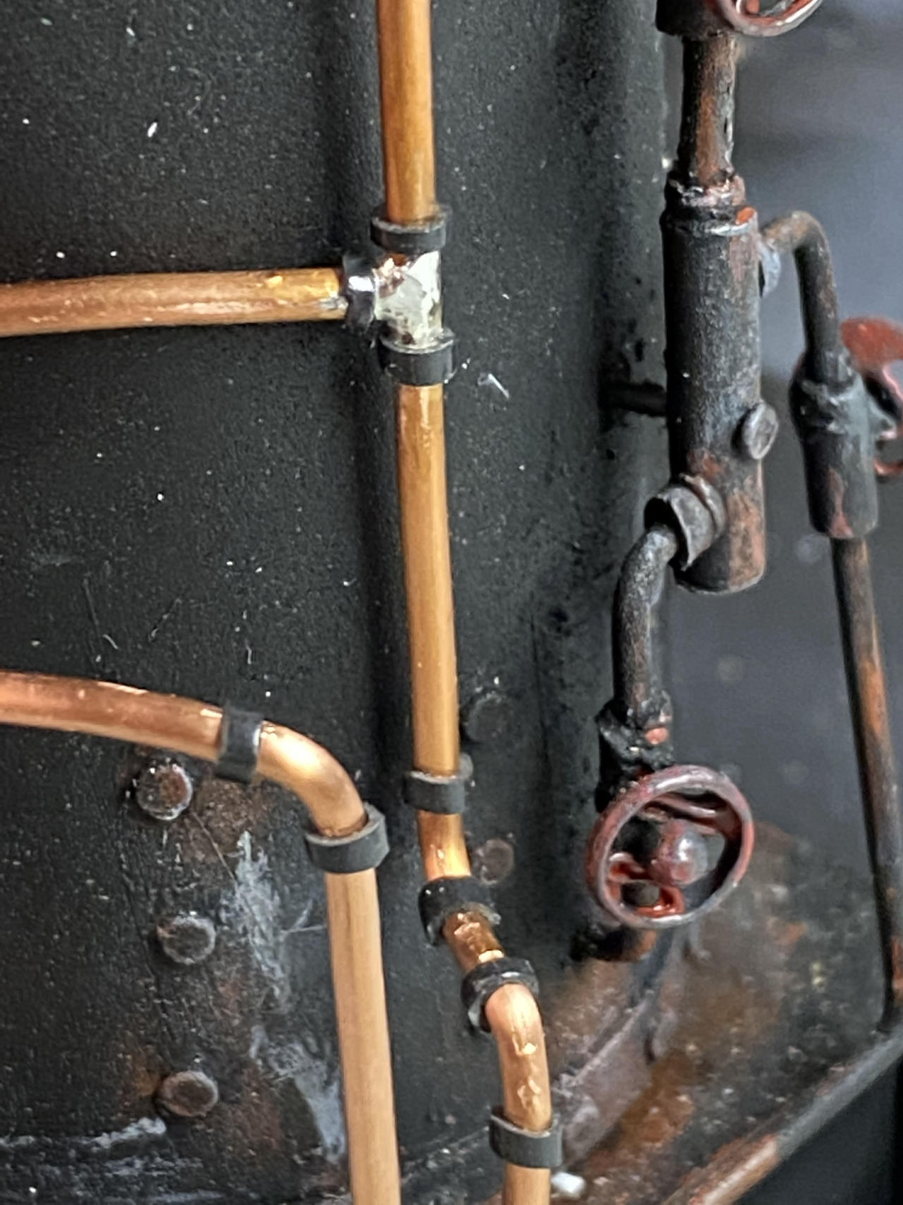
Looking good as new, Jim.
Well tweeked piping Jim. Do you hire out or maybe you could create a howto (https://www.largescalecentral.com/externals/tinymce/plugins/emoticons/img/smiley-wink.gif)
(https://www.largescalecentral.com/externals/tinymce/plugins/emoticons/img/smiley-cool.gif)
Nice work on the pipe
Started painting the pipe for the steam engine and while the primer was drying, made some progress on the strapping for the pilings:
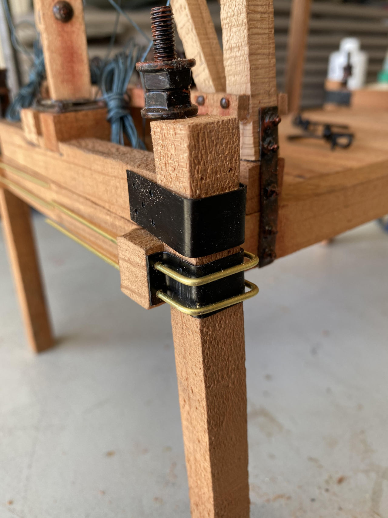
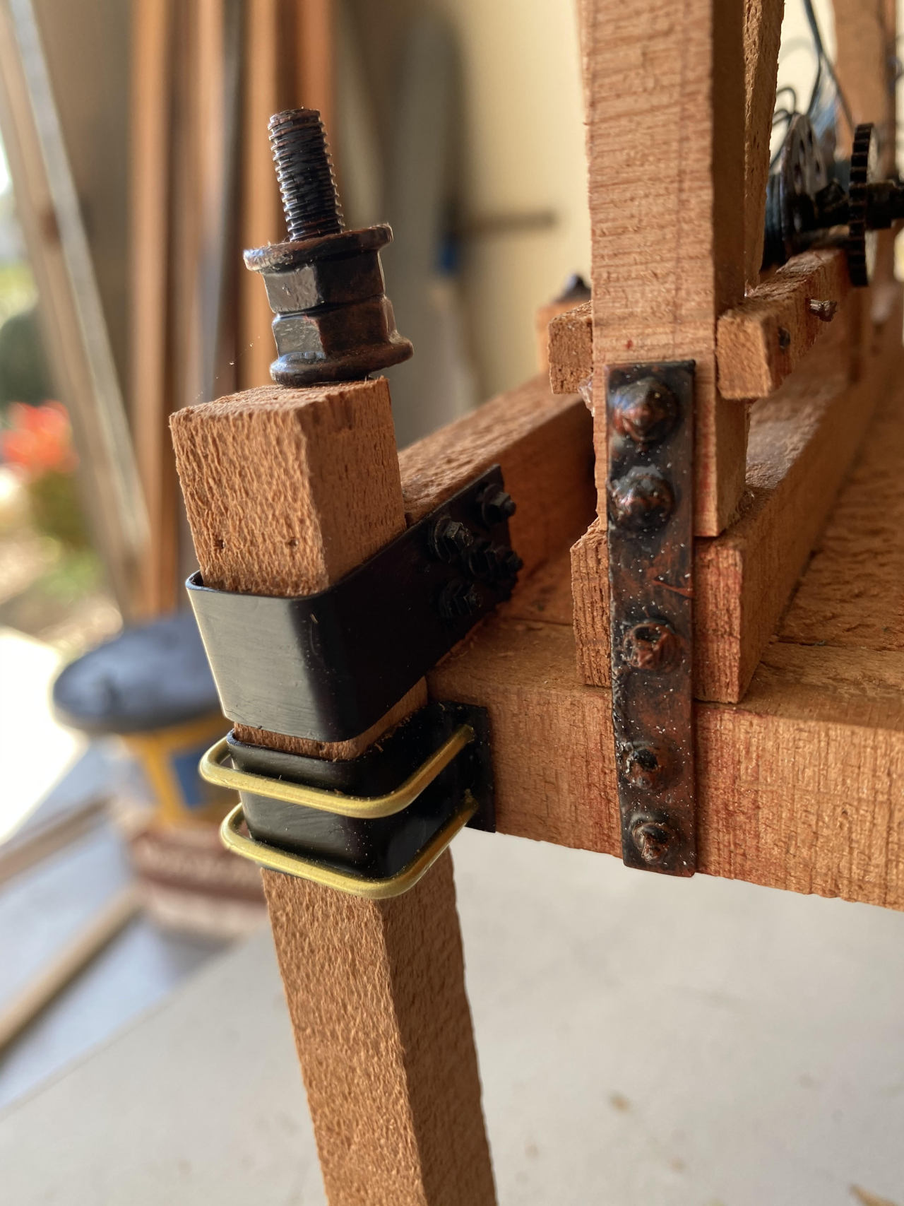
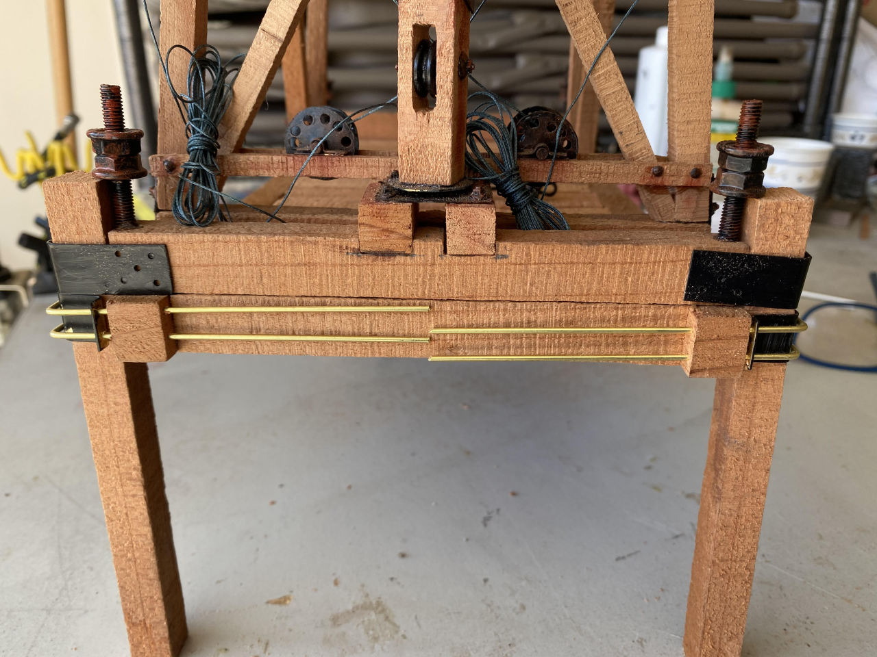
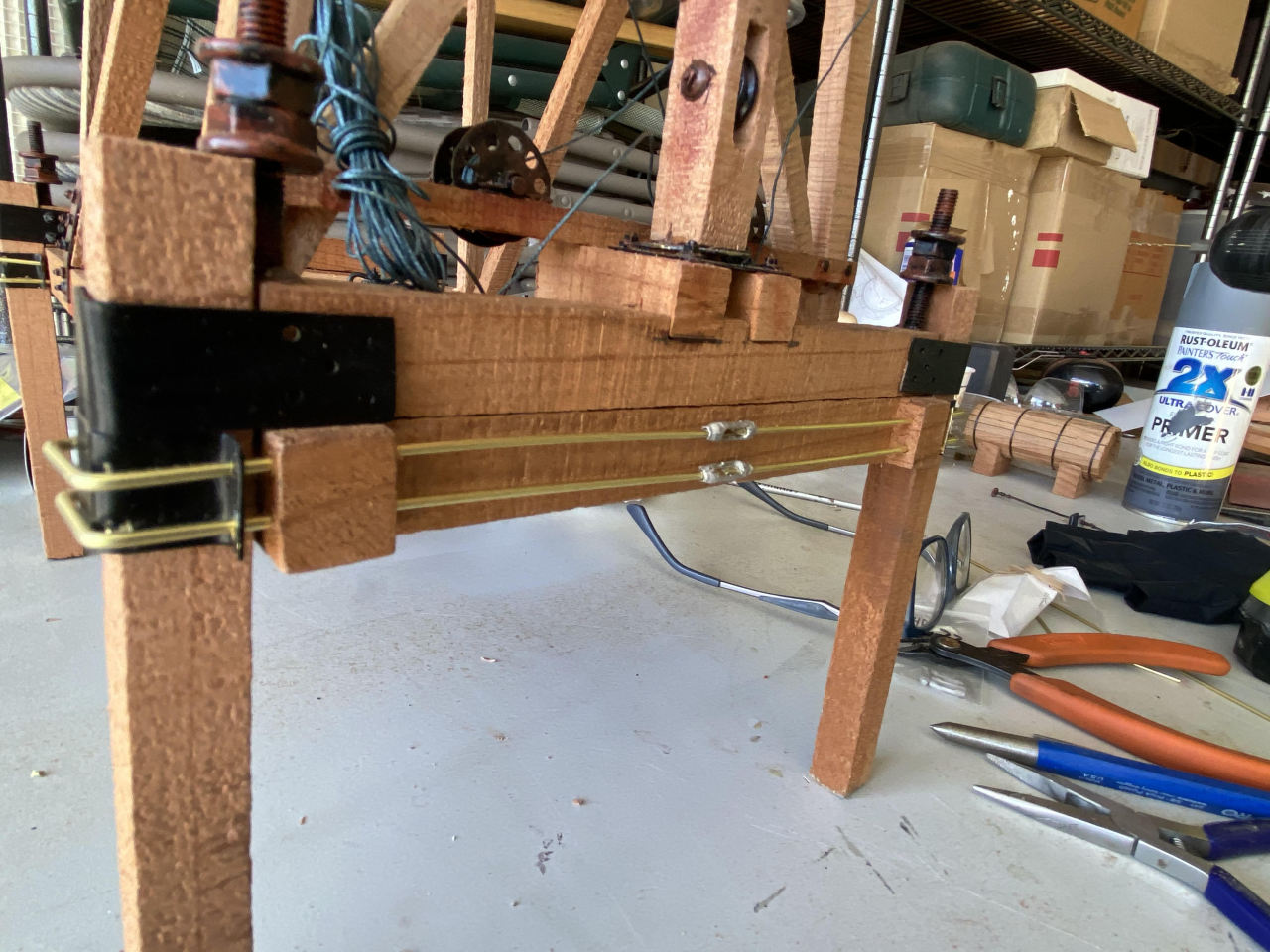
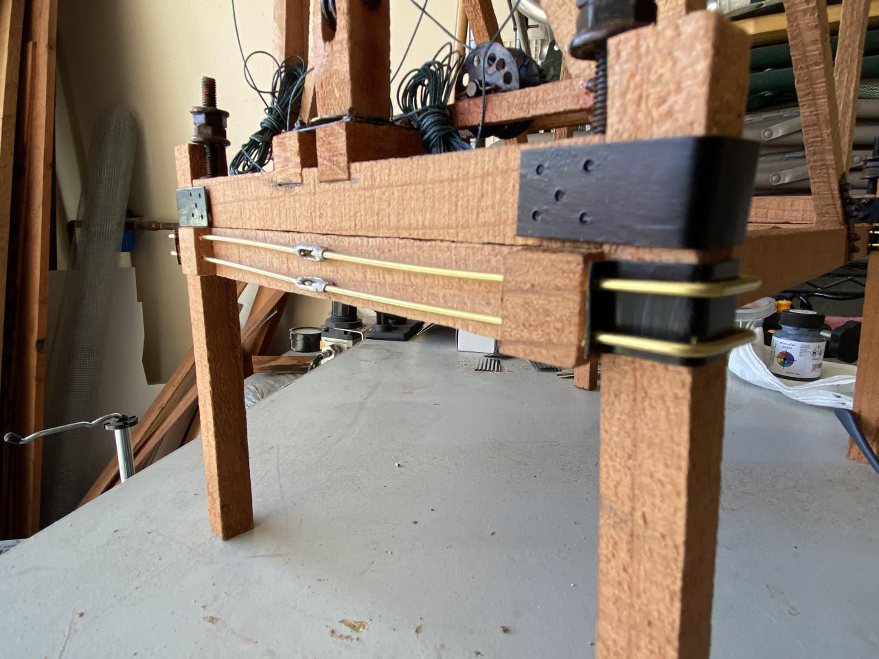
I’m thinking this thing might get finished one of these days. I’ve also talked a neighbor into helping me sew the tent cabins for the loggers. Sweet!
Ok, Jim, I had assumed all this time that the strappings would utilize typical u-bolts, but I see you have connected the sides together with turnbuckles. Is this prototypical? If so, I learned something and it does make sense. Just curious, doesn’t matter to me whether they are prototypical or not, just for my own info.
Dan: I am not sure whether it is prototypical. I’m copying somebody else’s model (Frank Palmer of Sundance Central RR) [link] and his looks like this:

In some sense they are u bolts that are veeeeerrrrrrry loooooooong…
It makes sense, Jim, by transferring the horizontal forces to the outer surface of the legs vs pulling on that short end of the side beam, keeps everything in compression. It also eliminates any rotational forces from being induced into the side beam which would have the effect of tearing the whole platform apart.
I’d want steel plates on top of the legs where the height adjustment bolt rests … that part looks a tad funky … less authentic and more like a get 'er done compromise, IMHO.
I went back and looked at some of the prototype photos that our resident history enthusiasts posted on this thread, zoomed waaaaay in and did a little bit of photo enhancement to see these 2 photos…
The first is the overall front of the loader showing the turnbuckle detail on the friction clamp holding the loader onto the pilings:
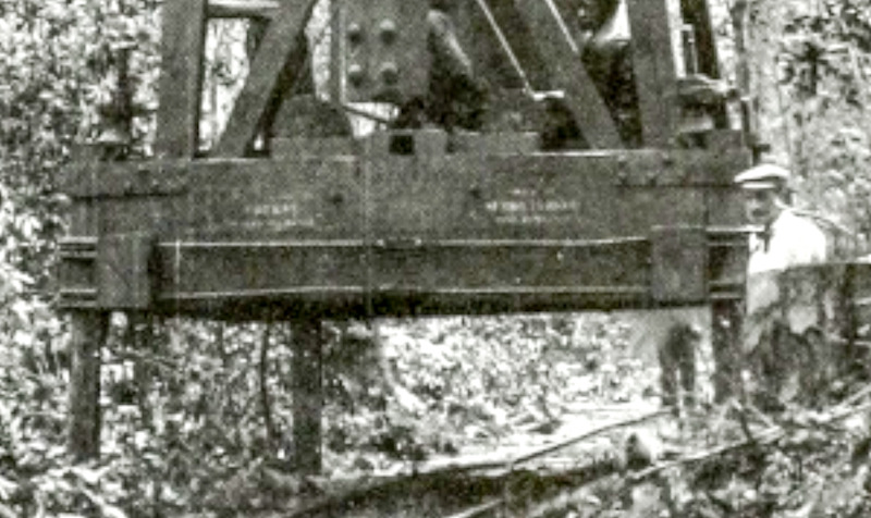
And the second is zooming in to one of the leveling bolts. It appears to me to just be resting on the bare wood of the piling (just to the left and above the guy’s stylish hat):
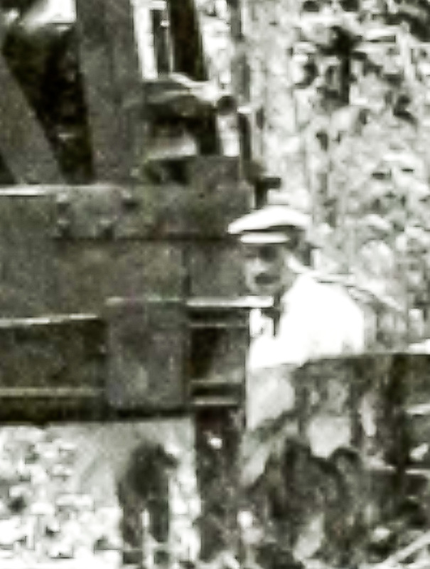
John, here’s my theory, please correct me if you have a different one:
- when they went to set up the loader they drove the pilings in right there in the field, perhaps using wood they cut there,
- then they lowered the loader on, threading the pilings through the top guide and used the bolts to level it temporarily,
- they then tightened the turnbuckles to cinch the lower friction straps to provide the primary method of holding the loader on the pilings
- at this point the bolts are not providing the primary support, alleviating the need for a metal cap on the piling
wdyt?
I do not think they drove any pilings. The adjustments are for the un-level ground after it’s set in place. I’m hesitant to guess as soon as I do Rick will chime in …(https://www.largescalecentral.com/externals/tinymce/plugins/emoticons/img/smiley-embarassed.gif)
Looks mighty flat to me, I think putting that much weight on end grain would deform it some what. Specially on the edge.