Greg Elmassian said:
The gauge (I have 2 of them) is remarkably close to NMRA specs, and I also endorse the use of it.

Well shit if you are endorsing it then I’m in 3 fold!
Greg Elmassian said:
The gauge (I have 2 of them) is remarkably close to NMRA specs, and I also endorse the use of it.
Well shit if you are endorsing it then I’m in 3 fold!
Greg good call on the calipers. I have an excellent set of calipers. Not digital but I can do the math. I am embarrassed I didn’t think of that.
OK now for the abrupt hinged rail. The number one reason is for the very easy sliding. When I attempt to piir the sway bar flop actuator on it I want it to move with as little effort as possible. The second reason. Is to keep the whole switch as short as I can.
My thinking was that in order to “bend the iron” even with aluminum they would need to be long to get the leverage. I messed with flexing this stuff and I just think it will require to much effort to move them with the flop actuator. Another sacrifice.
Double posr
Ahh… the flop actuator, forgot that on the stub switch.
Have you decided on the mechanism to flop it?
Greg
Well I have decided on what to try first let’s just say that. I know I am in uncharted waters now. The sway bar idea I think will be the strongest most positive one.
I will sketch my idea on a napkin
Devon Sinsley said:
I will sketch my idea on a napkin
Quick learner he is!
Devon Sinsley said:
John mentioned the need to establish my back to back standard for my gaurd rails. That is the next step is getting the guard rails in place. I will be looking at the nmra and g1 specs as guidelines. But with the issue of such radical geometry would I want tighter or looser tolerances to help negotiate the frog such a nasty turnout. It actually is running pretty smooth at this point
I didn’t see this point mentioned, so let me add - the biggest problem that folk run into when making switches is that their rolling stock has wheels from different vendors with different back-to-back measurements.
Devon - I’m glad to hear your truck has G1MRA standard b-to-b, but if you introduce an LGB wheel it will require that you open the check rail gap across from the frog or the wheels will just ride up over it. Then your G1MRAwheels will hit the frog and derail. You have to pick a standard and more-or-less stick to it.
Pete,
John made mention on setting the back to back on another thread and I brought it back here. Essentially he said the same thing as you. I have pretty much decided to stay with the G1MRA standards. The nice thing is what I have built matches them pretty close. And since the switch I am laying now is just a design phase and will get set on ties when I am satisfied with the design I can make sure they match the specs as will any future ones.
What you guys are seeing being built is just a prototype and a learning experience. It will serve as the template for those that follow. As for wheel sets I will be using probably only one wheel set through out. Not sure yet what but I do know it will be a set that has wheel bearings to help negotiate the curves. So standardizing them will be a must as well.
Heres the napkin of what I hope to achieve

The loco entering from the top with engage a long flat brass bar that is on a hinge. As it engages it it will fold it into the web of the rail with its wheel flange. As the bar is pushed into the web it with push a rod that is attached perpendicular to it through a hole in the web of the rail that is attached to the sway bar. This will cause the sway bar to be pushed outward. On the other end of the sway bar with be a rod that attaches to the stub rail. As the sway bar is pushed out it will pull the stub rail with it and into alignment. A regular flop spring will be used to maintain that position when the locomotive and train exits. On the return trip if course this direction will be already established. Another identical set up will be on the inside of the opposite outer rail and will flop it to the other side. and there you have it a flop stub switch. That’s the plan anyway.
I have been giving it some thought and I think I only want one of the two reversing loops to be a true flop. The other I think I will want to be an automatically left selected switch that when the train runs through it will always spring back to the left position. The reason for this is I might decide to throw a spur into the industrial area and the trains will need to always come in so they can back down the spur.

So to accomplish this I will only make a actuator on the right (straight) side. And then use a spring on the ties like in regular automatic switches or I could put a spring in the actuator rod between the web and the actuator hinged bar that will, after the train passes, push the actuator back out and force the rails to the left.
Devon,
sometimes i get the feeling, that you over complicate things.
look at he pic below. there you got a “fifteen minute half stub switch”, made from a LGB crossing and a piece of curved track.
with a 6 or 12" long, movable straight, the stubswitch build is history.
and if you don’t like the wye type, make one leg straight and the other curved more.
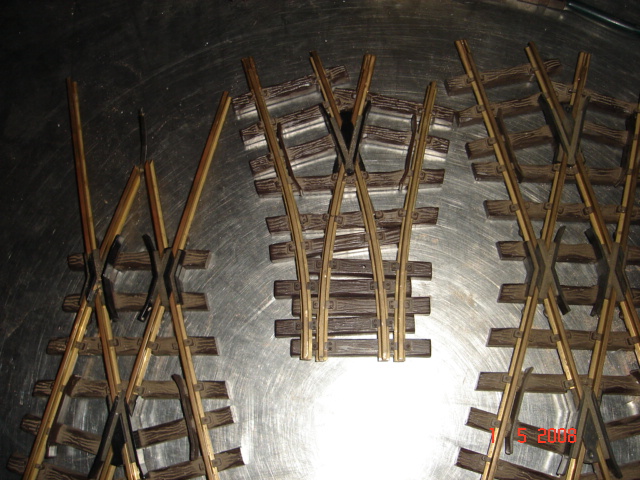
How is that simplifying matters exactly? Not sure making one is any harder than modifying a cross over. It also does not eliminate some other issues such as LGB is code 332 and I am laying 215. Not to mention I would have to be buying 4 cross overs (1 looks like it would make two switches) at $50.00 each ebay prices (at least with the current design) plus sections of curved track in order to make seven stub switches. And then the LGB curved track is R1 curves and I am going 30" so I would have to bend the rails anyway. Also the whole project is going to be laid on real log ties like these

I don’t think making my own stub switch is over complicating anything. Its actually pretty easy. Considering I now have a working stub switch that meets my exact requirements made out of $3.50 worth of rail. It might have taken me a little to figure it out but in reality it wasn’t hard and the next ones will go like clockwork now that I have a template. The hardest part was brazing the frog point and now that I know what I am doing that won’t be hard.
Besides I never looked for the easiest route. I do thank you as always for the suggestion. It is a good idea.
Well the flop actuator as I have it envisioned won’t work I don’t think. It has a mechanical range of motion of 1:1. The actuator hinged bar is mounted between the outer and inner rails. The maximum range of travel at best is 3.5 mm with is the distance between the webs and this would also be less the thickness of the bar. The rail needs to slide 5.5mm give or take. I have to develop a mechanical advantage of about 2:1. That would mean that the stub side of the sway bar needs to move twice as far as the fix rail side.
This project is so intriguing but I am starting to wonder if I really want to take on this challenge. I love good challenges but at the end of the day I am not sure this is worth it. Not when I can make two regular switches using a time proven simple flop mechanism. So unless someone has a quick fix idea then I may bag this idea and sjut use regular flop switches in these two spots.
yep. code 215 and the rustic ties are good arguments against my idea.
on your money point… it is the other way round. a crossing has four frogs. a stub switch just one.
(btw: LGB R1 is 30° per section)
Korm Kormsen said:
yep. code 215 and the rustic ties are good arguments against my idea.
on your money point… it is the other way round. a crossing has four frogs. a stub switch just one.
(btw: LGB R1 is 30° per section)
Yes but in your picture you are only using the inner frogs. The outer two frogs don’t look like they would have the right geometry for making switches. I could be wrong on that point though that’s a quick observation. I also realize that the LGB R1 curved section is 30 degrees but it still is a 48" (ish) diameter curve not a 30" diameter curve. A foot and a half in diameter is a big difference when ever inch counts.
I agree the whole concept is not “easy” or “conventional”. But then again I never expected nor claimed that it would be. In fact I am doing it because it defies convention and bends the rules to do something uniquely different. Easy would have been to do an HO layout in the space I have.
I do like the idea though. And if someone were to decide to do a similar project with 332 track and wider more standard R1 curves then that would be a very solid plan for stub switches. It just isn’t for me and the “feel” of this project.
Devon Sinsley said:
I agree the whole concept is not “conventional”. But then again I never expected nor claimed that it would be. In fact I am doing it because it defies convention and bends the rules to do something uniquely different.
A man after my own heart. (http://largescalecentral.com/externals/tinymce/plugins/emoticons/img/smiley-wink.gif)
sorry, the first time i read your (") inches for (°) degrees. hence my missunderstanding.
Korm Kormsen said:
sorry, the first time i read your (") inches for (°) degrees. hence my missunderstanding.
Korm,
I know your trying to help. I honestly do appreciate yours as well as anyone’s input. I have learned a ton from you guys. If it weren’t for the help and info here I wouldn’t even try this. So please don’t think because I am not accepting of your idea that I am not sincerely grateful for it. The emotionless internet can sometimes make it seem as if someone is being rude when that is not their intention; and I have a way about me that seems to beg for this conclusion. Its not true though and I hope you do believe that I am not dismissing your suggestions I just am not going to use them. Keep on offering them, I respect all that you have to say, your very helpful.
Devon Sinsley said:
How is that simplifying matters exactly? Not sure making one is any harder than modifying a cross over. It also does not eliminate some other issues such as LGB is code 332 and I am laying 215. Not to mention I would have to be buying 4 cross overs (1 looks like it would make two switches) at $50.00 each ebay prices (at least with the current design) plus sections of curved track in order to make seven stub switches. And then the LGB curved track is R1 curves and I am going 30" so I would have to bend the rails anyway. Also the whole project is going to be laid on real log ties like these
I don’t think making my own stub switch is over complicating anything. Its actually pretty easy. Considering I now have a working stub switch that meets my exact requirements made out of $3.50 worth of rail. It might have taken me a little to figure it out but in reality it wasn’t hard and the next ones will go like clockwork now that I have a template. The hardest part was brazing the frog point and now that I know what I am doing that won’t be hard.
Besides I never looked for the easiest route. I do thank you as always for the suggestion. It is a good idea.
I love your ties. With weathered rail that will make great track.
Devon Sinsley said:
Heres the napkin of what I hope to achieve
The loco entering from the top with engage a long flat brass bar that is on a hinge. As it engages it it will fold it into the web of the rail with its wheel flange. As the bar is pushed into the web it with push a rod that is attached perpendicular to it through a hole in the web of the rail that is attached to the sway bar. This will cause the sway bar to be pushed outward. On the other end of the sway bar with be a rod that attaches to the stub rail. As the sway bar is pushed out it will pull the stub rail with it and into alignment. A regular flop spring will be used to maintain that position when the locomotive and train exits. On the return trip if course this direction will be already established. Another identical set up will be on the inside of the opposite outer rail and will flop it to the other side. and there you have it a flop stub switch. That’s the plan anyway.
I have been giving it some thought and I think I only want one of the two reversing loops to be a true flop. The other I think I will want to be an automatically left selected switch that when the train runs through it will always spring back to the left position. The reason for this is I might decide to throw a spur into the industrial area and the trains will need to always come in so they can back down the spur.
So to accomplish this I will only make a actuator on the right (straight) side. And then use a spring on the ties like in regular automatic switches or I could put a spring in the actuator rod between the web and the actuator hinged bar that will, after the train passes, push the actuator back out and force the rails to the left.
WoW… . whut an eye-D-r . . . 
So I think I have a major redesign to do. Shawn entertained in the other switch building thread an interesting idea of making stub switches fit where and existing Aristo wide radius switch exists now so that he wouldn’t have to redo track. This got me thinking about how, with my very limited experience with this switch, one would accomplish that. To my thinking and current design stub switches seem to need to be longer. But then I looked at my switch geometry and that of the real thing. My switch is either too long or can have longer stub rails for its given length.
Right now it is built in such a way as the two diverging lines stop at a point where the rails are parallel to one another with the foot of each rail touching one another; then the stub rail begins. In order to get the best alignment between the stub rail and the fixed rails I split the difference and lined the stub rail in between the two.
Now looking at it from a fresh perspective I think the better way is to cut the fixed rails closer to the frog where they are now no longer parallel but well into diverging. Then I can either move my stub rail closer or use longer stub rails and line them up so that when they are straight they are inline with the straight diverging line. And then when they swing over they actually will line up better with the curved diverging rail. I think this actually will improve rail alignment and have the effect of a shorter switch or a less abrupt switch. Both options would have their advantages and disadvantages. I have to weigh overall length with to the abruptness of the alignment. The shorter the better but smoothing out this switch maybe the better option. 12" is a pretty dang short switch so I think I would lean toward longer stub rails and keep the length. I have enough left over rail I think to play with this.
Edited: looking at it some more the wider separation will eliminate the problem I have with wanting to “pick” the fixed rails. I had a bit of a problem with this and had to fix it by not aligning the stub rails perfectly. I actually let them slide over further than they should. While this fixed the picking problem it looks wonky. by separating the fixed rails this wont be an issue.