Sean McGillicuddy said:
Todd
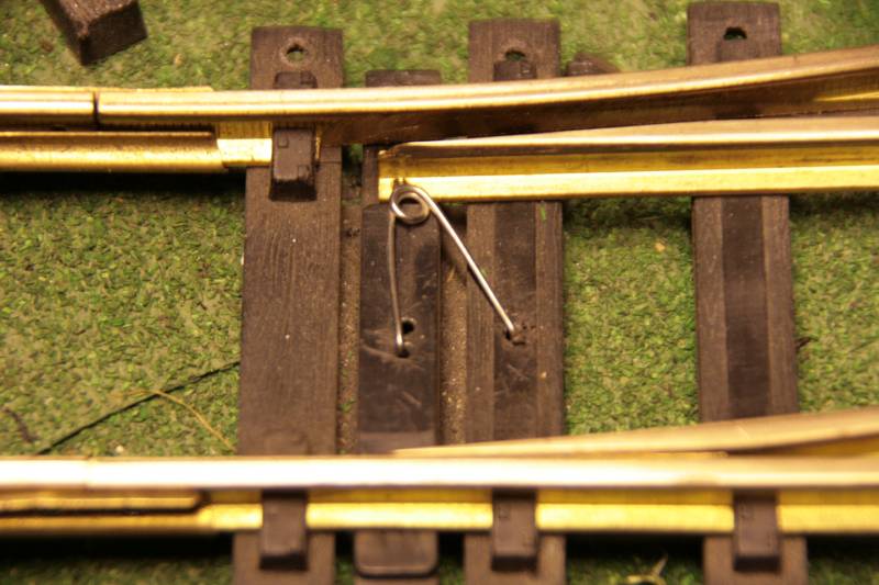
Is this something like what you were trying to describe?
Following this interesting thread. I love stub stub switches, . . . they look KOOL and old fashioned.
This photo … how does it work ?
Kevin,
I use this spring method on my RR and our club RR too. Any train traveling with the points flips the points over for the direction of travel the train is going. They do not reset. Simple and works every time. The only caveat is the train going over it must be heavy enough to overcome the spring. I do have a problem with the pilot trucks on my fleet of 4 B’mann 10 wheelers. They all seen to derail if I do not manually set the points!
I understand the above photo. That is the standard flop switch. And in case anyone is confused this, as is, will not work on stub switches because the rails that make up the two tracks in the switch are fixed unlike above where the point rails move back and forth within the switch. Stub switch have the moving bits outside the switch.
What Todd I think is doing is adapting this idea by making the two stub rails (just so we are all on the same page I am calling the stub rails the moving rails leading into the switch, is that right?) move with a spring and brass strip that extends into the switch that will engage the loco. As the locomotive engages it, it will in essence push/pinch the brass strip against the outside rail and thus push the stub rail over with it. as the loco leaves a clip spring like above will return it.
I think I get it. As I described it this switch always works one way; train exits the switch always to one side and enters the other. I can’t picture the true flop version.
Todd. . .
Devon Sinsley said:
I understand the above photo. That is the standard flop switch. And in case anyone is confused this, as is, will not work on stub switches because the rails that make up the two tracks in the switch are fixed unlike above where the point rails move back and forth within the switch. Stub switch have the moving bits outside the switch.
What Todd I think is doing is adapting this idea by making the two stub rails (just so we are all on the same page I am calling the stub rails the moving rails leading into the switch, is that right?) move with a spring and brass strip that extends into the switch that will engage the loco. As the locomotive engages it, it will in essence push/pinch the brass strip against the outside rail and thus push the stub rail over with it. as the loco leaves a clip spring like above will return it.
I think I get it. As I described it this switch always works one way; train exits the switch always to one side and enters the other. I can’t picture the true flop version.
Todd. . .
Sounds like you’ve got it.
Devon, a true flop version just depends on how you place the over center spring. It can be placed to hold just one position, or hold either position.
OK, let’s try this. Pretend this is the stub switch and the four rails to the right represent the four rails. The black triangles represent “roll overs” that contact the flange and the wire/pin goes through the rail webs. Longer tubes may be needed to keep the wire moving in the right direction (rather than bending) over its travel.
This shows two ways (top and bottom). A third would be to use the top “actuator” but instead of pushing out, rotates about the long shaft (ala sway bar on a car). Then you can gain mechanical advantage/distance by altering the lenght of the two arms. The lower method also has a mechanical/distance advantage.
These could also be done if the rail pivots if there were eyelets or tubes to guide the wires.

David Maynard said:
Devon, a true flop version just depends on how you place the over center spring. It can be placed to hold just one position, or hold either position.
I realize that on the regular style switch. I am not sure a true flop stub can be made. I dont need it to be a flop though it would be nice, that would be secondary. It just needs to be automatic even if the trains have to only travel one way all the time.
Ok Todd,
Thanks for the cave drawing. I think I am following at least the first two options. You’re (I did it right Joe) still over my head with the third sway bar one. If I am seeing this correctly by placing actuators on both outside rails and correctly positioning the center clip spring it would be a true flop switch with bi-directional use. You mentioned this but it took seeing it to understand it. I think the top one would be easier to make but the bottom one would have the better advantage and be more reliable.
I will certainly be playing with these ideas.
On the normal flop switch as David mentioned the spring placement makes it uni-directional or bi-directional. Which hole arraignment/alignment makes it a true flop. I assume like Todd has drawn I would do it the same way for the flop stub only reversed like he show.
I can also see right off that the distance between inner and outer rails will make a difference here. Other wise the switch actuator might have the opposite effect in pushing the locomotive over instead of the rail. Of course the flop spring will assist in switching I would think if it is a true flop. A uni-directional set up would work against switching and want to push the loco over. So the rails will have to be close like the flangeway so that as it hits the actuator the wheel back will ride on the other rail like a guard rail and that will then for the actuator to move the rail.
This will help you with the sway bar image (literally).
Consider that the brackets/bushings are mounted to the ties and the arms face up. The linkage connects the “rollover” to the stub end. The difference in the length of the arms provides mechanical/distance advantage.

As for the “roll over.” It is simply a piece of springy brass/copper strip bent into an arc with a pin/wire/tube (PWT) mounted at the underside center of the arc.
This PWT sticks through a hole in the web and a collar/larger diameter tube goes over it to “pin” the piece in place so that it can “float” in and out when flexxed but can’t get away from its position. This is necessary to let the ends slide along the web as the piece flattens. It may be necessary to “undercut” the rail head to get good wheel engagement.
While this “floating” assembly shouldn’t derail the train, as was pointed out, the presence of the other rail pins the wheel in place to help avoid this possibility.
OK I admit to being a bit slow. That did not help at all. Lol sorry Todd I know you’re trying hard to help but this one is just not sinking in for me. The first two yes totally. But this one not even a hint of a clue about what your talking about
Turn the two red brackets/bushings 180 degrees and fasten them to the ties.
Turn the blue bar 90 degrees such that the 90 degree bent arms face upwards.
Connect one red endlink to the roll over mechanism described above (rather than the bottom of the shock absorber). You’re not using the round disk on the end, just the rod.
Connect the other red endlink to the stub rail. Again, just the rod or whatever is necessary
When you push one endlink, the bar rotates pulling the other with it. If the two endlinks are at different distances from the center of rotation of the blue bar, you realize a mechanical/distance advantage.
Form one of my favorite movies “awh lights shines on marble head!” I get what your doing now. A major part that I as missing is this is being used in conjunction with one of the first two actuators and that is what your calling a roll over right? So as you push on one of the two mentioned actuators the rod on the actuator is attached to the sway bar(instead of the stub rail) which then is attached to the stub rail. Am I getting if
Progress. I reworked the frog area. I was able to, with practice, braze the aluminum frog point together. Its definitely more like brazing than soldering. and I don’t think its a super strong joint but for what I am doing it holds it together well and fills the gaps.


The flange ways at the frog and where the rails will meet the stub rails are 2.5mm. The gaps between rail heads at the frogs is 7mm. Way better the wheels does not drop into the frog and it is pretty dang smooth. I single truck tracks through nice. can be a few hitches if I get the truck at an unnatural angle. I put a Bachmann Lil Big Hauler tender on it and it tracks with no issue. Over all in operation I think this will work fine. The diverging curved wing rail needed to be bent further away from the rail so it is not parallel with it. It is just to sharp of a curve and causes a bind as well as in returning to the switch it wanted to ride up on the wing rail. I want to put in guard rails which I think will prevent the unnatural twist I was talking about and give added insurance that it tracks through well.
A 30" diameter curve is not friendly in a turnout that’s for sure. I can see why the toy switches have the compromises they do. But I am determined to make the tweeks to make it as close to prototypical as I can. This is 100% tread bearing with plenty of flange clearance on the Bmann wheels.
Next up will be the guard rails. The I will tackle the stub rail side of the picture. Now that I have it laid out the torsion bar method for automatically flopping it makes sense to me. I have some ideas on that. That will be the fun part of this project (well its all fun). I think it will work just fine.
Devon Sinsley said:
Next up will be the guard rails. The I will tackle the stub rail side of the picture. Now that I have it laid out the torsion bar method for automatically flopping it makes sense to me. I have some ideas on that. That will be the fun part of this project (well its all fun). I think it will work just fine.
If you do it like the sway bar, you could put a “handle” on the verticle piece at the stub rail and pose a guy like he is “bending the iron.” If you had an articulated figure that could move with the assembly, it would be very (http://largescalecentral.com/externals/tinymce/plugins/emoticons/img/smiley-cool.gif).
Actually, I guess you could find a way to put a handle/figure on it regardless of how you do it.
Ok slow down articulated people??? (http://largescalecentral.com/externals/tinymce/plugins/emoticons/img/smiley-surprised.gif)that would be cool though
Get a “Gustav” from an LGB hand car and the arms can move.
I actually have him stand on on a USA reefer and push ice into the hatch. It was featured in Garen Railways Magazine and you can see him at 3:50.
Gustav could work
just be sure to save and resell the red box Devon!!!. Boy you think you are having trouble understanding what they are saying, I am reading a bunch of words that might as well be Russian, and after reading 2 times , still not sure what I read.