Waiting and watching 
OK well I am not very far along but the audience is getting restless

This is the beginnings. So its code 215 llagas aluminum rail. Nailed straight to my work bench, not sure how good of an idea that was but the whole top of the bench is going to get covered in formica so oh well. At this point The top perpendicular pencil line is where the top of the switch will end. At the bottom edge is where the moving “stub” rails will be. They will be 4" long. Overall length of the switch will be 12 1/2" It has a 30" diameter through the curve. One hitch is that it isn’t the smoothest through the “frog” are (is it still call a frog when it is built this way?)This is due to the curve through that area instead of being straight going in and out. It works it just has a bump going through it. I do see now why it really should be straight through the frog. Since this is a radical small curved layout some sacrifices need to be made to keep things tight. I hope to smooth it with guard rails. Playing with it I think this will help keep wheels from bumping where the “frog” is. If not I may decide that it really should be straight through this section even if only for the length of one truck. We will see. Where the two rails join at the top of the “frog” I will try brazing them together with some aluminum brazing rod. We will see how that goes as well. The next step is to cut the rails and pull the whole mess off my bench and make a permanent base and then cut my hand hewn ties. Then nail the swithc down.
Kinda fun really since I basically have little more than a clue about what I am doing. This is how I learn. People can tell me all they want but until I start playing with stuff it does it make sense. One thing about me is I will fuss with it until it works. Since I can’t really build the actual layout yet I will be developing this turnout and perfecting it and then stock pile what I will need.
your wind rail flangeways look a bit wide, what did you build them to?
In fact where are you getting your specs for flangeways, etc.?
Greg
OK Greg,
That is actually a very good question because I am wondering about this. I am using the NMRA standard specs for Large Scale in metric. The flangeway on those specs call for 2.92mm +.05mm and -.58mm. Due to the spikes I am at about 3.5mm to 4mm which I knew I was too wide. So what is the solution? How do you get them closer? Now here is another problem question. First I know I am already asking for trouble by not having a straight section through the “Frog”. Before I spiked the stuff down the way it is I did have them closer but on the curved section with that tight of a curve it just binds stuff up. This is one of the reasons I can see for going through and especially out of the frog straight. That became evident to me. So here is the very rookie question. What is the purpose of the little wing rails? As I move a truck through the frog it just seems like it is in the way and not really doing anything at all. A guard rail on the inside the outer rails makes more sense to me as that will prevent the wheel from bouncing on the frog gap as tit will keep it from touching there and instead limit the movement on the opposite wheel back.
Now I know your a big proponent for not curving through the frog and that is pretty evident why after playing with it. This whole project though is inspired by Vics breaking the rules (http://largescalecentral.com/externals/tinymce/plugins/emoticons/img/smiley-laughing.gif). So what are practical solution for making a smooth tight turn out? I can see a distinct problem with the curve through the frog and I assume this maybe one of the chief complaints of the “toy” switches. So If I straighten it out which I am thinking needs to happen, especially since I am already binding things with such a tight curve, Whats the shortest practical distance that it can be straight. By looking at it, if I did it for even the length of a truck wheel base it would vastly improve things by allowing the whole truck to get through the frog without the curve forcing it to touch and I then could have narrower flangeways. Another observation is again those outer gourd rails seem like they could be the limiting factor for keeping the wheels away from the frog gap. In doing that then the flangeways at the frog could, it seems be very wide to prevent binding, because the other guard rails will determine the tracking through the frog.
Again I know I am not playing by the rules but I am curious on thoughts as to accomplish what I want smoothly and reliably even though it wont be prototypical.
OK I answered one of my own questions. I see why the flangway gap being wide is an issue. It lets the wheel drop in. So I am convinced at this point that I do need to straighten it out through the frog at least some and tighten those flangeway gaps up. That brings me back to my question of what is the shortest distance it needs to be straight entering and exiting the frog. Seems to me the critical is straight leaving the frog more so than into the frog. Can I leave it curved right to where the wing (wind?) rail portion bends away? and then straighten the diverging rails for say the distance of a truck and then get right back after my tight curve. This wouldn’t effect the overall curve much.
So the wing rails do two things… away from the point of frog, they control the wheels position on the rail… proper wheel geometry and back to back spacing does this.
Near the point of frog, the wing rail helps support the tread of the wheel so it does not drop into the frog.
If you can find some good illustrations, the wing rail will support the wheel until the point of frog can support it.
Too much flangeway gap and the frog area is all messed up and the wheel drops into the frog with a great bump.
In model trains, many compromises were made, and the upshot is most flangeways are too wide and wheel geometry is bad and stuff does not work well.
LGB solved this by using deep flanges, and flangeway DEPTH such that the wheels actually are supported by the flange riding in the bottom of the flange… this is known as “flange bearing frogs” and can work well, IF all wheels have the same flange depth… and usually those flanges have to be ridiculously “deep”…
There are better ways to do this, but it works if you follow the rules, unfortunately it’s unsightly and won’t work with more reasonable appearing flanges, not to mention not even close with semi-scale flanges.
So the solution is to cast or solder the frogs so you can get the flangeways right, and then your point of frog will go “into” the frog “deeper” and then you have a better chance of continuously supporting the wheel through the frog and no bump…
Interestingly it’s easier to accomplish with switches with a lower frog number, like you are building… it’s way more difficult with #6 and up frogs.
So, work on the frog a bit more, and get it tuned up… also look at the G1MRA specs, some of the NMRA specs are way too sloppy… too much “grandfathering” of the toy trains tolerances from the major manufacturers… (i.e. do not copy LGB or Aristo or USAT switches)
Hope that helps… (and you can look on the track and switches pages on my site… more info there)
Greg
One thing I noticed in the picture Devon is that on the curved route, your divergent rail isn’t inline with the frog. Its offset a bit to the left. That will cause major issues. The divergent rails need to be inline with the frog point so the wheels can roll smoothly from the rail to the frog.
I built a switch that was curved through the frog. It can be done, but the wing rails need to be opened up a bit to reduce binding.
As for reducing the flange-way between the wing rails and the frog point, I didn’t spike inside there. That way the foots of the rails could touch each other, and with code 332 stainless, that gave me a proper flange-way spacing. On the prototype, those two parts are often bolted together through the web with spacer blocks between the webs, and spiked on the outside of that assembly.
The spacing I used for my flange-ways was 1/8 inch wide and 1/8 inch deep, and that seamed to work well for the switch I built. You just need to make sure that when you put the guard rails in, the gauge is proper, so the guard rail will hold the wheel flange, preventing the wheel flange on the other wheel from hitting the frog point.
Greg and David,
Both of you guys make perfect sense; and I can visualize what your saying and I think I can apply it with what I have. First off I can see where eliminating the spikes in the flangeway will allow me to move them closer and I have already seen the benefit of doing that. much of the bounce I was experiencing was indeed the wheel dropping in which at first I failed to notice but last night realized. So no matter what, I see why the gaps need to be closer. I have yet to experiment with soldering/brazing the aluminum so that will be the next challenge to see if I can solder the frog part of this together. If not I am sure I can come up with some way of attaching it all together at the frog so I don’t need spikes in the flangeway. If all else fails I will get some brass track from Llagas and make frogs from that, i have confidence in my ability to solder brass. If all else fails I can make my own one piece frogs and cast them. I have options to play with there. That seems to be the primary battle front right now.
David you mentioned the divergent curved rail not being lined up to the frog and you are spot on. It is slightly left and I have to say you have a good eye, I hadn’t noticed but this was a “solution” to a problem that I had already realized was no solution at all. I moved it (not realizing it was not lined up) to keep the wheels from striking the frog point and derailing it. This is what really got me looking at the guard rails which I knew I needed to install but hadn’t yet gotten around to yet. I realize now that the guard rails properly spaced will prevent the wheels from striking the frog point.
Now back to the pesky wing rails. I get exactly what your saying Greg that at the frog point that bit of rail is needed to support the tread across the frog gap until the wheel can ride onto the frog point. So I see that. But what about after the wheel is now on the frog point. Can that wing rail be opened up like David suggests so it will prevent binding since we are still dealing with a curved exit from the frog?
All of this is why it is nailed to my bench (although I think I am going to cut all the rails and move them to a more sacrificial piece of wood). This is all one big experiment and learning experience. I actually quite enjoy this sort of thing because until I make something I really don’t understand it. I am no where near the point of saying I have a successful working turnout. But I appreciate the help and practical advice.
Yes, after the wing rail has done it’s job of helping transfer the wheel to/from the point, it could be opened up, but there is no reason to do that, just keep the constant flangeway width. Sure if you are curving the point rails after the point, now your wing rail would be curved.
All in all, bad idea, for the short distance the points and the wind rails “overlap” I’d keep it straight, curve it away from there… you have enough issues ha ha!
Another thing you can do is drll small holes in the foot of the rail and run a spike through there, although if you are using code 215 an ordinary spike head might sit too high.
Greg
Devon, another option instead of soldering aluminum rails would be to put some JB Quick in the gap between the point and the wing rails. Just make sure you keep the flange-way open down to about 1/8th an inch
The wing rails also serve to keep the wheels from hitting the other diverging rail when the wheel is approaching from the wide side of the frog. That is why the wing rail and diverging rails are either one piece, like yours, or are bolted together. So past the point, they can be opened up a bit. Greg has a valid point. My switch was curved, but it was about a 9 foot radius curve. I didn’t experience binding in mine, but yours is much tighter. Going straight for the length of the frog (an inch or an inch and a half) would probably be the best idea.

Well I think then with all the above advice is to do a couple things. 1) unnail from my work bench (that really wasn’t so well thought out (http://largescalecentral.com/externals/tinymce/plugins/emoticons/img/smiley-tongue-out.gif)) 2) Then figure out how to connect the frog portions together. I do have some aluminum brazing rod and I will give that a go. I don’t see why that wont work but I have heard aluminum doesn’t always play nice. 3) I am going to straighten the exit of the diverging track at least an inch (this is the length of the wing rail) maybe even two. As Greg says I have enough other issues going on that and this one will only make a very minor, likely not even noticeable, overall “widening” of the radius.
I have nothing but time to get this to be a very acceptable turnout.
![]()
Sean what pictures do you want? Geez, I did post a picture of where I am so far. I am not very far. There isn’t much to show yet. (http://largescalecentral.com/externals/tinymce/plugins/emoticons/img/smiley-wink.gif)
Also this tread was started as a theoretical question on how to do something. I never really meant to start a build thread on the subject but I am glad to do so that way people can help walk me through it like Greg and David are doing. It will be a slow process and I am afraid wont be the most exiting of threads. But I will bring people along with me as I learn. I will keep posting with pictures as it develops.
Devon Sinsley said: Sean what pictures do you want? Geez, I did post a picture of where I am so far. I am not very far. There isn’t much to show yet. (http://largescalecentral.com/externals/tinymce/plugins/emoticons/img/smiley-wink.gif)
Just trying to beat Rooster to the question … Is it done yet? It does look like your learning a lot on this … Keep up the good work Devon!(http://largescalecentral.com/externals/tinymce/plugins/emoticons/img/smiley-laughing.gif)
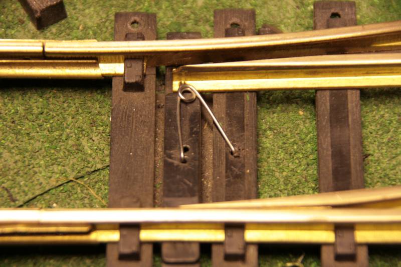
Another way to do the “flop,” maybe easier/better.
Again, a piece of brass strip mounted along the inner edge of the outter return rail. Drill a hole through the web. Bend a piece of piano/brass wire to form a “U.” Solder/attach one end of the U to the stub rail and let the other end protrude through the hole in the web.
So when the train comes along and pushes in the brass strip, the strip pushes the wire sticking through the hole pushing it outward and taking the stub rail with it. In this case, the brass strip could be bent to a V shape (wire contact at center of V with tips of V toward the rail so the wheel doesn’t catch on it) so the train could approach from either side if someone threw the stub into the other direction. In fact, you could do it on the outter rail on both sides and the use a hairclip spring and the train would alternate directions each time it came through. (http://largescalecentral.com/externals/tinymce/plugins/emoticons/img/smiley-cool.gif)
Could also be done wth a pivot rail with an eyelet to position the wire along the pivot rail.
Could also be done like an anti-sway bar on a car where the long bar sits at ground level within a tube and the two short bars pivot about the long bar and engage the rail with a pull rod.
Devon,
Use JB Weld to hold the pieces of rail together. And get rid of the spikes on the inside point of the frog. That way you can get the frog points much closer to the wing rails. The wheel set shouldn’t need guard rails on the sides to hold the wheels across the frog if you build the frog and wing rails tight. My #9 frog on top with JB Weld, and the bottom is the Llagas #4. What I would do first is file the base rails of the frog point down so that you can slip it in closer to the wing rails.

Todd Brody said:
Another way to do the “flop,” maybe easier/better.
Again, a piece of brass strip mounted along the inner edge of the outter return rail. Drill a hole through the web. Bend a piece of piano/brass wire to form a “U.” Solder/attach one end of the U to the stub rail and let the other end protrude through the hole in the web.
So when the train comes along and pushes in the brass strip, the strip pushes the wire sticking through the hole pushing it outward and taking the stub rail with it. In this case, the brass strip could be bent to a V shape (wire contact at center of V with tips of V toward the rail so the wheel doesn’t catch on it) so the train could approach from either side if someone threw the stub into the other direction. In fact, you could do it on the outter rail on both sides and the use a hairclip spring and the train would alternate directions each time it came through. (http://largescalecentral.com/externals/tinymce/plugins/emoticons/img/smiley-cool.gif)
Could also be done wth a pivot rail with an eyelet to position the wire along the pivot rail.
Could also be done like an anti-sway bar on a car where the long bar sits at ground level within a tube and the two short bars pivot about the long bar and engage the rail with a pull rod.
OK seriously dude you making my head swim. I really got your brain workin’ didn’t I. You have given me about 150 options none of which I have totally followed. I am a caveman what are my chances of getting you to chisel some pictographs on the cave wall form me. Of all of them the whole piano wire brass strip pushy thingy that allows bi directional use seems fun. Kinda sounds like something Wiley Coyote would use to kill himself while the roadrunner laughs.
No in all seriousness you have intrigued me; and also in all seriousness you have lost me. I think your clearly onto something and I have a vague idea of your thinking. Your using some sort of spring thing to hold the rail to a certain position when entering. Then on the return you are using a brass thingy/strip in advance of the stub rails to push the stub rail over to the perspective track and avoid derailment. I get where your going. I just can’t clearly see the path. Any chance you could sketch out a rough idea of what your thinking. I mean this really could be a fun experiment and I have nothing but time to make it work.
Craig,
I totally get what your saying. I think I really want to play with brazing them but either way brazing or JB weld your suggestions make since and would work in either case.
We are going to have to wait everyone. Its mid term finals week. Semester is broken into 8 week halves were I take 2 classes for 8 weeks and then 2 classes for a second 8 weeks giving me my 12 credits over 16 weeks. So every semester you have two finals weeks. At any rate I have a 15 page sermon to write, a ten page paper to finish and a final exam to take by Friday. So I will have to hold off on any serious construction until Sat.
But I am looking forward to it. I love a community project that gets everyone thinking. One thing about get a wild hair up your butt is it exites the interest of others to see if if they can help to get it to work. I am glad so many people are chiming in. Well maybe not Todd. He is on about step 500 while I am on step 10. But while the rest of you are teaching me about frogs he is actually working on the problem I asked about. (http://largescalecentral.com/externals/tinymce/plugins/emoticons/img/smiley-laughing.gif). Thanks Todd. It may take a bit to catch up to where you are but I am listen with interest.
Craig, JB Weld is great stuff, but it takes a while to set up. That’s why I use JB Quick. It sets up in 5 minutes or so. Maybe its not not as strong as JB Weld, but its strong enough for my projects.
Todd
Is this something like what you were trying to describe?