Large Scale Central

ET&WNC Hopper

Back to work on the frame. I started by adding some inner 4" x 6" pieces on the center beam.

(http://www.jbrr.com/Pics/RollingStock/Hopper/ETWNC/IMG_9794.JPG)

Next, some 4" x 6" cross pieces with some 4" x 4" pieces inside. This will frame the doors.

(http://www.jbrr.com/Pics/RollingStock/Hopper/ETWNC/IMG_9795.JPG)

I had a sheet of .032" brass and I used this for the doors. First I cut it into strips 1’ 4" wide. These strips were cut into rectangles 2’8" long. I drill a hole in each one and then inserted an eye into each and soldered it into place. The picture below shows all of the steps.

(http://www.jbrr.com/Pics/RollingStock/Hopper/ETWNC/IMG_9796.JPG)

Great work Bruce,
Looks great!

Alec

Thanks. Today I edge glued some 2" x 9" timbers together. This will become the tilted floor of the hopper.

(http://www.jbrr.com/Pics/RollingStock/Hopper/ETWNC/IMG_9803.JPG)

I’ll let them dry for awhile before I start working with them. I built some jigs for the ends. The A and B ends are different, so each requires a different jig. Then there’s a support a few feet away from the end.

(http://www.jbrr.com/Pics/RollingStock/Hopper/ETWNC/IMG_9798.JPG)

I will wait to glue the sides on until I finish the brake detail, but in the meantime I glue the ends and intermediate support in place.

(http://www.jbrr.com/Pics/RollingStock/Hopper/ETWNC/IMG_9804.JPG)

Next up will be the brake detail. I’ve purchased the disconnected brake cylinder and reservoir set from Hartford; it’s for a caboose, but the split is close enough to what I need. I’m slowly figuring out how everything gets connected.

I’ve been attempting to figure out the brake detail on these hoppers. I only have two pictures from the Stemwinder magazine that show any sort of detail. This closeup:

(http://www.jbrr.com/Pics/RollingStock/Hopper/ETWNC/BrakeDetail.JPG)

And this one that I posted earlier showing an overview.

(http://www.jbrr.com/Pics/RollingStock/Hopper/ETWNC/Hopper12End.JPG)

Not much help there. However, I was poking around in my White “The American Railroad Freight Car” and found this diagram.

(http://www.jbrr.com/Pics/RollingStock/Hopper/ETWNC/BrakeGearW.jpg)

This gave me the missing detail! To start with, I built a bracket that holds one end of the brake lever. I figure it’s behind the vertical bar shown in the overview picture. I took some 1/8" bar stock, a square tube with a slot cut in it, and some 1/16" brass bar and cut it all to shape.

(http://www.jbrr.com/Pics/RollingStock/Hopper/ETWNC/IMG_9813.JPG)

Next, I soldered it all together and drilled a hole in the bracket.

(http://www.jbrr.com/Pics/RollingStock/Hopper/ETWNC/IMG_9815.JPG)

Naturally, I made 4 of these. :wink:

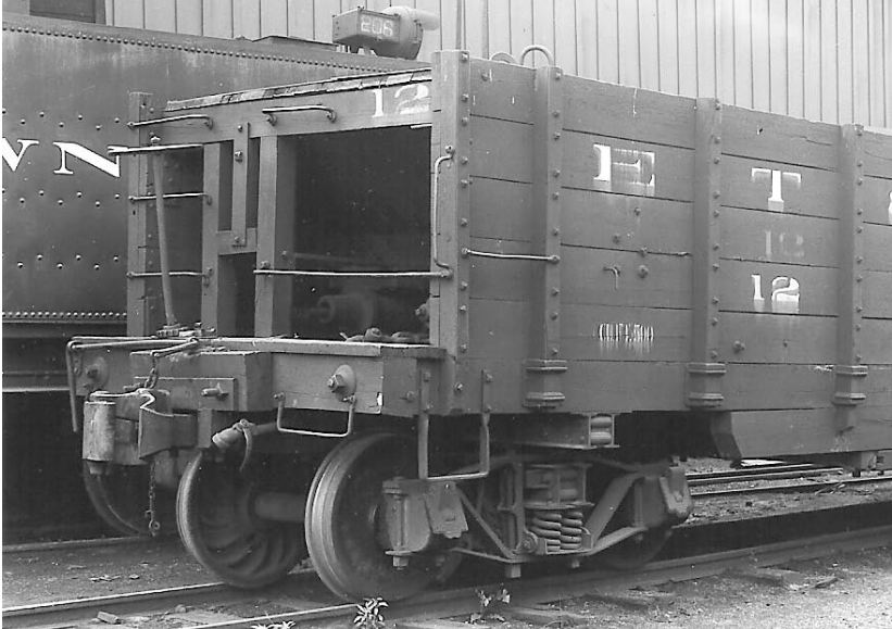
A change in plans. It’s not quite time to put the internal wooden braces on as they are too delicate while I work on the truss rods. I have some truss rod pads from Ozark that I spaced around the door openings, thus allowing the doors to open - though they will be fixed in the closed position on this model. I used 1/16" brass rods for the truss rods. I got them from McMaster-Carr since I needed something longer than the standard 12" size. McMaster has them in 36" lengths - this allows me to get 4 truss rods out of two brass rods.

(http://www.jbrr.com/Pics/RollingStock/Hopper/ETWNC/IMG_9820.JPG)

They are installed much like the real ones and go through the end timbers. The actual ones had some sort of connection just on the outside of each door, but I did not model this. I bought a 0-80 die and threaded each end to accept 0-80 nuts.

(http://www.jbrr.com/Pics/RollingStock/Hopper/ETWNC/IMG_9819.JPG)

I couldn’t find any 0-80 square nuts, so I used the Dremel on some 0-80 hex nuts to make them more or less square. These replace the plastic ones I had used earlier for the ones next to the coupler. I had bought some truss rod NBW from Ozark earlier and wanted to use the washer. I cut the nut and bolt off and filed them smooth. Then I drilled a #52 hole in each and placed them on the rods, followed by the square nuts.

Bruce,
Where did you find those “eye pins”?
What size are they?
I’ve been looking for those for a while.

Great build!

John, I got them from Micro-Mark.

(http://www.micromark.com/RS/SR/Product/60405_R.jpg)

According to them: .033 inch diameter brass, 1/2 inch long, 3/64 inch inside eye diameter. Approx. 144 pins per package http://www.micromark.com/Miniature-Brass-Eye-Pins-Pkg-of-144,7071.html Of course I can never order just ONE thing from them. They have also been very quick on delivery lately.

Finished all the truss rods today for the four cars. Each rod is threaded to accept a 0-80 nut that is filed down to be a square nut. The sequence shows the steps to take a cast washer/nut/bolt into just a plain washer.

(http://www.jbrr.com/Pics/RollingStock/Hopper/ETWNC/IMG_9821.JPG)

It also shows a few of the square nuts. Not perfect, but close enough. I also bent some brackets for the air tanks. These are glued onto the Hartford castings using JB weld. Holes are drilled and filled with my NB castings.

(http://www.jbrr.com/Pics/RollingStock/Hopper/ETWNC/IMG_9823.JPG)

…:)… Nice work What’s wrong with regular pins from say Michaels?

(http://www.micromark.com/RS/SR/Product/60405_R.jpg)

Does Michaels sell eye pins?

Yes Bruce. In the jewelry section, both brass and silver

Then Hobby Lobby would too. Bigger store in our town than Michaels.

Micro-Mark delivers! :wink:

I think I’ve got everything connected more or less correctly. I used 1/16" for the main brake line and 3/64" for connecting the tanks and main cylinder.

(http://www.jbrr.com/Pics/RollingStock/Hopper/ETWNC/IMG_9824.JPG)

I used a 1/8" x 1/32" brass bar for the main brake lever, which is just behind the support posts. I also used my delivered Micro-Mark eye pins to hold the main brake line in place. :wink: I decided to go ahead and glue one side in place. Clamps will hold it until dry.

(http://www.jbrr.com/Pics/RollingStock/Hopper/ETWNC/IMG_9828.JPG)

This is really coming along nicely, and very interesting to see.

Thanks. I wasn’t happy with the distance between the brake cylinder and the end of the car, so I moved it back for the next three cars. Since I needed six more brackets, I built a jig out of acrylic to help bend them all the same size.

(http://www.jbrr.com/Pics/RollingStock/Hopper/ETWNC/IMG_9837.JPG)

I have completed the main brake lines for the other three cars as well as the brake end sections pictured above.

Love the detail. Going to look awsome when done.

Holy Cow!!! Just amazing Bruce.
Dave

Thanks! Work continues inside, since it’s pouring rain outside. I cut the sloped floor pieces to size and notched to allow room for the beams. I also beveled the edges where they meet the beams.

(http://www.jbrr.com/Pics/RollingStock/Hopper/ETWNC/IMG_9838.JPG)

Started gluing the sides in place.

(http://www.jbrr.com/Pics/RollingStock/Hopper/ETWNC/IMG_9840.JPG)

I realized that I had not yet built the plates for the other side of the car; these are the ones that holds the rod that operates the doors. I laid 8 pieces out on a piece of .030" styrene, marking where all the holes should be drilled. I drilled everything before I broke the pieces apart as I find it easier to drill one big piece.

(http://www.jbrr.com/Pics/RollingStock/Hopper/ETWNC/IMG_9844.JPG)

This shows the plates for the operating side; they are glued in place, then I drill and install the NB castings from Grandt Line. I also installed the stake pockets I got from Ozark.

(http://www.jbrr.com/Pics/RollingStock/Hopper/ETWNC/IMG_9850.JPG)

And the other side:

(http://www.jbrr.com/Pics/RollingStock/Hopper/ETWNC/IMG_9851.JPG)

The floor is just laid in place, but I like the look of the brakes a lot better now that I’ve moved the cylinder back.

(http://www.jbrr.com/Pics/RollingStock/Hopper/ETWNC/IMG_9855.JPG)

Looking mighty sharp. I like the look