“A new Xacto blade isn’t satisfied until it tastes human blood.” Its one of Murphay’s laws of model building.
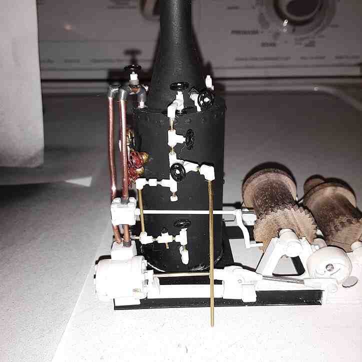
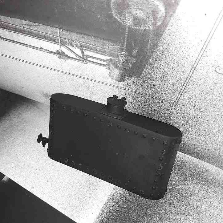
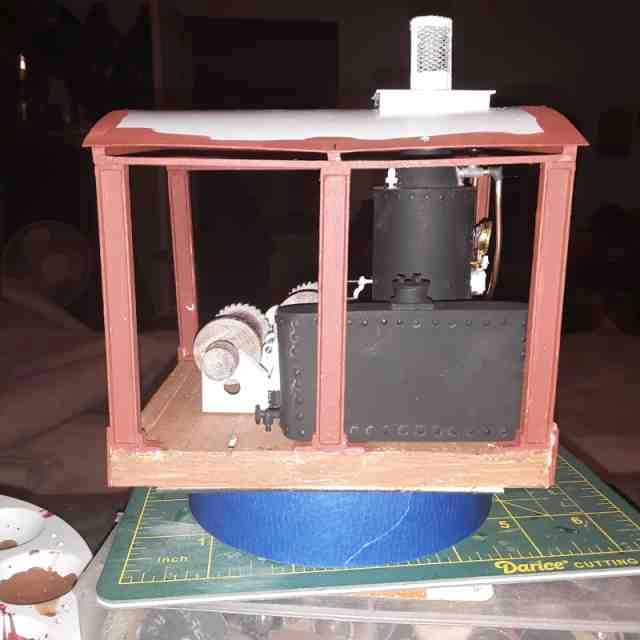
So I am done with the engine details. There is a lot that is missing but I can’t get it all in an I am done trying. I think it will show nice. Got the steam chest plumbed in, an a throttle valve built. I finished the water tank. Painted the cab floor and got a start on the super structure. I am pleased with the progress. I will have the cab done in a few more sessions.
Not sure you have any room for more details (https://www.largescalecentral.com/externals/tinymce/plugins/emoticons/img/smiley-wink.gif). The engine really looks good. How are you modeling the rivets in the boiler and water tank? You probably described it earlier in the post, I’m just too lazy to go back and look (https://www.largescalecentral.com/externals/tinymce/plugins/emoticons/img/smiley-sealed.gif).
Dang Devon, do you ever sleep?(https://www.largescalecentral.com/externals/tinymce/plugins/emoticons/img/smiley-foot-in-mouth.gif)
Mucho progress. Nice!
Dan Hilyer said:
Not sure you have any room for more details (https://www.largescalecentral.com/externals/tinymce/plugins/emoticons/img/smiley-wink.gif). The engine really looks good. How are you modeling the rivets in the boiler and water tank? You probably described it earlier in the post, I’m just too lazy to go back and look (https://www.largescalecentral.com/externals/tinymce/plugins/emoticons/img/smiley-sealed.gif).
It is super complicated. Sewing pins.
Rick Marty said:
Dang Devon, do you ever sleep?(https://www.largescalecentral.com/externals/tinymce/plugins/emoticons/img/smiley-foot-in-mouth.gif)
No. Not really. But I had a four day weekend and this is about all I did.
Really, really amazing!
Starting to think you don’t belong in this challenge, I think you need to go play with the big kids!!! Great work
Bill Barnwell said:
Starting to think you don’t belong in this challenge, I think you need to go play with the big kids!!! Great work
If I ever thought I could convince the wife to let me do it, I had an idea for a backyard BBQ that would be a function 1/4 scale steam donkey. I would love to work in 1:1.
I do believe I have her sold on letting me make a copper pot still. Don’t tell the revenuers!!!
Engine detail is amazing, I like!
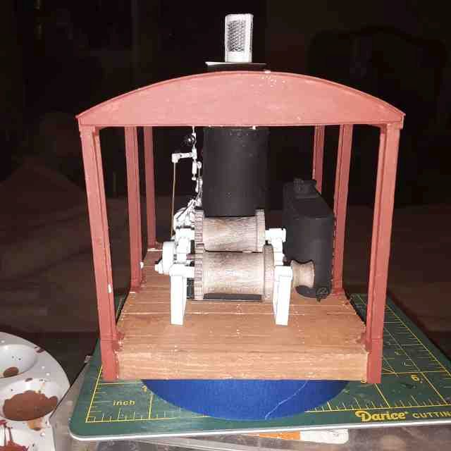
Dang it. Just realized a detail I had intended to add and didn’t. It needs stay rods from the boiler to the front drum mount. I can get those in I think. I’m gonna add a Johnson bar as will but that will be mounted tot he floor.
Rick Marty’s is almost as good as yours Devon…

I don’t know that looks better than mine. Way more detail. The fact that you are suggesting that I am anywhere near Rick’s ability is flattering. I have decided just once, I need to sit down and build something, anything, with commercial detail parts just to see if I can make a “museum” quality model. I really think I can. But what interests me more, and Rick does an excellent job of this as well, is what I can create out of stuff that was never meant for modeling. I think thats why I love the MIK challenge so much. I think I would have really enjoyed Allen’s stuff. Its far more rewarding to me to build from scratch and have a mediocre model made from nothing. The late Dick Whitney who was a lurker here and a friend of mine (to late in his life to fully appreciate him), was an amazing detail modeler. And he bought very little. He made things from cereal boxes and window screen. He made parts, then molded them, and then reproduced them. He was/is my inspiration. Rick Marty, Ray Dunakin, Jon Radder, Eric Schade, and so many others on here are such talented modelers on here that are specialists into turning bits and pieces of nothing into something. I only hope to aspire to be mentioned in with a league of greats.
Devon Sinsley said:
I don’t know that looks better than mine. Way more detail.
You said you were not done yet…
Devon Sinsley said:
So I am done with the engine details. There is a lot that is missing but I can’t get it all in an I am done trying. I think it will show nice. Got the steam chest plumbed in, an a throttle valve built. I finished the water tank. Painted the cab floor and got a start on the super structure. I am pleased with the progress. I will have the cab done in a few more sessions.
Devon, I have done piping before using small brass rod of paper clips shoved into hollow styrene tubing and finished off with small undersized 2/56 nuts placed over the styrene to look like plumbing fittings, but was wondering how you made your elbows and t’s that become valves, Thanks Bill
Basically the same exact way as you are describing Bill. On this project I used two different materiel to achieve the same effect using the same concept. And I have perfected/still perfecting the technique. But here is a simple run down and I am thinking about doing a tutorial on this. It could be used here and my local club is looking for things like this for our new letter. So it will be worth it to do it. But for now here is what is going on.
Originally I used styrene tubing and brass wire. For an elbow you cut the tubing at 1/2 the angle of the elbow you are wanting. So a 90 degree elbow means cutting the tubing at a 45, then rotating on side 180 degrees and gluing them back together. I then inserted the wire in each end. This works and once the styrene welds itself back together and dries is decent looking but still not very strong. So the I was thinking on it and decided if I could make this all on one continuous wire it would use the wire for strength instead of the weld joint. This worked out excellent. For a 90 you bend the wire at a very sharp 90 degree bend, trying not have it be rounded but a sharp corner, and then sliding the halves of the elbow together and gluing. It gave a very nice 90 and a strong one.
Now I used Rick’s suggestion of 14 gauge romex wiring to act both as the pipe and fitting (insulation) and it works good but can’t get as sharp a bend as I would like. I will play with that more.
Tees and valves are made basically the same. A long piece of plastic tubing acts as the body and then a Piece is cut and radiused using a round file on one end and then glued to the side of the body. For the valves then you insert a valve steam and use an HO brake wheel or a sewing snap for a handle. For Tees you are still relying on the glue joint for strength. I drilled through the tee into the through piece and glued it up and that gave it more strength.
I think to go over the top in strength the Ts can be soldered bare wire and then all the elements slid into place. This would also make the Romex into sharper corners. A solder joint along withthe welded plastic should give plenty of strength.
Devon Sinsley said:
Basically the same exact way as you are describing Bill. On this project I used two different materiel to achieve the same effect using the same concept. And I have perfected/still perfecting the technique. But here is a simple run down and I am thinking about doing a tutorial on this. It could be used here and my local club is looking for things like this for our new letter. So it will be worth it to do it. But for now here is what is going on.
Originally I used styrene tubing and brass wire. For an elbow you cut the tubing at 1/2 the angle of the elbow you are wanting. So a 90 degree elbow means cutting the tubing at a 45, then rotating on side 180 degrees and gluing them back together. I then inserted the wire in each end. This works and once the styrene welds itself back together and dries is decent looking but still not very strong. So the I was thinking on it and decided if I could make this all on one continuous wire it would use the wire for strength instead of the weld joint. This worked out excellent. For a 90 you bend the wire at a very sharp 90 degree bend, trying not have it be rounded but a sharp corner, and then sliding the halves of the elbow together and gluing. It gave a very nice 90 and a strong one.
Now I used Rick’s suggestion of 14 gauge romex wiring to act both as the pipe and fitting (insulation) and it works good but can’t get as sharp a bend as I would like. I will play with that more.
Tees and valves are made basically the same. A long piece of plastic tubing acts as the body and then a Piece is cut and radiused using a round file on one end and then glued to the side of the body. For the valves then you insert a valve steam and use an HO brake wheel or a sewing snap for a handle. For Tees you are still relying on the glue joint for strength. I drilled through the tee into the through piece and glued it up and that gave it more strength.
I think to go over the top in strength the Ts can be soldered bare wire and then all the elements slid into place. This would also make the Romex into sharper corners. A solder joint along withthe welded plastic should give plenty of strength.
Thanks so much your build is just outstanding, Thanks again, Bill
Oh #%$^ someone said we are half way to the deadline!!! Not cool.
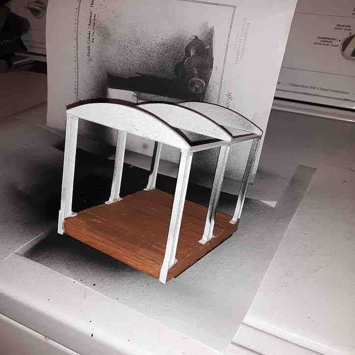
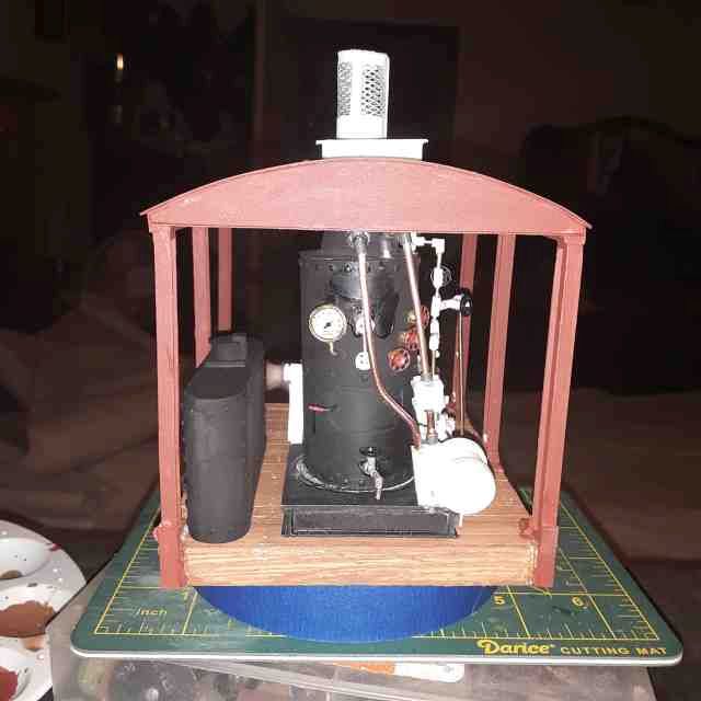
I got the cab sub roof on and painted the superstructure and made a roof hatch. I test fitted the engine and water tank and I am liking what I got. Next step is to get the engine out and get it painted. I need to put on my custom ordered Taylor Tin roof. Add a couple of cab details and then reinstall the engine and I think the cab will be done and I can move to the car. How the car mates up to the Foreman’s car will be a big determining factor on boom length.
Looking good Devon. The amount of time you have spent on the details was time well spent from my perspective. Just don’t hide it! Your public demands to see it!
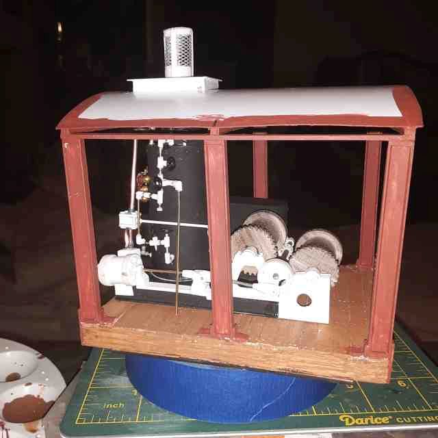
Is the engine (most importantly the drums) centered? Seems like for best operation you would want the drum centered on the boom. Or am I confused? Other engines I’ve seen have the water tank behind the engine and the engine centered.