Large Scale Central

Devon's 2019 MIK build- steam crane

Next on the list was to make the friction drums. A lot smaller discussion. But it is the next part of this model that I made.

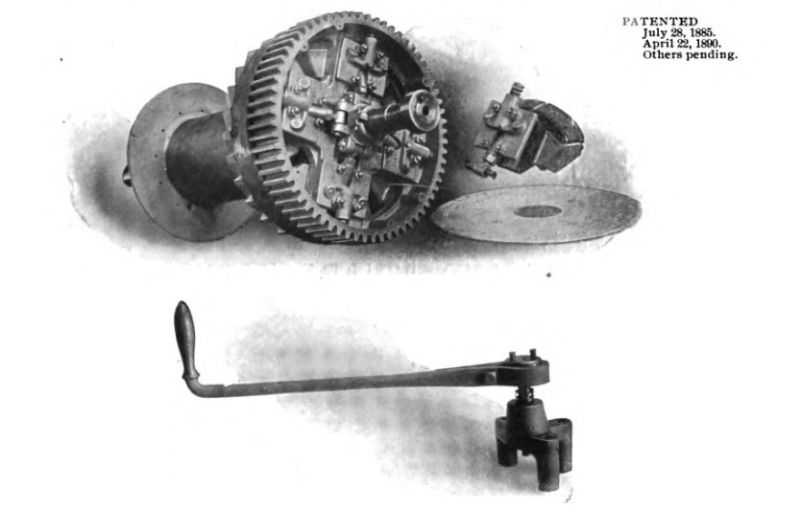
I first wondered why they were called “friction drums”; as I figured this had something to do with either how they were held in place under load or referred to how the cable was held onto them. Wrong on both counts. It refers to how they are driven and explains to me how two or more drums could be operated off the same engine at different times. It also explains why each drum has a handle (shown above) on the end of each drum shaft. So the big gear on the end of the drums is in contact with the smaller gear on the drive shaft which is connected to the steam cylinders via the connecting rod. When the drive shaft turns it then turns all of the gears on all of the drums but does not turn the drums themselves. The operator begins to crank on the handle which pushes friction blocks (in the case of the prototype are made from hardwood) outward from the shaft and comes in contact with the inner surface of the spinning gear. As it comes in contact friction grabs the spinning gear and begins to turn the drum. it can be a limited slip affair or clamped all the way down for positive grip giving the operator control over the drum. The top part of the picture shows the four friction block mechanisms surrounding the shaft and a small example of just one of those friction blocks. Pretty ingenious design. The saw blade thing to the inside of the gear is the brake ratchet thingamajig. As the drum spins a ratchet pawl clicks into place on each tooth. When the friction on the drum is removed the ratchet locks the drum in place. A brake handle releases the ratchet and allows it to be moved in the reverse direction again being held by friction to control it its drop. Or the engine itself can be reversed and drive the drums in reverse. Each drum is fitted with friction blocks and ratchet thingamajig for independent control over each of the separate drums.

In addition to the drums themselves many of these hoisting engines have additional capstan winches or gypsy style winches on the sides. These are what I was thinking when I thought “friction drum”. A rope is wrapped around them with the operator taking hold of the loose end. the rope is not wound around the drum as much as is just given a wrap on it and the loose end piles up at the operators feet. When the operator puts tension on the loose (tag) end of the rope it tightens the rope on windlass (drum) and friction bites the rope and begins to haul it in. Speed is governed by how much friction or thus how tight the rope is on the drum. This can be used when a permanent attachment of the rope is not desired but you need the pulling power of the steam engine. Now what I don’t understand is how this winch and the drum which appear to me to be on the same shaft can be operated separately. How does the winch spin and not move the cable on the drum. Considering it is the gear that is spinning all the time and not the shaft. Unless there are more than one shaft one attached to the gear and over to the winch and an outer one that is attached to the cable drum?

I did not get the ratchet thingamajigs on my drums. I will need to figure out a way to add them. Sure wish I would have noticed this earlier when I was turning them. Oh well I will find a way.

The gypsy style drums are the same style used in old hay boom loading snd unloading bales of hay off trucks. The boomer” not to be confused with Boomer, controled the bales rise or decent by pulling on the rope . Used to watch them unloading at a dairy I worked at.

I have used a gas powered one to haul a few elk put of deep canyons

So here is a very small update on progress. I am just not going as fast as I think I should be. But oh well.

Painted the fiddly bits on the boiler that are installed already. I have a lot more of them to go. I also started building up the frame that the engine is built on. And made up the side frames for the top drum. Need to figure out how to install the saw blade whatchamacallit that is the part of the ratchet mechanism that goes on each drum as an after thought. Right now I am working on the steam cylinders. Thanks to the discussion on valve gears I think I have all the information I need to get all the parts and pieces put together.

Good progress Devon.

The locking thingy on the drums your talking about is the locking dog. A small lever trips into the teeth of the ratchet on the drum and locks the drum from back spooling.

Your posting good information on the vertical boilers and engines, keep it up. It is fun researching them, even more fun operating them(https://www.largescalecentral.com/externals/tinymce/plugins/emoticons/img/smiley-foot-in-mouth.gif)

Hey Devon, You do know we have 30 days to get these things built??? You don’t have build all in one week (https://www.largescalecentral.com/externals/tinymce/plugins/emoticons/img/smiley-wink.gif). Thank you for all the detail you are putting into your build and sharing it with us. I am following and taking notes. Boiler is looking good. I really like the paint job. Makes it look like it has been used quite a bit.

Rick since you are familiar with the real deal can you answer my query on how the windlass on the sides of the friction drums are operated? Seems to me they are attached to the same shaft as the drum itself. But this can’t be because as I am thinking about it if you tried to use the windlass you would be also turning the drum spooling or unspooling the cable. They have to be operated independently. So how are they attached to the drive shaft being they are on the ends of the drum.

Dan,

You think I am moving fast and I am already afraid I am not gonna make the deadline. This thing is gonna be all about the details. I had hoped to have the entire engine done by now. If I was building only a steam donkey I would be doing fine. But that is only one part of a much larger crane.

I feel like maybe I have bit off more than I can chew

If the friction blocks aren’t driving the drum, and the locking dogs are locked, then why can’t the same shaft be used for driving the windlass?

David Maynard said:

If the friction blocks aren’t driving the drum, and the locking dogs are locked, then why can’t the same shaft be used for driving the windlass?

Because unless I am missing something the big outer gear is what is continually spinning. Not the shaft that the drum and windlass are attached to. As the friction blocks are engaged then the shaft upon which the drum and windlass are attached begins to spin. The locking dog would make no difference as it only "locks the drum from free spooling backward and transfers no motion itself. Unless I am very wrong about which parts are doing what. The cylinder is connected to the con rod which is connected tot he flywheel which is connected to the drive shaft which is connected to the small sprocket which is connected to the large sprocket/gear on the end of the drum. So when this thing is fired up and the cylinders are operating that means the big gear on the drum should be spinning but the drum won’t spin until the friction block is engaged which then in turn spins the shaft that the drum is on. If the windlass is also attached to that shaft as it appears to me then it would spin at the same time as the drum. Now I don’t believe this is the case, but what am I missing? how is the windlass separated from the drum or in other words what is connecting it to the drive shaft independent of the drums?

Hey! If all ah dis is goin to be inside a crane house, den does any of it matter? Its gonna be hidden frum view anyway. (https://largescalecentral.com/externals/tinymce/plugins/emoticons/img/smiley-wink.gif)

David Maynard said:

Hey! If all ah dis is goin to be inside a crane house, den does any of it matter? Its gonna be hidden frum view anyway. (https://largescalecentral.com/externals/tinymce/plugins/emoticons/img/smiley-wink.gif)

Well that much is very true David. It is so well hidden that after pouring over pictures of the damn things half taken apart I still can’t see what is going on. So on my model I will have no trouble making it convincing at least. But not knowing bugs the heck out me.

Despite Pete’s recommendation that I leave details for later, I ignored him and made some more details on the boiler. I worked on the feed water injector. As promised I made all the fittings and plumbing from scratch. Its time consuming, doesn’t look as nice as fancy detail parts, but is very rewarding, a last for me, to be able to replicate complicated plumbing arrangements.

Here is the prototype

I made the small line in the center which works as the injector.

Oh yeah I also made some smaller handles for the sight glass cocks.

No to bad, not perfect, but not bad.

Looking really good. Did you make all the fittings (elbows, valves) out of styrene rods?

How does the smoke get out?(https://www.largescalecentral.com/externals/tinymce/plugins/emoticons/img/smiley-wink.gif)

Jim,

The fittings are all styrene tubing. The pipe is brass rod. Valve handles are sewing snaps. 90s are made by cutting the tubing at a 45 spinning the two halves 180 degrees and regluing. Tees are made but using a round file and on the end of a piece. Then gluing that to the side of another piece. Valves are made like tees with a piece of styrene rod glued into the snap hole and then into the Tee. At the bottom there is a globe check valve made like a tee with a square head bolt glued in the 90 degree hole and a piece of brass rod inserted into a hole drilled into the bottom for a drain cock.

John Caughey said:

How does the smoke get out?(https://www.largescalecentral.com/externals/tinymce/plugins/emoticons/img/smiley-wink.gif)

Isn’t that a great boiler???

Devon Sinsley said:

Despite Pete’s recommendation that I leave details for later, I ignored him and made some more details on the boiler. I worked on the feed water injector. As promised I made all the fittings and plumbing from scratch. Its time consuming, doesn’t look as nice as fancy detail parts, but is very rewarding, a last for me, to be able to replicate complicated plumbing arrangements.

Here is the prototype

I made the small line in the center which works as the injector.

Oh yeah I also made some smaller handles for the sight glass cocks.

No to bad, not perfect, but not bad.

I can see were this is going…

Image result for three stooges bath tub plumbing

Just plain OUTSTANDING!!!

If there is interest in my plumbing techniques I would be glad to throw together a little tutorial and post it on the modeling page. They really are easy to do and Are fairly self explanatory, but if someone wants to see it I will do it. One thing I thought about last night while doing this (that one configuration took about two hours) is that all of my pieces/parts are too big for scale. Another problem I have is the ratio between pipe size and fitting size is wrong. I am being picky I know, but that stuff does bug me a little, its the rivet counter in me. I have some stuff that is steel rod coated with styrene that the coating can be removed leaving just the wire. I think using that stuff and a smaller diameter tubing (which I don’t have on hand) would make for a better over all scale size and also a better ratio between pipe and fitting. After the MIK build I might work up some plumbing and refine the technique and post something if people want to see it.