Large Scale Central

Devon's 2019 MIK build- steam crane

That steam shovel/ditcher is way too cool.

I have been way to anxious about getting started. So as I have been going through my junk to see what I might want to use, I came across a 1/24 30’ flat car kit from Big Train Backshop. It’s part of the stuff from my late friend Dick Whitney. I decided to build it as a prototype for the flat car that the crane will sit on. I will use the same plans and use or cut new wood and use my own details. I will use this car to carry rail.

I wish we had a year to build this. I think this would make a nice crane.

Oh come on, Devon! Go for it! I particularly like the various tools/weapons attached to the walls (sword, shovel, etc.)… Somehow this reminds me of Mortal Engines…

Devon Sinsley said:

I wish we had a year to build this. I think this would make a nice crane.

But, but, Devon … you don’t have a third rail (https://www.largescalecentral.com/externals/tinymce/plugins/emoticons/img/smiley-sealed.gif). Its going to be a bumpy ride with that front, center wheel running across the ties.

That job should use up the coffee stirrers thats been hanging around for years!!

Well I got a bit of a start this morning on the boiler. Started out cutting a piece if 1" PVC pipe and a chunk of black walnut. Turned the walnut on the lathe to fit the pipe. After this picture I made a drill template and drilled the boiler and used sewing pins for rivets and added a fire door.

I will have some time between games to do some more work.

But then it was off to sons hockey tournament.

Good start, Devon. You did a good job with the lathe. I’ve got to get me one some day soon.

So a little more progress on the steam engine for the crane. I am loosely following an American derrick engine. Double cylinder, double friction drum, with a single winch head. Here is the work so far on the boiler.

The stack will be cut down and fitted with a screen once I know where the roof will be. I am in love with the paint I am using. I always used a rattle can flat black but it was never really quite right. This is chalk board paint in a rattle can. Its a very flat black with almost a little be of a grey hue. and since it is made for chalk it has a little texture to it. The more I touch it and handle it the more it weathers itself with the dirt and oil from my hands.

Here are the drums turned on the lathe from walnut and then using a file I carved the gears into it. Much slower start than I expected.

That looks terrific, Devon! I need to build a similar engine for a future project. This is going to be a great resource for me.

Where did you get the valve handles/wheels? I presume you didn’t whittle those? Why are there 3 of them? Just looked right or is that prototypical (and if so what do they do)? I actually ordered a book about these kinds of steam engines so I could understand what all the piping and other mechanisms are like because I’m pretty clueless. Oh yeah, I’m also looking for pipe fittings. Any pointers?

Devon Sinsley said:

So a little more progress on the steam engine for the crane. I am loosely following an American derrick engine. Double cylinder, double friction drum, with a single winch head. Here is the work so far on the boiler.

The stack will be cut down and fitted with a screen once I know where the roof will be. I am in love with the paint I am using. I always used a rattle can flat black but it was never really quite right. This is chalk board paint in a rattle can. Its a very flat black with almost a little be of a grey hue. and since it is made for chalk it has a little texture to it. The more I touch it and handle it the more it weathers itself with the dirt and oil from my hands. …

Of course! Chalkboard paint! Why haven’t I ever thought of that?

And the boiler looks perfect Devon. Great stuff.

edit: actually, let me amend that…it looks damn near real.

Jim Rowson said:

That looks terrific, Devon! I need to build a similar engine for a future project. This is going to be a great resource for me.

Where did you get the valve handles/wheels? I presume you didn’t whittle those? Why are there 3 of them? Just looked right or is that prototypical (and if so what do they do)? I actually ordered a book about these kinds of steam engines so I could understand what all the piping and other mechanisms are like because I’m pretty clueless. Oh yeah, I’m also looking for pipe fittings. Any pointers?

Cliff here are some answers to your questions. And as I build it I will try and explain what the fiddly bit are as I put them on and their function as I know and understand it. However, I am by no means an expert, far from it, still very much a student still. Start here, this is a link Cliff Jennings provided in the reference section under my post about the Hathi Trust online library. It is a catalog for the American Hoist and Derrick Co. and their derrick engines. The drawings are excellent and quite helpful in modeling it.

The valve wheels are HO brake wheels. Another source for good looking handles are sewing snaps.

Now as to why there are three of them; these are tri-cocks (don’t worry we are not talking about having to have three roosters). In addition to a sight glass which visually tells you the level of water in the boiler, Tri-cocks are are usually globe valves that are cracked open to allow water to drip from them. If the top one is dripping then the boiler is full. If the middle one stops dripping you need to be paying attention. If the bottom one stops dripping y.u may want to run because a boiler explosion is immanent. A boiler that is very full to over full leaves little area in the boiler for steam and the effectiveness of the boiler is reduced. You want the water such that there is head space for the steam to build up with out it being so low that it exposes the crown sheet which is the top of the fire box. So the sight glass and the tri-cocks help the operator know exactly where the water level is in the boiler. This also appears on the boiler backhead of steam locomotives. These HO brake wheels and even the snaps are a great in 1:20.3 but can be a little large for the 1:24 I am after but I am not that picky.

I will be making all my pipe fittings for the MIK challenge. But Ozark Miniatures, Precision Scale Company, and Trackside Details all make excellent cast plumbing fittings that would be excellent to work with. Here is a boiler backhead I did making my own fittings and using snaps for handles.

Notice the same three valves on angle, the tri-cocks. Oh another word on tricocks if it wasn’t obvious. The top one is inline with the top of the sight glass, the bottom one is inline with the bottom of the sight glass and the middle is in the middle. On my backhead my sight glass needs to be longer. If you are interested in making your own I have a copy of a great tutorial on making them that I robbed from a MLS master class. I’d be happy to email it to you. Also the rivet details are sewing pins.

Thanks Devon. Very helpful.

many boilers have a tri-cock set up. 3 Valves that open downward, usually into a drip pan. These are a double check for the water level in the boiler. Crack one of the valves open, if it dribbles hot water, then the water level is above the level of the valve. If it emits steam, then the water level is below the level of the valve. And its not a good thing when the lowest of the tri-cocks emits steam.

Devon, that looks excellent. I mean, with the right photo setup, it would look real just as John pointed out. And thanks for the discussion on the tri-cocks. It looks complicated, but after your explanation it is quite a simple idea.

wow you are raring to go, 1 full day in and lots of progress!! Makes me wish I could do something!

Gee Pete and here I feel I am way behind. I figured I would have the Derrick engine almost complete by end of this weekend. I am just getting started on the cylinders

Pete Lassen said:

wow you are raring to go, 1 full day in and lots of progress!! Makes me wish I could do something!

You can’t drive 24 hours so what’s your excuse? I used to bring stuff with me when I worked for BNSF to do in the hotel. I built a handful of HO and N scale trees while sitting in a hotel. Now the back of your track cab might not be as spacey, but I’m sure you could come up with something?

I have to agree with Craig on this one. I will be in Wenatchee next weekend for another hockey tourney but I assure you my supplies are coming g with me.

Forgive me for hijacking my own thread; but I love to learn and Jim asked about the fiddly bits on these boilers/hoists. Admittedly I am only somewhat familiar with these iron beasts and how they function. As I do in all my modeling I use it as a lesson on understanding what it is I am trying to replicate. I could simply glue the fiddly bits in the area that I see them and call it good. But what the fun in that, I would rather know what the fiddly bits do. So to that end and to help myself, Jim, and anyone else i am going to use my MIK build as a tutorial on not only building one but understanding what it is we are building. So for those who already know, feel free to correct me, add to it, or simply ignore it. So here it goes, the heart of the beast, the boiler.

A boiler is a relatively simple thing and it makes no difference if it is a locomotive, a tractor, a ship, a crane, or a steam donkey; the boiler is a boiler. It consists of a fire box, a water/steam tank, and a smoke box. In our example here the fire box sits on the bottom and as the name implies is where the fire is built to heat the boiler. The boiler itself is a tank that holds the water and steam. It has a series of tubes running through it that heat and gas/smoke move through on their way to the smoke box and eventually out the stack/chimney. As the heated gas/smoke moves through these tubes it heats the surrounding water to the boiling point creating steam. There are a great many tubes as this increases surface area and contact with the surrounding water. That’s boiler basics 101. The steam produced is then used for various things, the main one in our case is to drive a piston to create motion. In this little post I will do my best to explain what each of the pieces on the boiler are so that we can know what we are modeling.

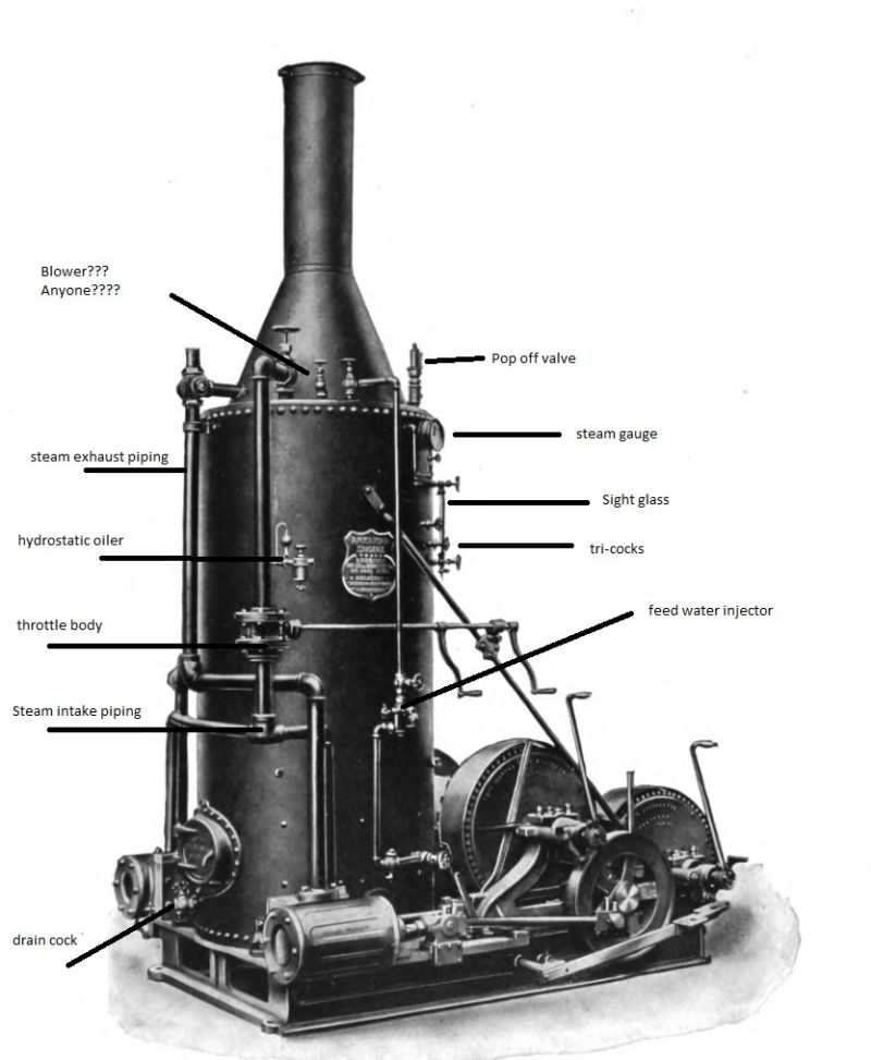
Starting at the top. The thing I have labeled blower, I am not actually sure if this is what it is or not, acts like a turbo charger. If this is what I think it is, and they do use them extensively on locomotives, the fire is increased with draft. On a fire place we open and close dampers to create draft. In a boiler this is accomplished by air entering the fire box and then being sucked out the stack. To give this a little (well a lot actually) boost exhaust steam is ejected through the smoke box and out the stack. As the steam rushes out the stack it acts like a venturi sucking air/smoke through the fire box, through the fire tubes and out the stack. This really increases the draft and fans the fire. Under operation this is done with the exhaust from the steam chests being dumped into the smoke box instead of just out to atmosphere. When the engine is not being used, i.e. when the throttle is closed and no steam is going to the chest, there is a blower that takes steam of the top of the boiler and injects it into the stack thus doing the same thing, turbo charging the draft. Now in this drawing I can only guess that is what that fiddly bit is I am pointing too.

Pop off valve- a valve set at a predetermined pressure setting that opens automatically at the set pressure allowing steam to escape so as to prevent over pressurization and an explosion. Locomotives a lot of times have two set at different pressures as a double safety. If you want a real example go look at your hot water tank and at the top there is a brass cylinder plumbed in. Guess what that is. BTW when that thing is leaking, please don’t be an idiot and take it off and plug it, yes people really do do this.

Steam gauge- tells you the boiler pressure.

Tri-cocks/sight glass- we discussed that above already.

Feed water injector (my name not the technical name)/ lifting injector- This is used to put water from a tank into the boiler while the boiler is under pressure. Water in the tank/tender is non pressurized. The water in a boiler under operation is under pressure. Physics dictates that substances under pressure seek to be under lower pressure. So if we were to just open a feed water valve the steam/water under pressure would head to the lower pressure of the tank/tender. So how do you overcome the pressure differential and defy physics and put lower pressure water into a higher pressure vessel. Some dude way smarter than me created the lifting injector. High pressure steam is passed through a venturi to the smoke box creating an even higher pressure zone by the accelerated steam. This venturi creates a suction, that suction is then attached to a hose/pipe that is attached to our tank. The pressure at the venturi is greater than that of the operating pressure of the boiler. So the water in the tank (well only at the point of the venturi) is greater than that of the boiler and therefore the new water wants to go to the point of lower pressure which is the boiler. Its rather simple really until you actually try and understand the physics of a venturi. But I have no intention of tackling that one. For modeling purposes you have a pipe from the lower boiler area to the injector and through the injector to the top (empty part) of the boiler. another pipe/hose is connected to the side of the injector that runs to the tank. Valves are located at the intake and the outlet for isolating the thing and another valve is located at the high pressure side which is used to turn the injector on and off and controls the feed rate.

Intake plumbing to the steam chests- steam is taken off the boiler and is fed to the steam chest providing the steam to drive the cylinder piston.

Exhaust plumbing- takes steam off the cylinder on the exhaust stroke and send it to the smoke box to drive the turbo effect mentioned earlier.

In modeling both the above pay attention to where each pipe is going. The intake is coming of the top of the boiler and goes to the steam chest. The exhaust comes off the cylinder and goes to the smoke box.

Throttle body/valve- a valve is placed on the intake plumbing to regulate the amount of steam allowed to be delivered to the steam chest. On a locomotive this is done inside the steam dome and has a rod that passes, in general, to the backhead where there is a lever that the engineer operates. On our derrick engine it is a valve operated by a handle that somewhere in the middle of the intake pipe. Turning the handle opens and closes the valve. Some have two handles as shown in this picture and I don’t understand why, anyone?

Hydro-static oiler- Also in this picture you see a hydro-static oiler. Not a 100% sure why this is there other than it has to be an added feature used for oiling various pieces of machinery automatically through connected lines. The picture shows no such lines. But they maybe passing through the boiler to heat up the oil to make it flow easier and is thus out of sight. This is how it is done on many locomotives. Steam is used to pressurize the oiler. Again by venturi, oil is sucked out of a reservoir (teardrop looking globe on top) and pushed to where it needs to go. Somehow though the oil and steam are not mixed. I can’t say as I know exactly how the steam creates a pressure and then transfers the pressure to the oil without the two mixing. I am guessing some sort of diaphragm. On a loco this was a gigantic help. Do you know why on the sides of locos you have walkways, well there are many reasons, but in the first days one of the reasons was so the brakeman could walk out and put oil in the oil cups on the steam chests while the locomotive was moving. The Hydro static oiler , took thick oil and ran it between the boiler and the boiler jacket to heat up the oil making it flow better and then dumped it into the oilers on the steam chest. No more need to manually oil the cylinders. I have always said “necessity is the mother of invention, but laziness is the father of efficiency.”

Finally the drain cock- at the bottom is a pretty self-explanatory piece of plumbing. It is simply a drain to drain the water when not under pressure for maintenance on the boiler.

So there you have it. The anatomy of a boiler inbthe most simplistic fashion as I could make it.

Excellent write-up Devon. Thanks a lot!

As an aside, here’s the link to a document [link] that Devon sent to me that goes into great detail about all the parts used to build one of these things…

[edited to make the link more obvious]