This should be a requirement, a washing machine picture or points will be deducted!
You could put him in there
Today was a lesson in sometimes doing it by hand is best.
I spent about an hour setting up my ancient Craftsman router table complete with a nearly zero clearance throat plate made from an old sheet of acrylic…
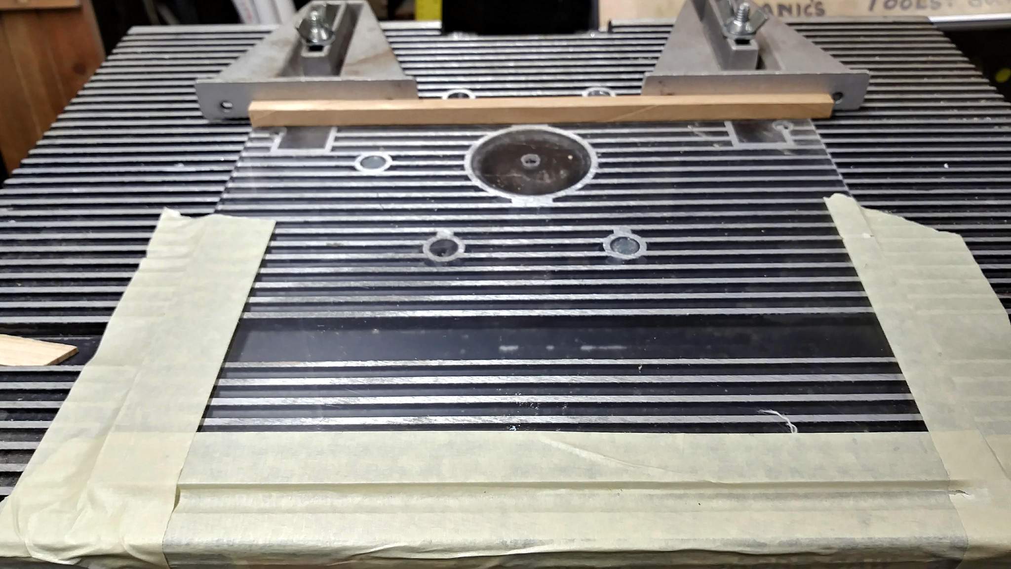
But even with s super sharp V-Grove bit set as shallow as I could get it, I wasn’t happy with the result. The grove was just too wide…

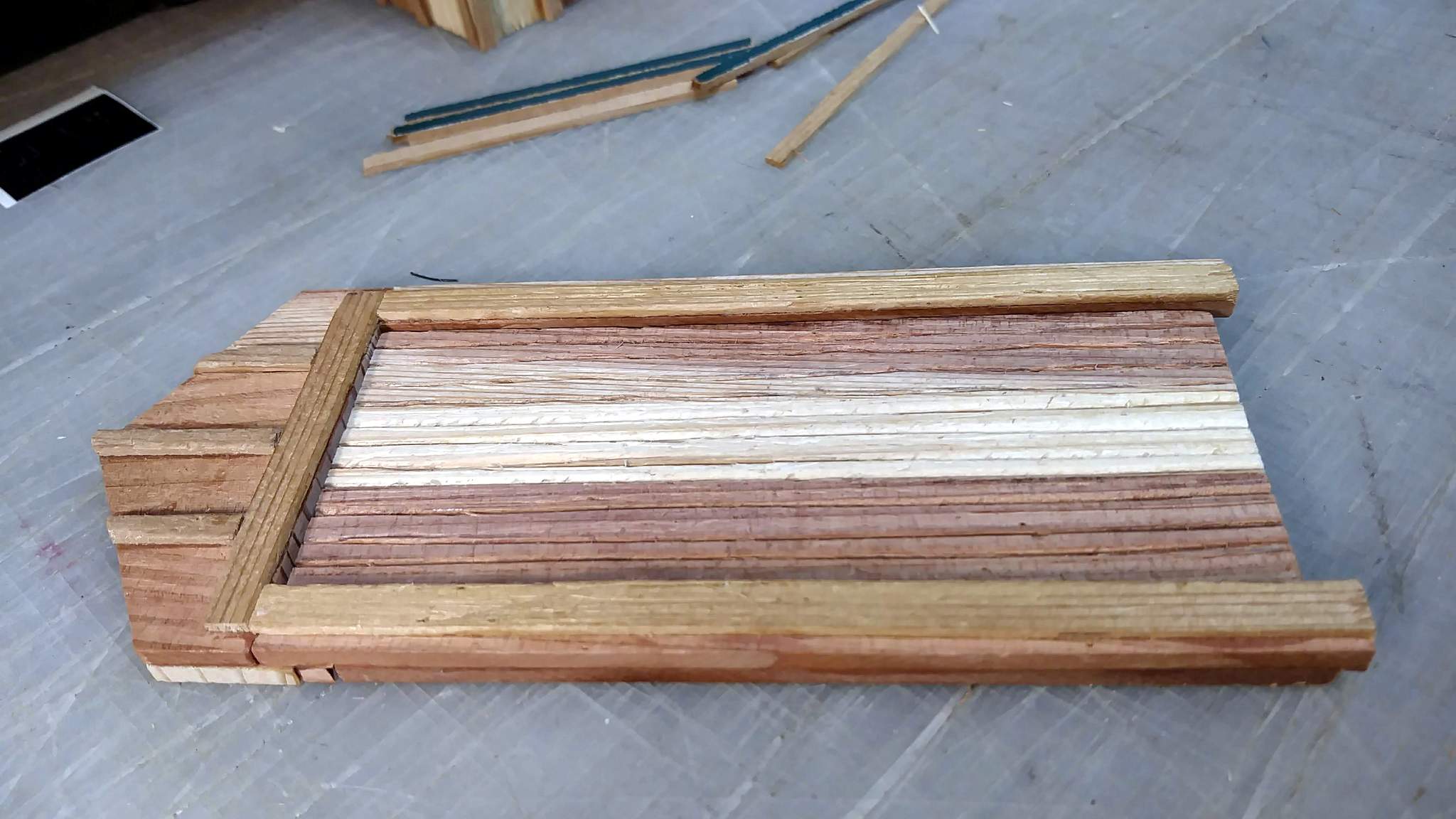
So next, some experiments using a knife and a metal ruler…
I couldn’t keep the ruler tight to the work, so I decided free-hand was s better plan. I free-hand cut lines on paper at work regularly, so I know my hand is steady enough. So I drew out lines in pencil…
Then did one pass with a sharp exacto, followed by several passes with Grandma’s manicure tool and a final clean-up with the knife. I erased the pencil lines then hit the whole surface with an old wire bush from both ends, top to bottom. A final cleanup with a stiff brush and I’m calling it done…
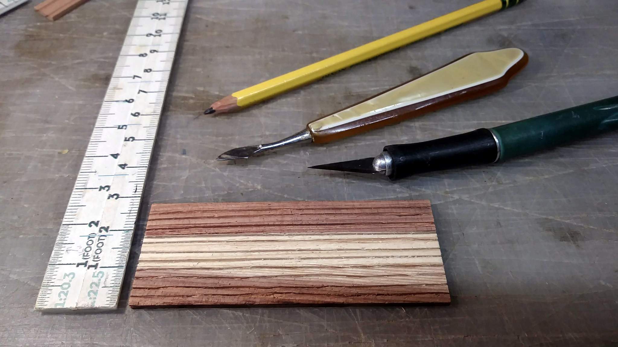
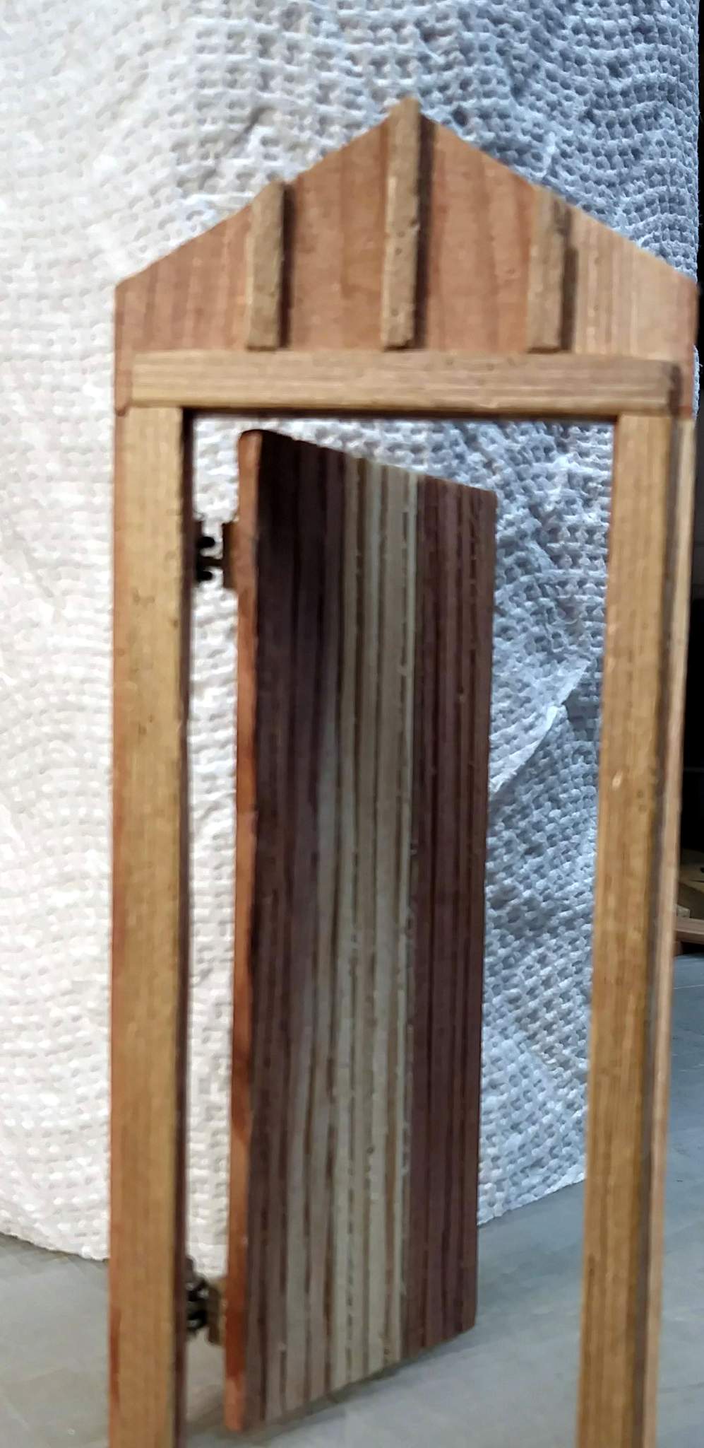
The lines came out less than perfect as the knife tip wandered with the grain. That doesn’t bother me as it’s supposed to be old and could very well be warped and cracked. In the frame…
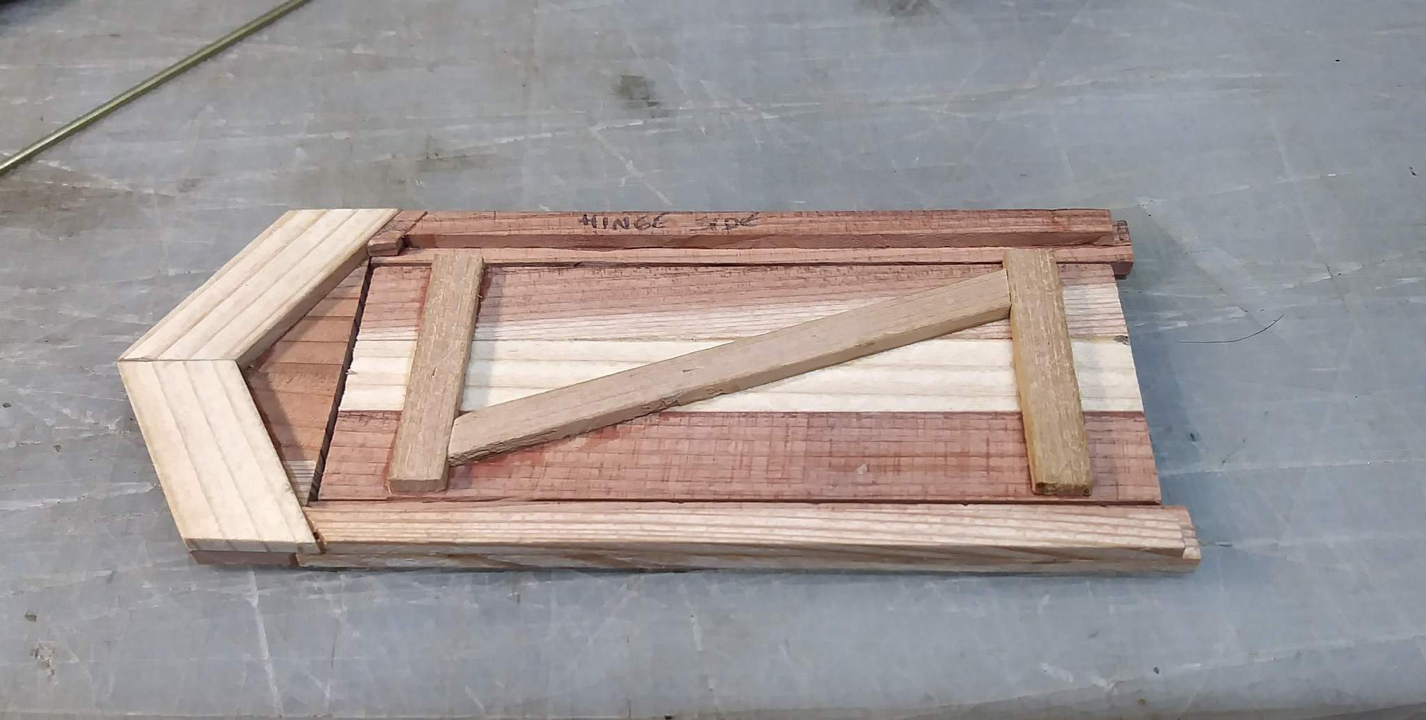
I’m going to add a Z brace on the back. It won’t be seen, but after slicing into the face I’d like a little reinforcement. And I’ve decided the fabric hinge will be perfect UNLESS I can figure out a way to make the roof removable.
Jon. I think the free handed lines add character and age to the building. Ya done good.
Think of it as using scrap wany edge boards to make a small building!
Now I see what you were trying to attempt. I didn’t have it in my head when you were talking about it. About the only other way that I could see making the V grooves like you are trying would be to set a table saw blade to 45 and lower it down to the point where only the outer edge of the top set of teeth of a carbide blade hit the board.
Not even sure if that is possible I have never tried it. But since most carbide blades for a saw have a left and right side set of teeth and each tooth is “pointed” toward the outside I would think if one lowered a 45 degree blade to where it just barely hits a piece of wood I would think that only the one set of teeth would strike it and then when it does give it a V pattern. I can see I need to do some experiments.
I don’t want to derail your thread so I posed the question in the tools and tips Simulating V grooves for tonuge and groove
I think that a full size saw would have the same issue as the router, just too big for T&G in this scale. NOW, If I had the better mini table saw with the tilting arbor THEN your idea would probably work.
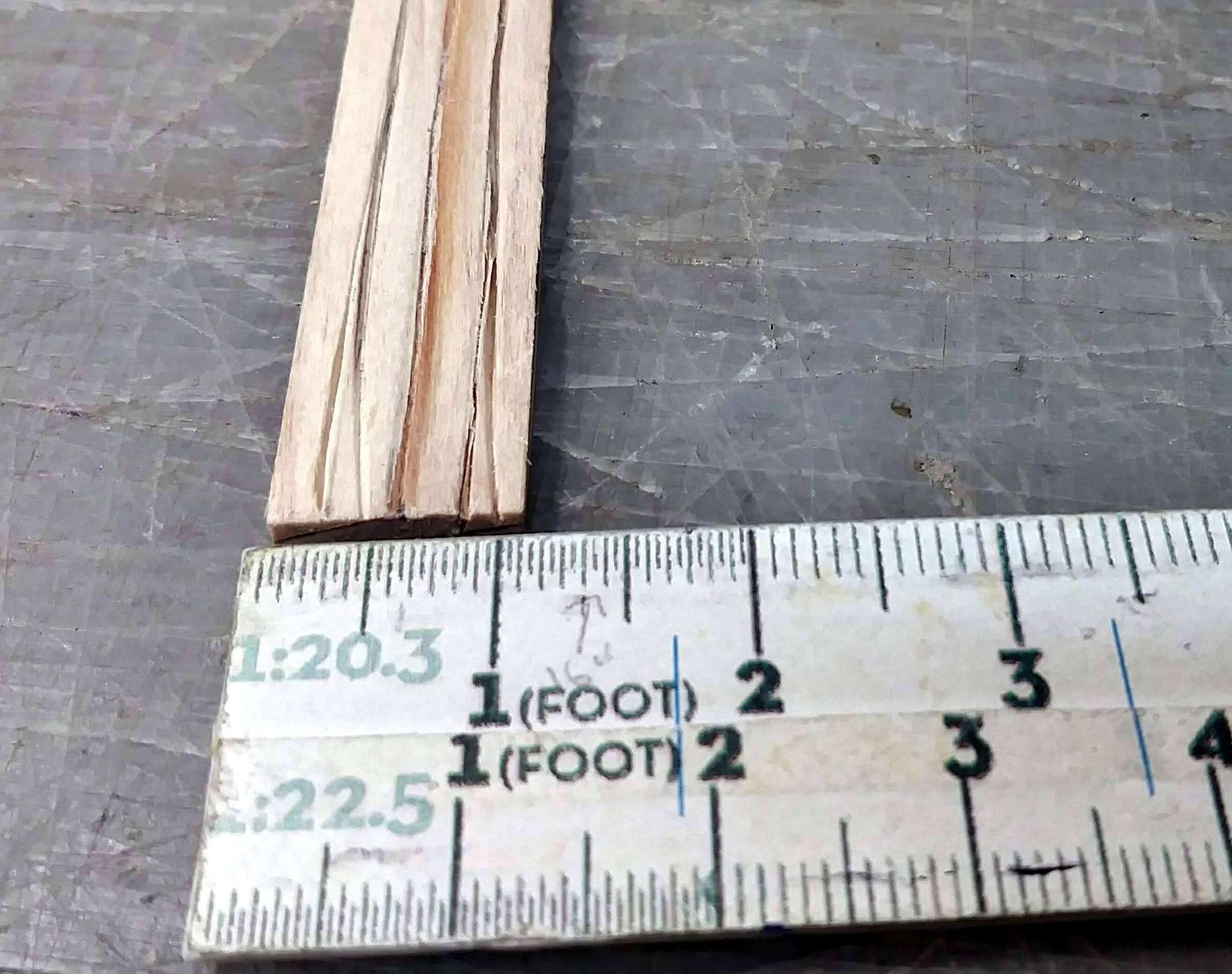
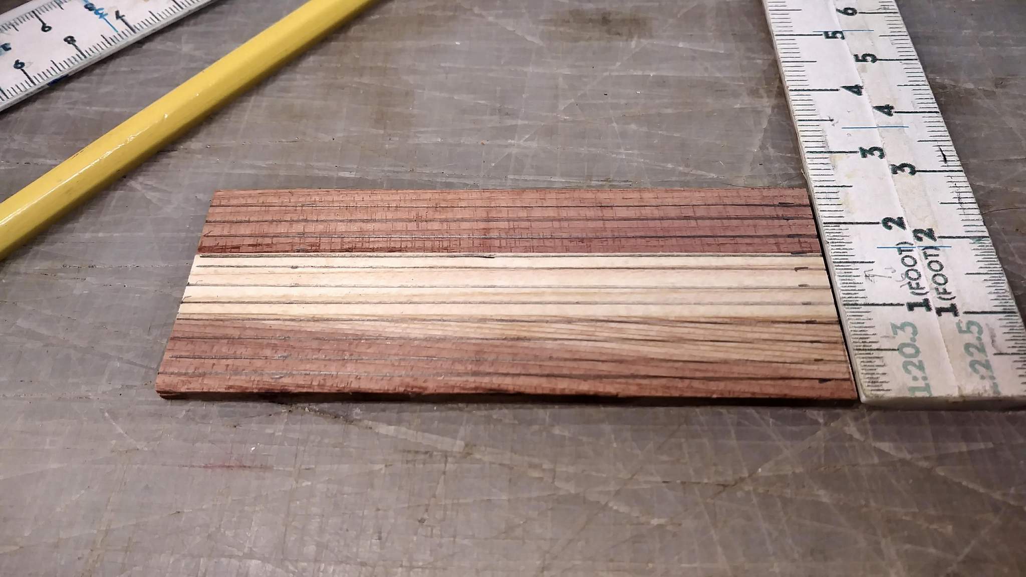
From even just a foot away, the door looks fine. The fact that the lines aren’t really V groves would require a magnifying glass (or a high-res close up) to determine. The lines are on .125" centers. That whole door is only 1.5" wide.
Looks like an old school “OFFICE” door to me. Also depending on the softness of the material. A cheap ballpoint (bank) pen works for grooving.
Jon,
It would indeed be too big if done head on. But by tilting the blade to 45 and then dropping it down to dang near not touching I think it would hit with only the edge of a tooth. I can’t promise that I am thinking its possible. I’m gonna have to give it whirl. But at any rate it would still be a pain the rear because you would have to move the fence of the saw for every groove. that could get pretty tedious.
Way overthinking for our scale of “OUTDOOR” model railroading. Only been outside for about 15 yrs and still learning what works and what doesn’t.
Rather than move the fence, you create spacers for the distance between groves and put them between fence and work piece. Remove one after every pass to shift the work closer to the fence.
Today I did quite a bit of 1:1 woodworking. This is $800 worth of “STK” Cedar that I cut, chamfered and notched to make 5 10 foot posts with 40" arms…

STK stands for Sound Tight Knots. All the mill work was done using a 12" compound miter saw. For the notches I make lots of slices then break the pieces out and smooth the bottom by running side to side across the blade while moving the contact point across the work.
These posts will get white gloss enamel and #1 Cedar would put us way over budget. I’ll use Bondo to fix some cracks and a few issues before paint.
Yes Jon I have use that method also many times and I thought about that for this. But that would be a lot of thin strips of wood to get the lines close enough together to make it look good.
Like Bob and Rooster have pointed out this is way over thinking it. I still think scribing them overall is the best method.
A few baby steps last night. First I finished the door by adding a Z brace to the back. I think I spy a place where some wire loops and a pin will serve for hinges…
Then I got started on dirtying up the interior. Still using just crushed coal. I found a container of “coal dust” but it’s about salt crystal size with a little real dust. I need to hit the right wall again, but I like how the left and rear walls came out…
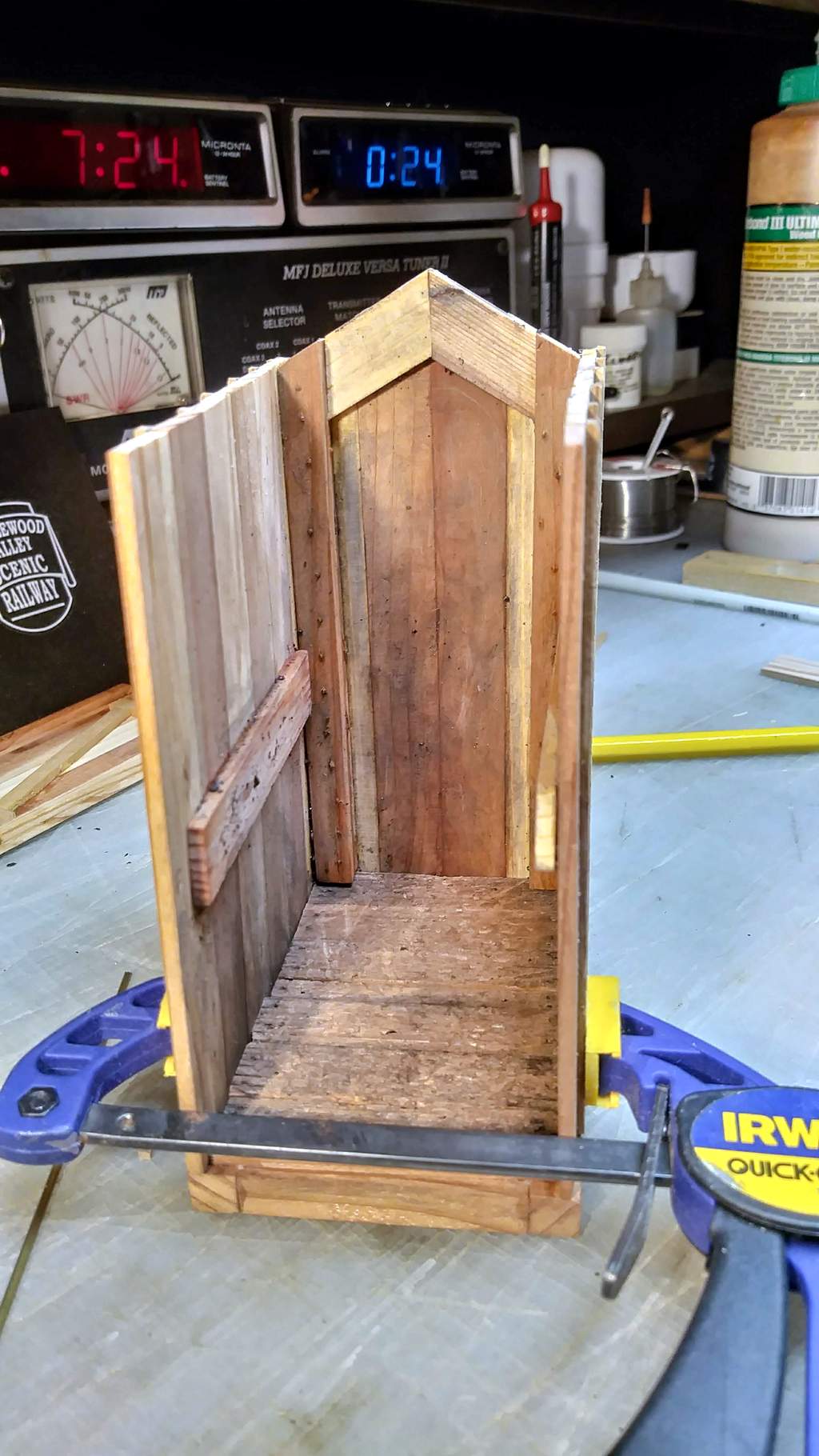
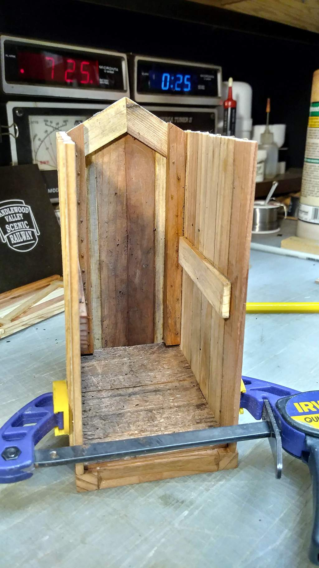
That ‘nailing board’ on the right wall needs lots of wear and dirt as it would be the first point of contact for a locomotive crew to rub against. I might have time to work on that tonight.
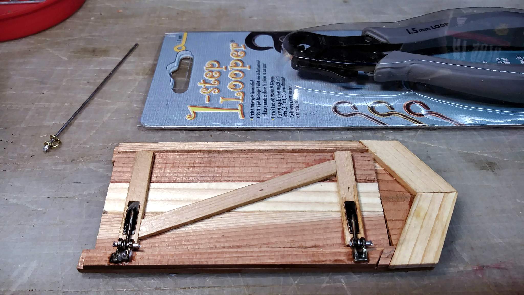
I need Marilyn to search for the jewelry loop making tools I bought after seeing Kevin Strong use them a few years back.
As always, you can see larger versions of the pictures by clicking on them - twice for full zoom.
1 Like
One of my goals for this year’s Mik was to use the unused / underutilized tools and supplies I’ve been collecting but never, if rarely used. It began with the mini table saw from Craig and the scale wood supply from Stan, both purchased several years ago. Today, I powered up the resistance soldering system I got from Bruce so long ago I can’t remember when! To help date it, the instructions are on VHS Tape and I had a player to watch them! I’ve never mastered using it, but it definitely did better than I could have done with a standard iron.
The project was to fabricate some hinges. The last few days I have been playing around with Looping Pliers I bought perhaps three years ago after Kevin showed how he used them in modeling. Another underutilized tool.
So here is the progress on the hinges so far…
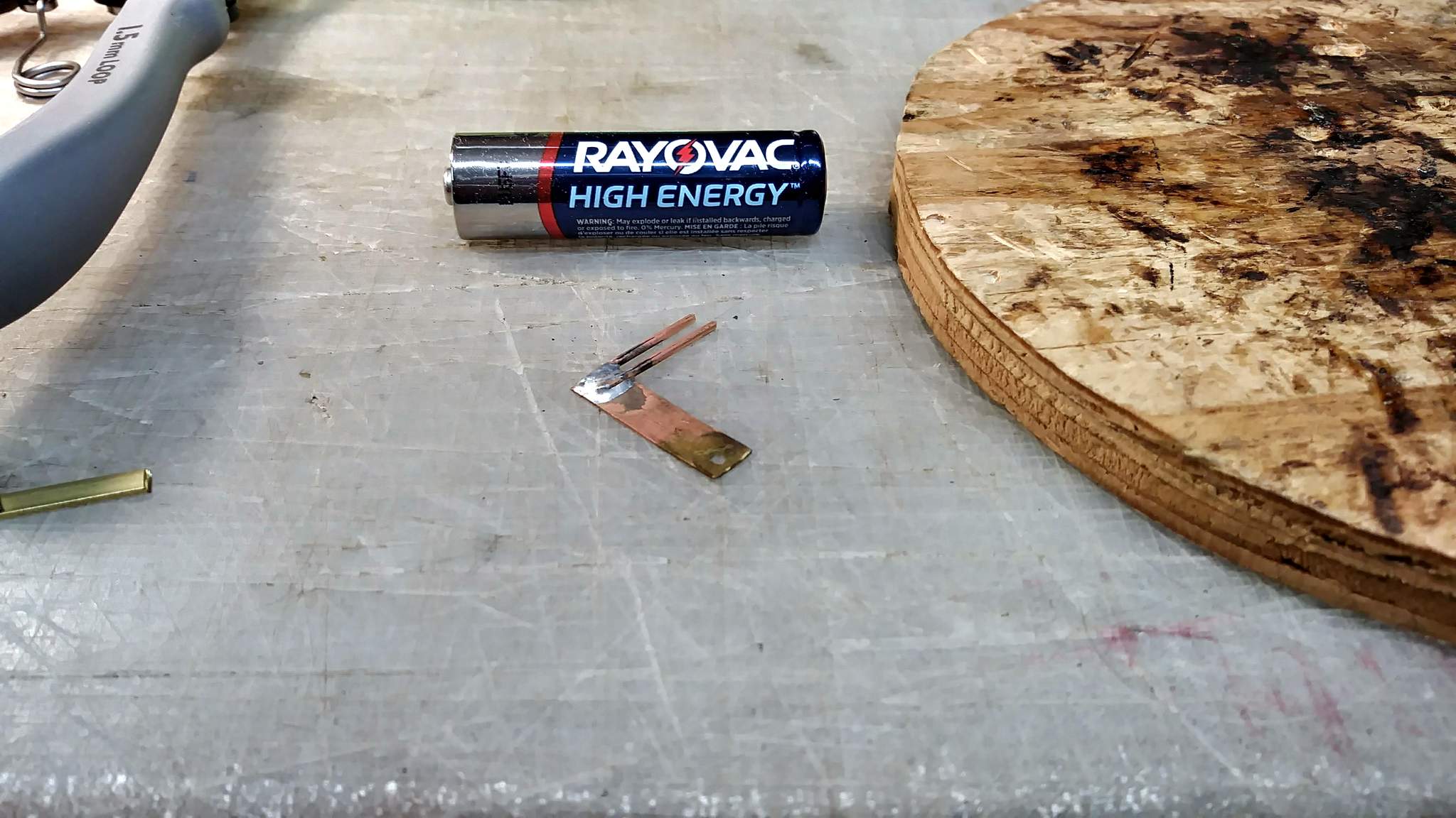
The AA battery is in the photos is for scale. Above, brass rod was attached one at a time. A little too much heat and a lot too much solder, but it worked. Next, use the looping pliers to bend some nice loops…
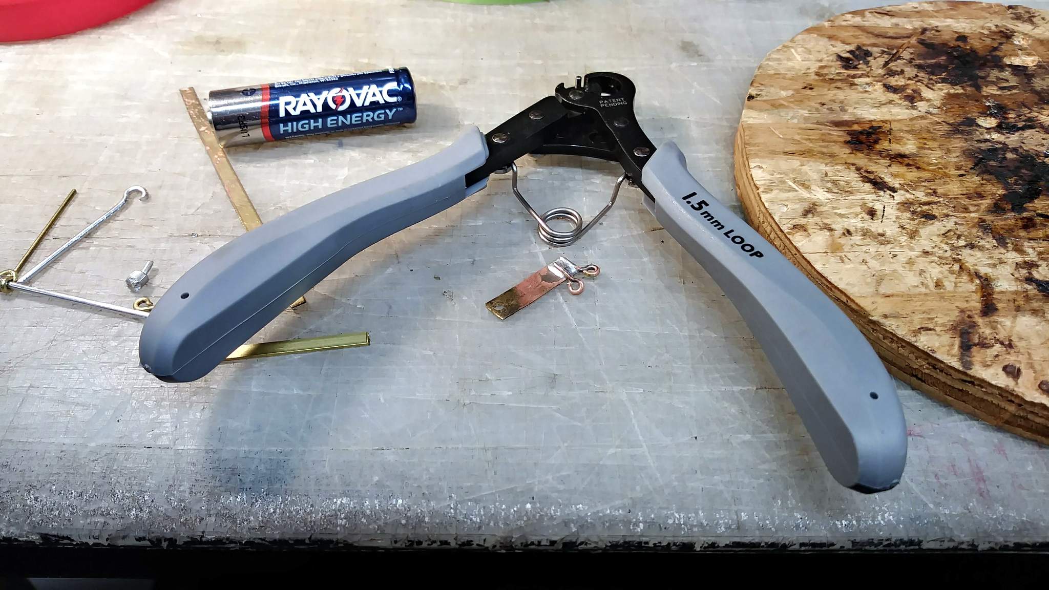
Next I spent some time with smooth jaw pliers tweaking the loops to line them up to allow a pin to pass between them. In between the two loops, another rod with a loop at the end creates the pivot…
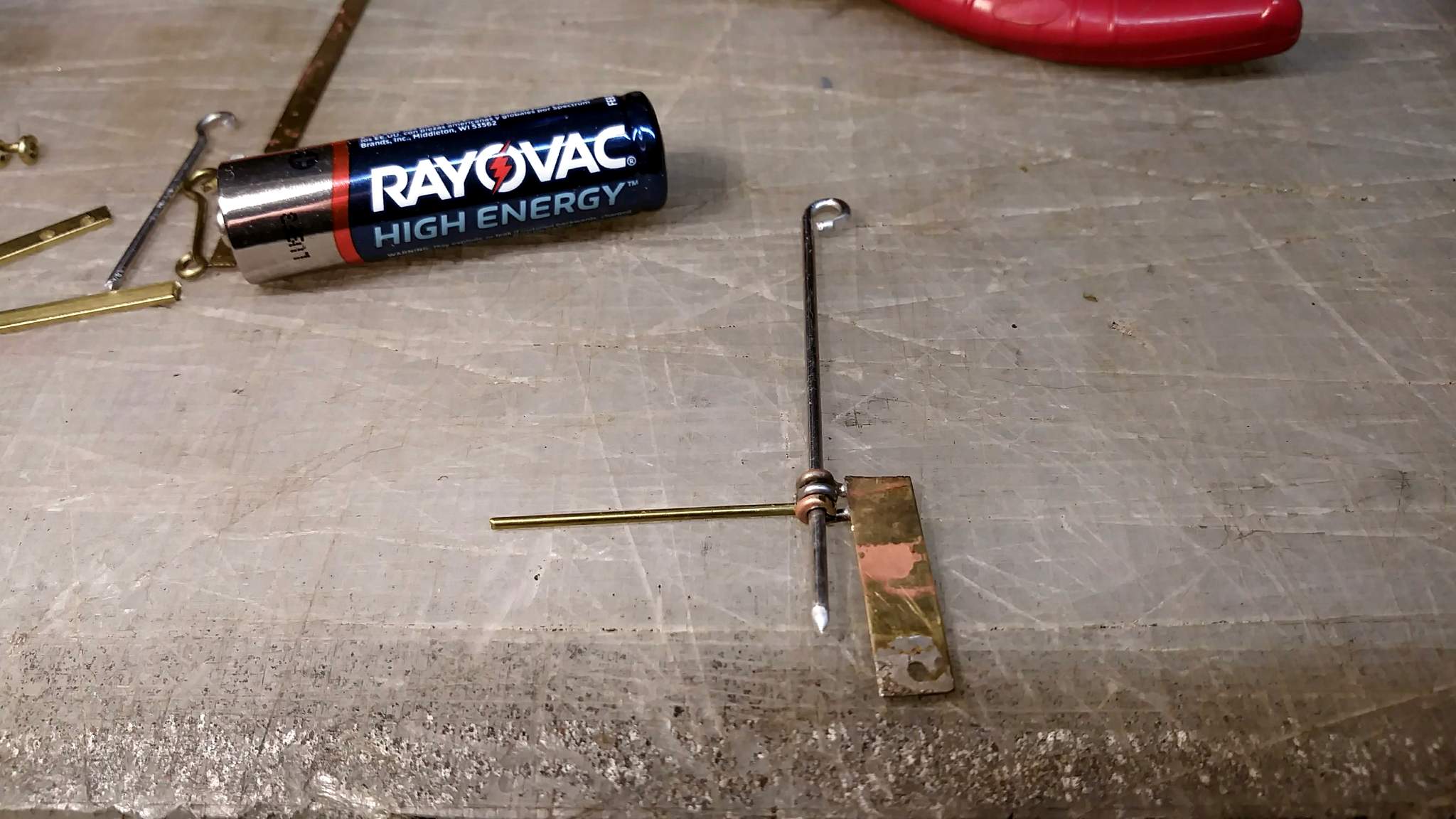
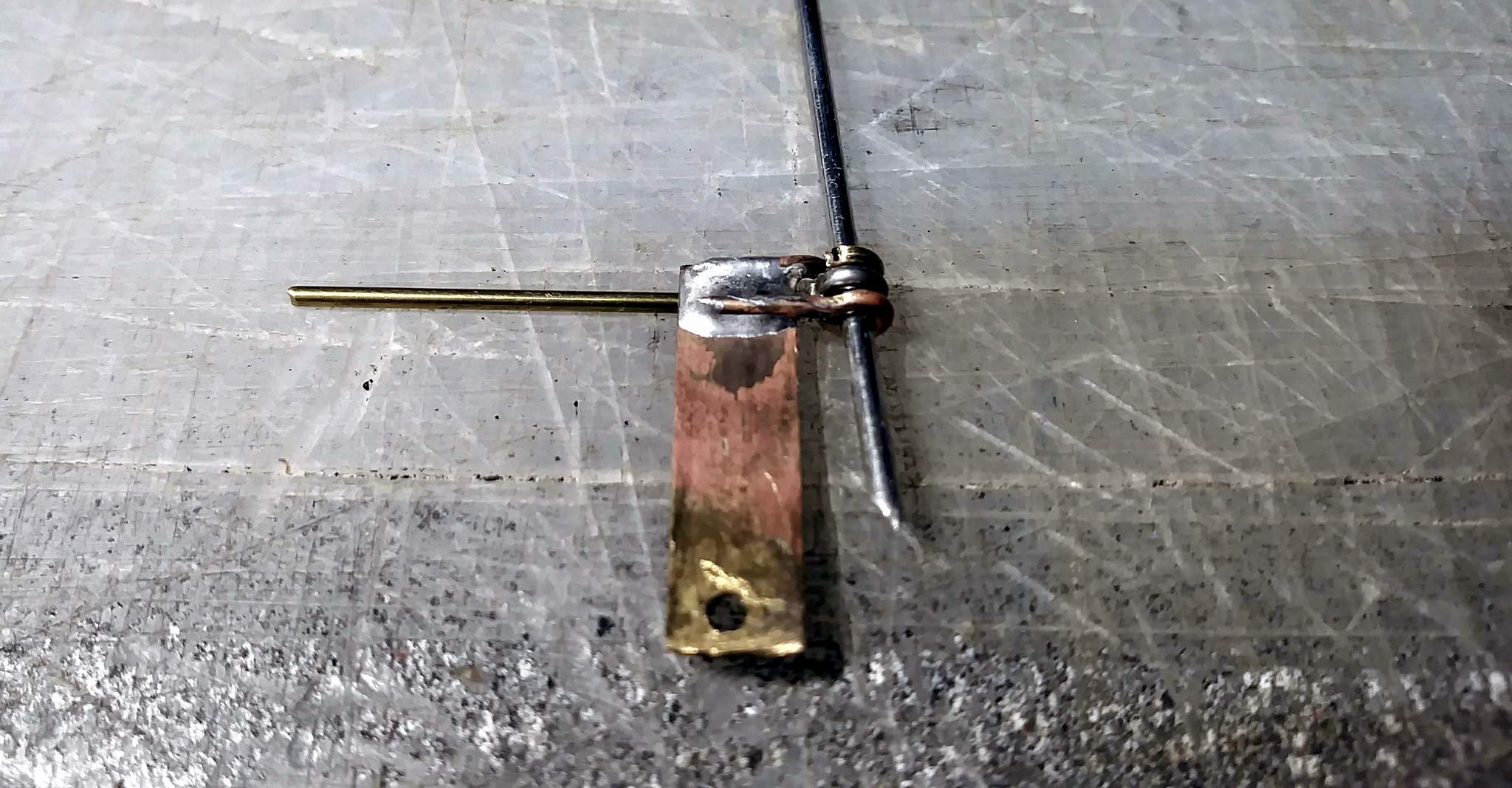
I’ll probably solder a strap under the pivot rod, then cut down the soldered piece to the height of the loops. There will be no attachment hardware, I’ll use a hybrid adhesive to attach the brass to the wood. Here it is flipped over…
I need to get the door done and move on to the roof this weekend so I have time to paint before the deadline. No decision has been made yet, but I have an idea for a removable roof.
2 Likes
Resistance soldering is a definitely a learned skill. I found that having a foot petal switch was 100% necessary. My issue is I keep getting my tweezer tips dirty and have to clean them with sandpaper, or cut some new ones. I’d really like to try a probe and clip setup or a probe and a flat plate set up. But it’s so nice once you figure it out.
I do have a foot switch. Absolutely necessary! These were done with clip and probe, but the clip was in a bad spot circuit wise. A ground plate would be really nice. I have lots of small scraps of .125 Aluminum sheet squirreled away at work. I wonder if I could just add a bolt for the clip and use that.
I’ve not had good luck with the tweezers, but they seem to be best to keep heat local.
My best results so far was soldering a brass plate over a modified brass hose adapter to make a plug for my drinking water hose on the RV.
1 Like
The hinges came out OK. Alignment of the pivot point is not perfect so the door won’t close all the way. That’s OK because the plan all along was for the door to be ajar. I’d like to round one end of the pin, but stuff is to fragile to stress it. I already ripped out one solder joint and my glue of choice, a hybrid CA/Acrylic Epoxy does not bond well to wood so any force will break the glue joints. Don’t ask how I know that 
So here they are, installed and working as good as they are going to get…
The item at top left above was my proof of concept.
.
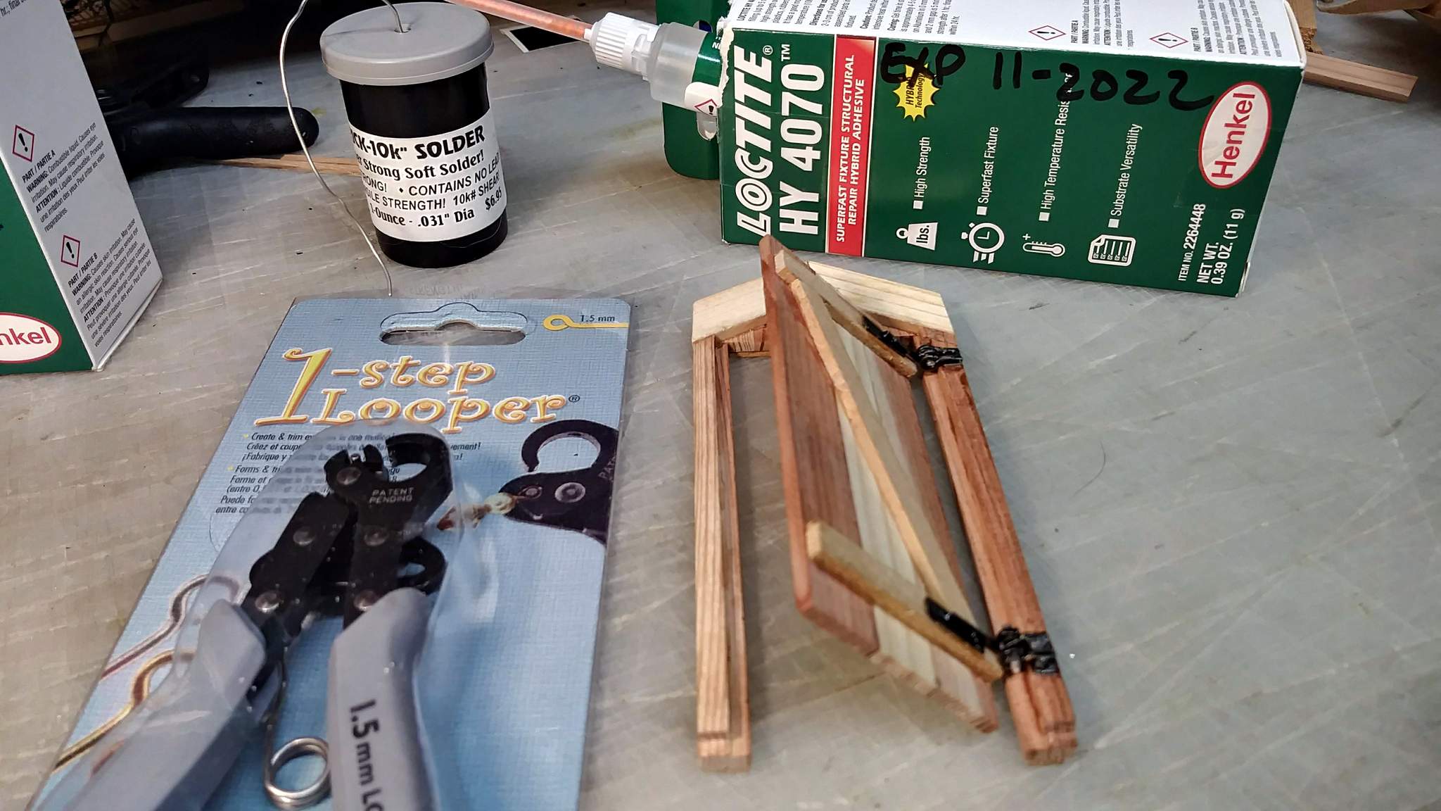
I really like the Loctite HY4070 for most things, but I’ll not use it on wood again. I wanted quick dry, and that it does.
.
Weathering the door interior, insulators and door hardware next. After that I can attach all this to the base, finish the battens, build the roof and weather the exterior. All in just over a week. I think I can do it!
2 Likes
Well, Is it done yet???
1 Like
Well done, Jon. The hinges look great.
1 Like
Hinges are awesome. One of my favorite things to make is working hardware. And you did a right fine job
1 Like