Large Scale Central

Big changes at Staver Locomotive for Spring Steamup

It is a old post i am aware of that, but how i am going to show pictures of what i achieved thanks to this post?

Cous thanks to this thread i am building my own now, a bit on there way and more production wise on my way!..It is looking really good!

To bad it is in the wrong section and they did not show more…

I would like to post some pictures of what i have done.

Thanks for reading Igor

justme igor said:

Nice.

You could start your own thread( https://www.largescalecentral.com/forums/13/track-and-trestles) / or an article ( https://www.largescalecentral.com/articles) to show your progress.

Hi Igor:

I’m glad I could inspire you to build some track using some of our methods…it looks great. I’ve been meaning to post pictures of the completed freight yard and some other things we’ve built.

Unfortunately, my father became ill with cancer two years ago and we’ve been spending a week each month helping my sisters take care of him, he is now entered hospice in his home and cannot be alone anymore, and hospice care only includes three visits a week. More unfortunately, I had to make an emergency drive to the Sacramento delta to care for him, as now both of my sisters are under evacuation orders. My older sister for the SCU fire in the eastern foothills of San Jose, and my younger from her home in Felton, Ca. near Santa Cruz. She lives high up in second growth Redwoods two doors down from our family home in the 1970’s. The fire line is now one mile west of her home, and we are all scared. I am also frightened for the Roaring Camp Logging Railroad only a mile to the East (one of the reasons for my obsession with steam was listening to the Shay’s climbing the grade each weekend as well as riding them many times).

The Swanton Pacific Railroad has already burned and there are horrible photos of the locomotives covered in ash and buried in burned debri.

Sad picture

Sorry for the bad news post…sooner or later I will post more photos to complete the thread. I don’t have them here at my dads though, so it will have to wait a little longer.

We haven’t worked at Stavers since December, however, Larry called the other day and a few projects are possibly in the works and some modest movement on the outdoor railroads property prep has begun.

Welcome to the board, and keep up the great work Igor.

Thanks

Karl

Nice switch building in the second pic Igor. It would be nice to see some close ups of that track work. (https://www.largescalecentral.com/externals/tinymce/plugins/emoticons/img/smiley-cool.gif)

@ gearhead,

Sorry to hear about all that bad news, i wish you all the best.

I lost my old man 3 years ago, still not over it plus a lot of “life events” afterwards…you will survive.

Be very careful and take good care of them AND your own health.

You sure was a big inspiration, many thanks.

Basically i adopted the idea and run a production process in my capability’s.

I make use of several jigs

The making of ties I think i figured out a quicker way and i am going to use different wood: Azobe.

Fir is nice and will last very long(i read one post somewhere: 19!years!)

Stay save

@ David,

I must still clean it a bit, I used to much putty…But i am still in the “experimental” phase.

I used different kind of woods, big mistake! those ones will be placed outside of the view, and will use azobe from now on, no wood stain.

The 3 way switches where intend for inside use, but i dont like that wood, probably i will rebuild them.

The frogs are made of foam pvc, the next once are going to be made from hard solid pvc sheet.(hammer proof stuff)

Ps i dont wanted to hijack this treat.

Hi Igor:

Thanks for the best wishes, I’ll put them in my wallet and use them as needed. These are tough times for literally millions of people if not more, and we’re just trying to navigate our small part in the madness. We had slightly good news on the weather helping the fire crews, however a few homes burned last night and we have no way of finding out whether my little sisters house was one of them or not. The news showed fire trucks driving in fire on a road walking distance from her home.

That said, I don’t want to turn this thread into a pitty party. After rereading it a couple times to get my head around everything I was doing then, I realized I had promised to provide details about a number of projects and I want to apologize for not following through…after the steamup was over, Larry had us take some time off, it was a very expensive winter at Staver Locomotive, and we were also worn out from all the long hours. However, I continued to document our progress, and I feel this thread should have a decent conclusion.

I found some pictures on my phone that would provide the ability to notch this thread forward a little before I have access to all my files back home. So I dug out an old WinXP computer from my dads back bedroom, that still has a copy of Photoshop from the old days, and spent the afternoon preparing them for posting. So tomorrow I will post an actual update to this thread.

I too, would like to see pictures of your process and see how you have accomplished your version of our track building methodology.

Thanks

Karl

Quick edit…initially, I didn’t see the close up pictures in your post. One of the pics I will post is of a 3D printed version of our frogs before we CNC machined them on the mill. I am really happy to have inspired someone to suffer as much as we do producing track this way(https://www.largescalecentral.com/externals/tinymce/plugins/emoticons/img/smiley-wink.gif)

Thank you Igor, That stepped set of switches caught my attention (https://www.largescalecentral.com/externals/tinymce/plugins/emoticons/img/smiley-cool.gif)

So I had to help family the last couple days, and wasn’t able to post. First thing is to make a correction, I realize that I said we use Fir strips for the ties…Jenn informs me that I was wrong, and we use Ceder for the ties. Larry buys tongue and groove Cedar for walls and we rip those into strips for the tie making machine.

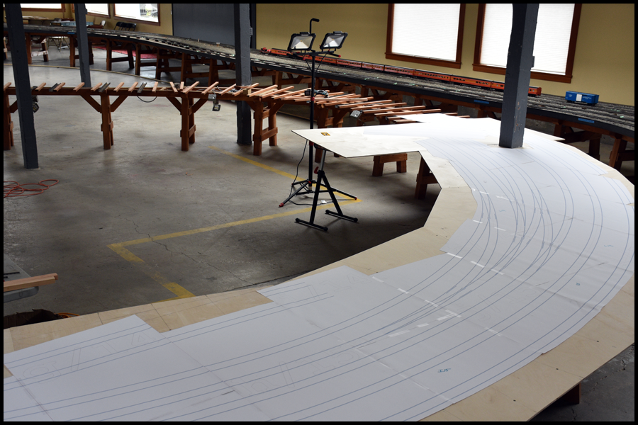
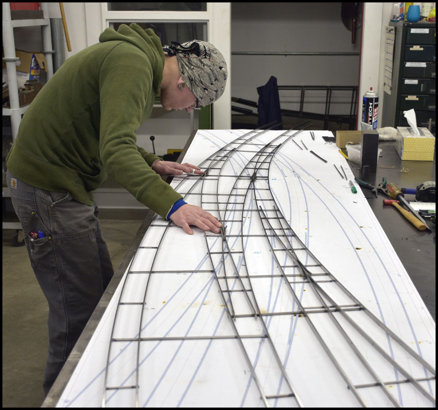
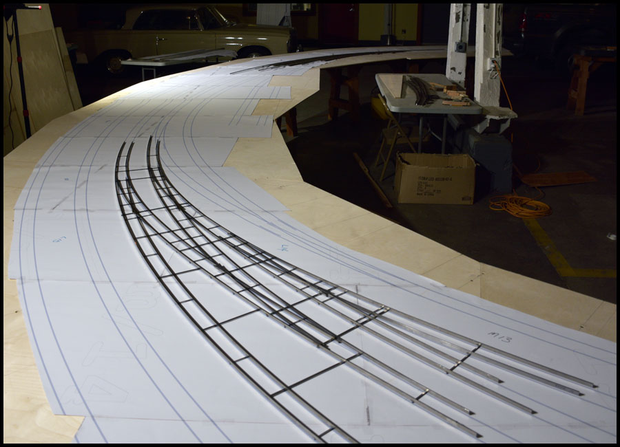
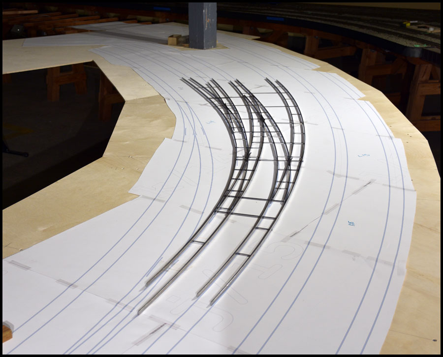
We’re leaving back to Portland tomorrow since my sister has evacuated to my dads. I have put together some pictures of the final building of the middle yard loop, but won’t have time to post for a couple days.

I mentioned in an earlier thread that we changed the way we make frogs during this project. The old method was manual and used jigs and keyway cutters, and only allowed for a few frogs, #5,7,10, and 14. As seen in the March 14, 2018 post in the fourth picture, I described cutting our old frogs down in length, and this got me thinking about a new method. We had already been thinking about making them using cnc, and I had laser cut some custom mill vise parallels to facilitate the process. However, by the nature of trying to fit all these curved turnouts in the allocated space, we were going to need many different angles of frogs, and each size would need its own parallels and fixtures.

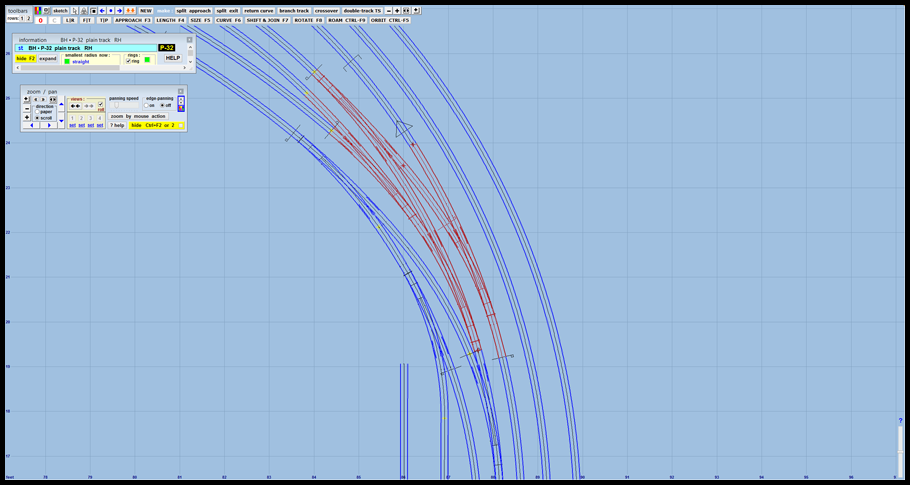
The new cut down design made Larry and I realize, that we could profile the frogs instead, reduce the number of operations to produce them, and allow for any angle to be produced. So Larry created a model in Solidworks of the frog using drawing relations, to allow the model to regenerate a frog simply by changing one dimension of the frog…the angle. In the mean time, I set about teaching myself the CAM system that comes with Solidworks nowadays, so we could generate cnc g-code. The beauty of this, is that if we design a turnout to fit a tight location, or an intricate turnout such as the tandems, we can create any frog needed, even if the angle was non standard such as 8.175 degrees or whatever, and the toolpaths and g-code would be automatically created and ready for production.

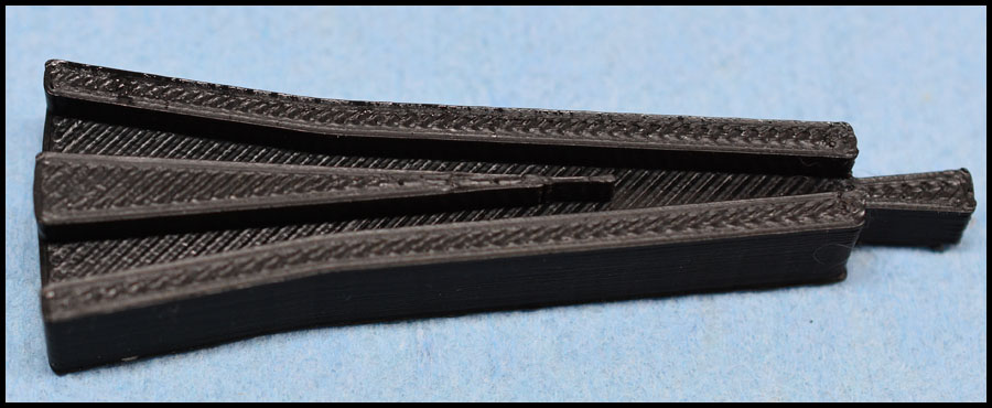
The first thing we did was 3D print a couple to prove out the concept…here is a picture of one I found on my phone.

3D frog

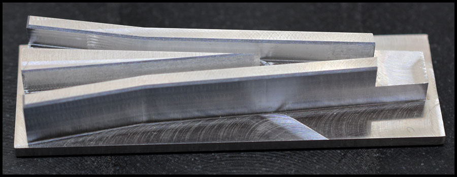
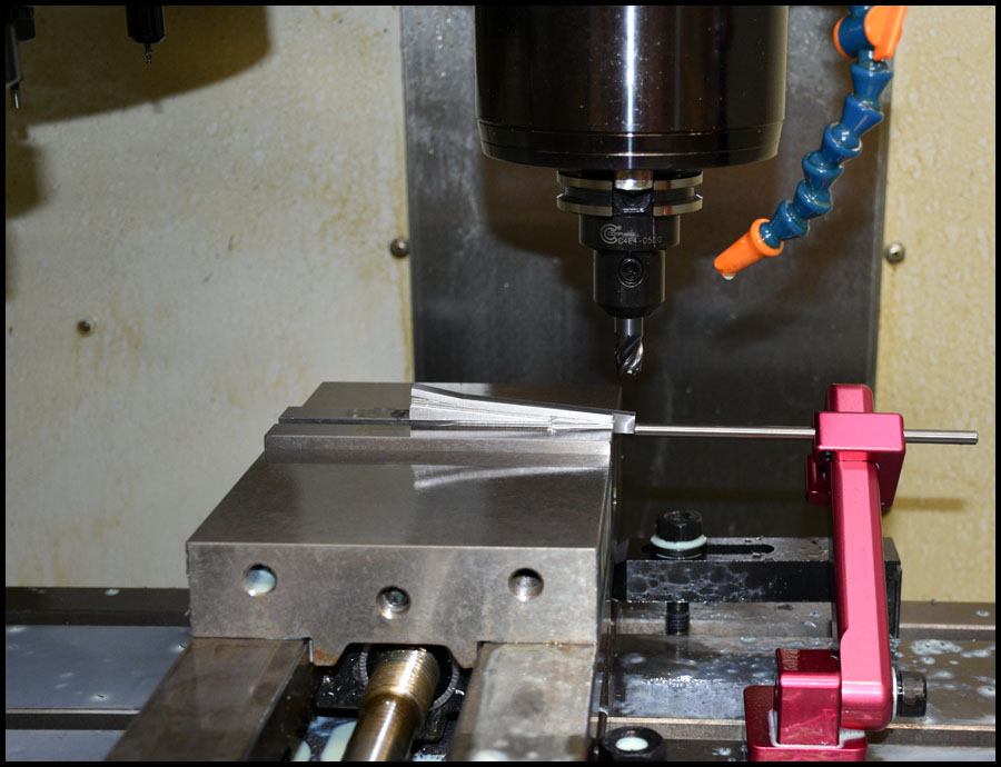
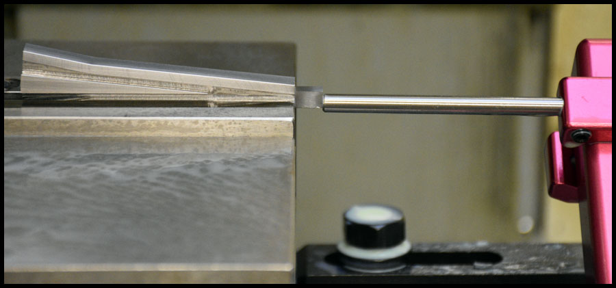
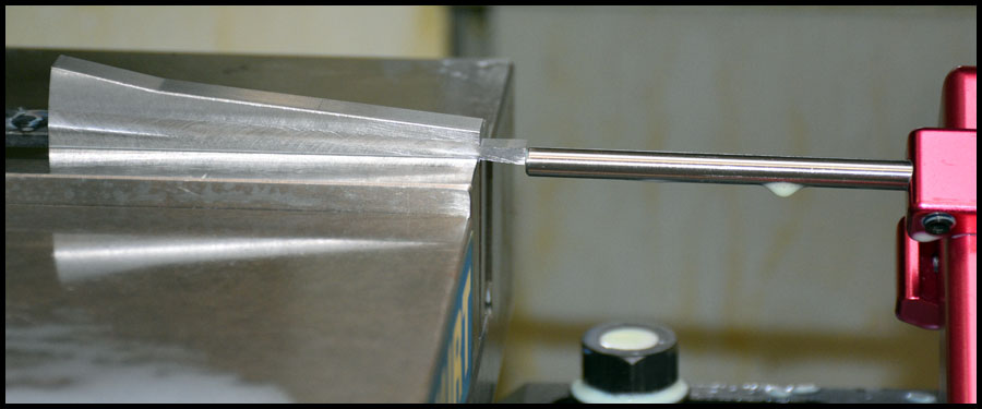
Next was to try it on the mill. We made the first couple out of aluminum to test our toolpath strategy and such. We can now make the frogs in only four operations instead of nine, and of course, the cnc is much faster than manual.

I found one picture on my phone of the first operation in aluminum…

Alumafrog

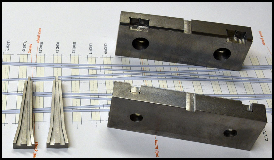
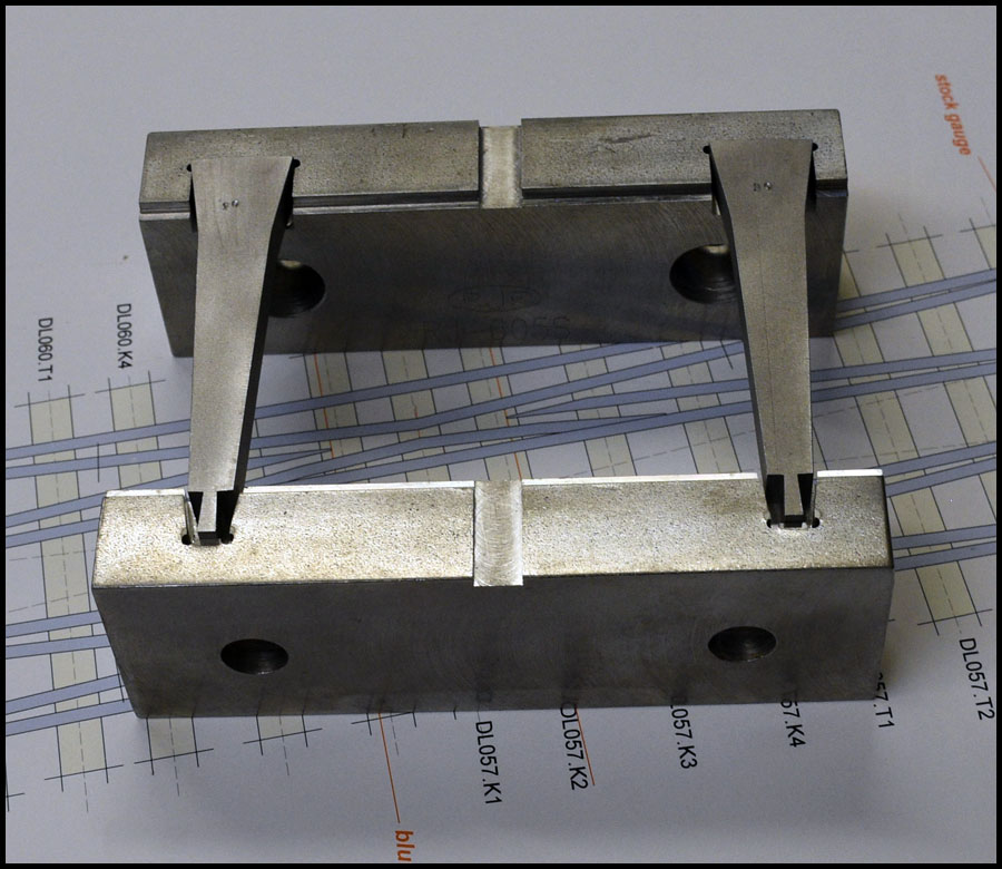
The second operation is to turn them upside down and mill the extra material off. Even though the angle of the frog creates a substantial difference in lengths between say #3 and #14 frogs, the dimensions at each end of the frog are consistent enough that I was able to mill a shape into a set of steel vise jaws that allow me to clamp two frogs at a time, spanning from one vise jaw to the other, and remove the excess material and set the thickness of the frog.

I don’t have any other pictures of these operations on this computer so I can’t provide much more detail until later, however, the third operation involves milling away the area where the rails get welded on the small end of the frog. This is two simple and fast operations that don’t take long at all.

Once we made some out of steel, and fine tuned speeds and feeds, I went ahead and created programs for #3 through #14 frogs and ran production runs of each size so now we have lots of frogs. If we need a special size, I can make them easily as needed.

One fly in the ointment, however, is that Larry got annoyed when Solidworks changed policy this year, and won’t let him have a copy on his laptop as well as the shop computer, so he cancelled it. So next time we need frogs, I have to redo everything in Fusion 360…oh well, just another learning curve. Fortunately, I have already learned to create models in Fusion, I just need to learn the CAM system.

That’s it until I’m settled back in at home in a couple days.

Happy steaming

Karl

Edited to correct some punctuation and missed capitalization of some names.

Hi all:

Just a quick note, I’ve been scouring my hard drives for all the pictures I took two years ago and moving them to folders so I can edit them for posts. Since I got home from Ca., I have had many irons in the fire trying to get caught up with life…good news is my sister has been able to return home to her smokey smelling home…but it is still there, and so is the Roaring Camp Railroad.

Tomorrow, we meet with Larry at Staver Locomotive to discuss some projects on the railroad, so we may be building again soon…we hope.

Anyway, I will post pictures and descriptions and try to complete this thread soon, so at least there is a conclusion for people who find it in the future, and it acts as a complete story.

Thanks,

Karl

AKA Gearhead

Hello:

We’re back working at Stavers for now. We met with a group of designers yesterday who will design the gardens and various features Larry wants to add to the property. They seem really excited to tackle the job. Now Larry is under pressure to get the outdoor track plan finalized so they can design around it. Much more than just the railroad must be considered so it can be used as an event space and be legal, however, they can’t really design it if they don’t know where the railroad will be…last year I designed about 15 or so track plans based on criteria Larry put forth, but as I’ve said before, things change a lot at Stavers, and many people have been getting Larry’s ear, so I have only a rough idea what will happen…many want there own idea of a railroad built by Larry for them, so we will see how it plays out…ultimately, its Larry’s decision. Right now, we are not building any new track, instead, we are cleaning the shops and reorganizing things, such as moving the laser into the machine shop, that means moving the cnc mill and making room for the Laser, plumbing, and exhaust venting out of the building.

Two of Larry sons are going to be helping construct the outdoor landscaping and had some great input during the meeting. Anyway, that is just a quick update for those who care that at least some forward progression is occurring on projects at Staver Locomotive, and I may not have to get a regular job as seemed might be necessary.

Working today and tomorrow, but should have time to post more pictures this weekend.

Thanks,

Karl

AKA Gearhead

Edit for errant comma and a finger slip spelling

Gearhead,

Great! Our clan drifted through Staver last year during the RSGRS open house event. The crew there was incredibly hospitable, allowing my young boys inside the loop to see how to bring a real steam engine to life. I cannot imagine what you’ll be able to accomplish in that outdoor space!

Aloha,

Eric

Karl

Do you have a link for this up and coming wonderland ( were is Stavers located etc .)

Sean McGillicuddy said:

Karl

Do you have a link for this up and coming wonderland ( were is Stavers located etc .)

Google is your friend: http://staverlocomotive.com/

Hi Sean and everyone:

These 4 pages in this post are the only thorough description of the what and how of Staver Locomotive. The website sucks, and why is a story of its own. This is one of the reasons I have been writing this on my own time, with the hope that someday the website will be rebuilt and some of these musings and photos might be made a part of it.

Here is a link to the camera page at Stavers.

Live at Stavers

…there are various cameras around the shop, but they often get pointed at “scenes” instead of the overall railroad. The cameras and maintaining them aren’t my responsibility most of the time, so I can’t do much about how they are used. However, there is a small steamup this Tuesday Sept. 4, Friday Sept. 11th, 2020 for local guys, and I will make sure that the cameras are pointed in ways more applicable to seeing some action on the railroad. Steamups like this are usually 10am or so till about 4pm PST.

Here is a link to a well done video that shows very much the flavor of one of our large steamups. This video was after we finished the work I have been writing about in these pages, so you can see the completed track work. The outdoor railroad and dam have been demolished since, and I will post some pictures of how it all looks now over the weekend.

Staver spring steamup 2019 by TrainDave

Must go to work now and finish preparing the Laser move and repair a shredded feed drive belt in one of Larry’s Monarch lathes.

Happy steaming

Karl

Here’s the video from TrainDave via Gearhead:

Hi all:

Ended up with many things to do at Stavers, so I am working all weekend and the holiday…although today I’m mostly laser cutting some stuff for myself. I have to finish some projects today or I won’t get the chance for a couple weeks. We moved the CNC mill to its new location yesterday and got it leveled and up and running again. The laser will be disconnected and moved this week, then it will take about a week to reinstall it in the machine shop…much more involved move than the mill. We have to cut holes and place a vent in the outside wall, run a new 50amp 3ph circuit, drill into the floor for the exhaust support assembly, plumb new air and coolant lines, etc. I did however, bring in my best buddy to help, he is very talented, and his skills compliment mine, so it should turn out a very professional installation.

Here is a picture of Larry’s mill, just about the same size and capabilities of my own Kira high speed drill/tap center. In the vise is the first operation, profiling a steel blank into a frog so it is like the aluminum one in the earlier post.

HAAS super mini mill

Yesterday we turned it 90 degrees CCW and shifted its position some, which will give just enough room for the 500w laser, chiller, air dryer, and exhaust fan assemblies to be moved into the corner behind it, and finally get it out of Larry’s office.

Here is a couple pictures of the second op…sort of, couldn’t find a picture of when it was in the mill. I think I only took videos, but I don’t have time to deal with those right now. I shot these photos the other night while Jenn and I were cleaning the shop and doing maintenance on the lathes. The frogs have the 2nd, 3rd, and 4th ops done because I don’t bother making any and not finishing them, so you will have to imagine the frog would be the same shape as the aluminum one above, and that it would be inserted into the vise jaws upside down. The slot in the middle allows me to use a square shaft to align the jaws as I bolt the jaws into the vise.

Frogs out of jaws

You can see in the next picture how these #10 frogs are placed, the front and rear corners are always the same dimension, so I can grip any size frogs and mill the excess material away.

Frogs in jaws

Here is a frog prepared for the 3rd operation, I use a straight edge in one of the rail slots to locate the frog in the correct position. This op takes about forty seconds from start to finish, including loading and unloading.

Start of 3rd op

3rd op finished.

3rd op

4th op is basically the same, just flip the frog over and use the straight edge from the back side.

4th done

And that’s how we make frogs now, in large quantities, in 1/10th the time…so we can keep Jenn busy, working her magic, welding turnouts together.

And finally, a teaser of the rest of the story of the build out of the curved yard. My next post will start describing the process of how we built up the yard, including a network of seven curved and interconnected turnouts. This is the start of the yard, and it begins by testing the placement of the first Tandem turnout for positional accuracy.

Tandem placement test

I must head to Stavers now, and will try to post again tomorrow…but as usual, I am a very busy guy.

Hope I’m keeping it interesting.

Thanks

Karl

AKA Gearhead

Hello again:

First I wanted to note the correction from a couple posts up, I was wrong about the date of the next steamup, it is this Friday, Sept., 11th from about 10am-4pm PST. Also, last year we had a power supply blow up on the machine shop computer, the new installation of Templot2 has no longer has reference locations for background image files that we use during track design and construction. I looked for them the other day, and I know I have them, but wasn’t able to find them at the time. Unfortunately, this means I have to use a different technique to explain my next part of the story that will not be my first choice…oh well.

As explained a couple pages back, once we had placed the diamond crossover on the road from outside, and then built and connected the yard throat interchange, based on templates created in Templot, we would now have track that was built as exact as we could, located on the railroad and also represented in the computer. The next problem in designing the new yard would be ensure we don’t run into one of the two 4x4 ceiling posts in the yard area, as well as ensuring that the beginning of the yard would align with the track that needs to bridge the entrance for for people to enter the area. My solution was to pull taught string lines from the main building support structures and carefully measure the locations of not only all the posts and obstacles, but the frog positions of the turnouts already built and placed. I used these dimensions to create a DXF file of all the posts and points I needed the track to pass through to clear them, then imported the file as a background image, and used the measuring tools in Templot to to place the already created Templot yard throat and diamond crossover relative to the the obstacles. This effectively gave me a precise location of our track relative to the entire building that I could use to design the yard.

This screen shot of Templot unfortunately, does not include the DXF for the reasons stated above, so I used Photoshop to add some circles to explain what I mean. In the picture, the red circles represent the two 4x4 posts and the yard entrance, the yellow circles are the frog locations of track already built, installed and used to align the DXF file. The black circle is the locations of two frogs that when measured after completion of the yard, were within one half inch of our Templot measurement of the two frogs relative location. I am very happy with that result, especially when you consider the two bridge crossings, and the fact that we super elevated the entire two track mainline loop to 3.5 degrees after completion. Also, we cleared the 4x4 posts at the desired spacing.

Circles on image

We also experimented with scaling a satellite photo of the building and placing the track plan over it to visualize the outdoor railroad. We went farther designing the outdoor track than this next picture shows, but it is useless now as the decision was made to tear out the outside loop, fill in the pond and level the area, and start designing with a clean slate. I have also completed adding much more of the existing railroad to our Templot track plan using the methods outlined above to find the locations of the frogs in the existing railroad. However, these photos were the ones on my home computer as I write this, so that is what you get…

Satellite overview

I’m going to take a break for lunch, then I will post some more yard pictures and build story before heading to Stavers again.

Thanks

Karl

Back again:

So after finishing our first Tandem turnout, we had many more turnouts to build very quickly since we were running out of time before the steamup. By this point in the build, we had mostly finished re-sheeting the yard to make it wider, but now we had to print out the entire yard on heavy gage (46#) paper and lay it out. I printed all of the 2’x2’ squares, and Jenn tediously trimmed all the edges down to the alignment marks. We then taped all the squares together from both sides until the entire yard, from bridge to bridge was one giant sheet of paper. At first, it looked like I must have made a terrible mistake, it just didn’t look like it was going to fit…but it turns out, that just a tiny misalignment at one end, leads to what looks like insurmountable error at the other, just one little wrinkle can make it align terribly. However, we kept adjusting using our previous alignment marks from our test fit of the mainline curve, and slowly, we got the hang of shifting the paper by creating small wrinkles at the alignment points, then working the wrinkles out towards the ends of the loop…low and behold, it ended up fitting perfect.

I couldn’t find a picture of the entire template laid out without the yard built up over it, this one is when we had about a third of them taped together, and it looked like it would fit well and my confidence was high everything would work out for the steamup. Joe would build super structure during the day, then Jenn and I would add the plywood top in the evening. We had to keep building turnouts so I must’ve neglected to get a good overall picture. So my last paragraph would have described what we were going through a few days later than this picture. At this time, we were building this curved network of turnouts.

Templates on table

Our welding table at the time was not big enough to build all seven, so we started by building these four first.

Templot quad vurves

As usual, the inverted printout of the template were used to build the turnouts…here is Jenn inspecting her work.

Jenn inspecting quad turnouts

Test fitting in place on the railroad.

Test fit in place

Another view

And of course, Jenn had to make ties as well…

Tie shot

While building these turnouts we found out two things about our welding table, it wasn’t big enough, and it had a bad warp where someone used a rosebud or acetylene torch to heat something up in the past. It was only 1/4" thick and wasn’t built with precision flatness in the first place and did not have leveling feet either. We knew about the warp and had always been able to work around it…not so in this case, so it was a pain to build, although the end results were wonderful.

After the steamup, we bought a larger 1/2" thick 900# plate, modified and strengthened the table frame and added adjustable leveling feet, then using very thin tapered shims I milled, placed, welded, and shimmed, until we were within .010" across the entire surface. I don’t think it could be better without having the plate surface ground. It’s an excellent surface to work on now, and the added mass just makes the table much more stable.

Got to go to Stavers.

Thanks

Karl