Large Scale Central

Big changes at Staver Locomotive for Spring Steamup

Hi Rob:

Good to hear from you, sorry it took so long to post again, the cold really got bad and I had substantial pain in my teeth from sinus pressure. It finally began subsiding
Thursday night…

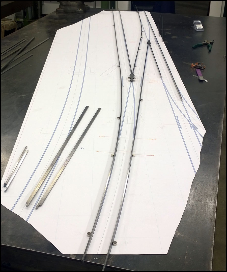
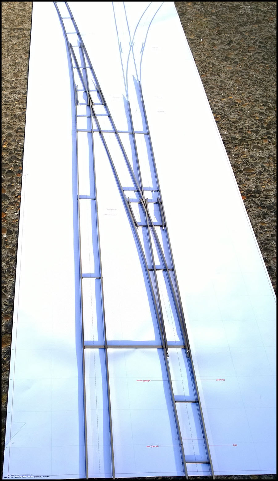
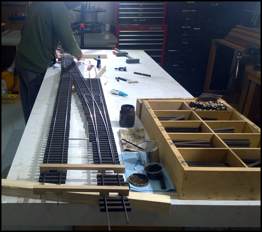
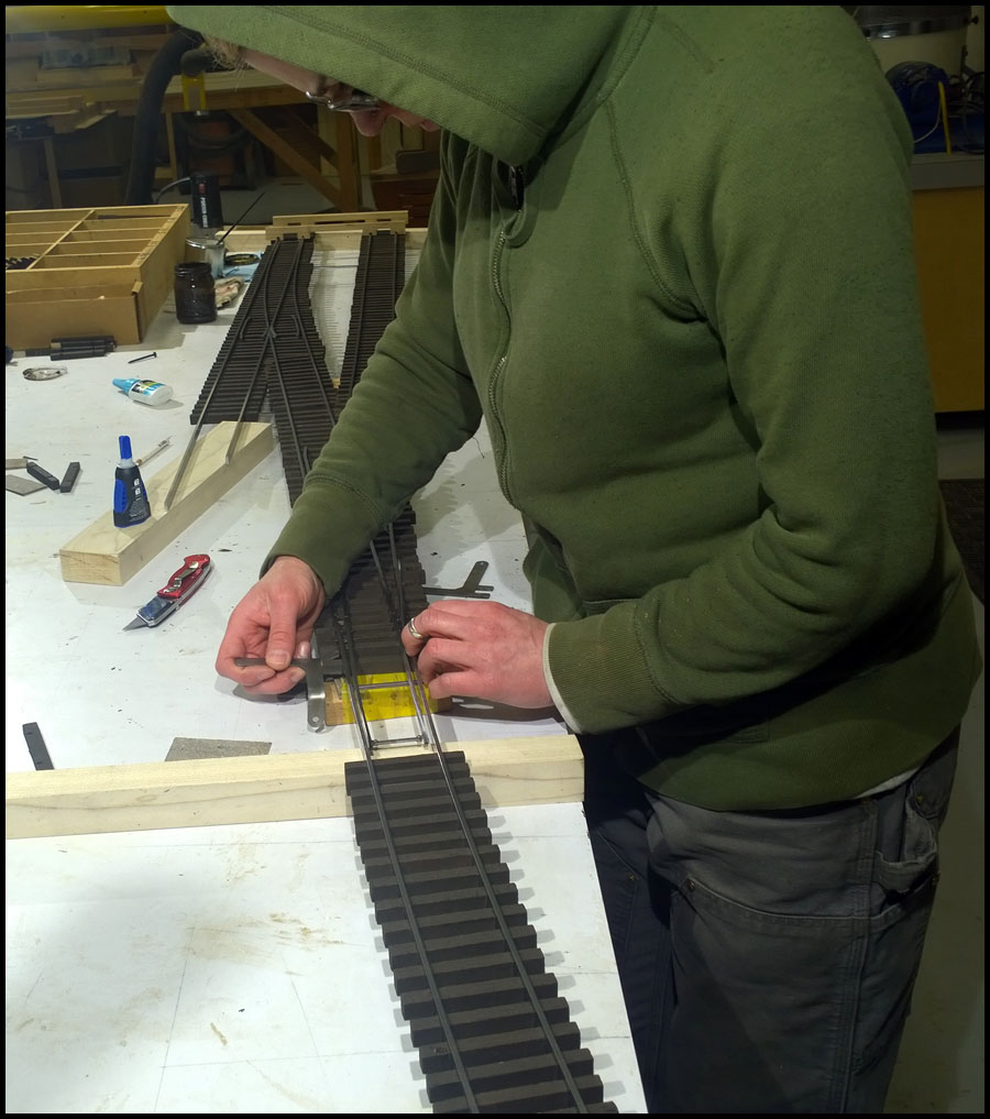
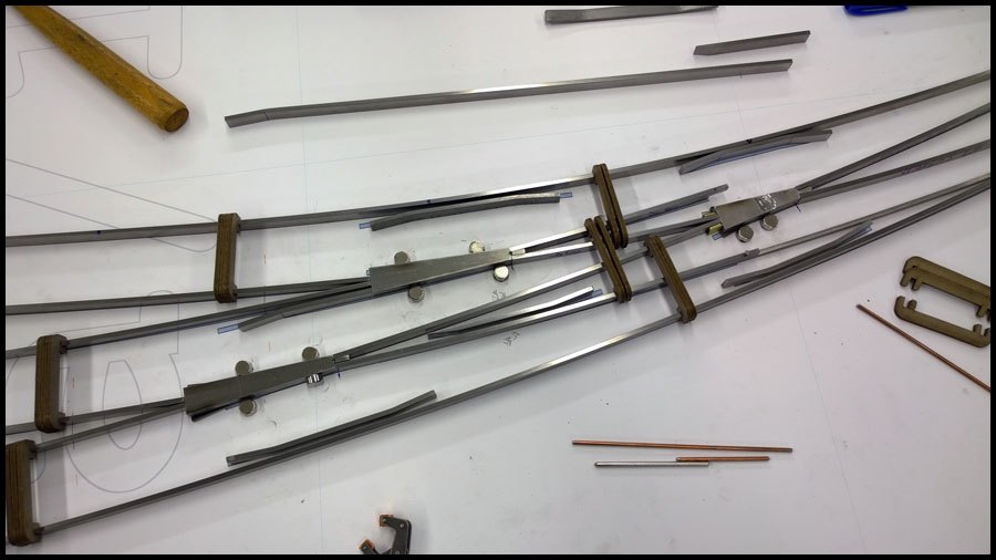
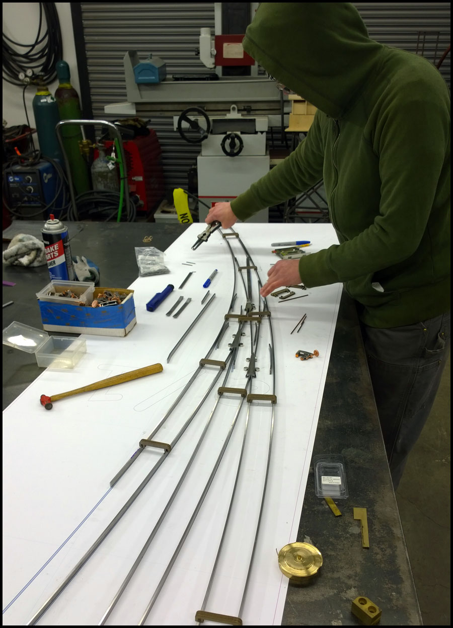
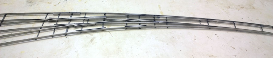
Also, the curved single sided tandem turnout we’re building this week was tougher than I thought it would be. Turned out great in the long run, but definitely had a
learning curve. We have to build one more, but now I know how so it should go much smoother.

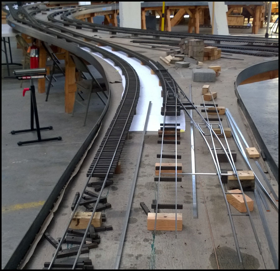
The outdoor loop is remaining single track as plans are now, however, there will be extensive passing, staging, and storage tracks on the outdoor railroad extension. There is
also plenty of time for plans to change.

I appreciate the offer of the camera body, and that is a pretty nice camera from its era, but it is also about the same as the one I just had fail on me, after 12 years or so
it is time to upgrade. I have been saving my carburetor and distributor money for a while and have enough to get a nice semi pro or pro camera with lens package. My
problem is just time.

With April starting tomorrow, there is still a lot to do around the railroad. So my posts might get shorter or have a little less exposition.

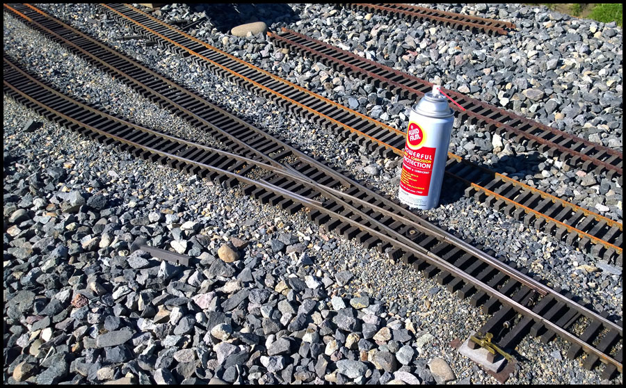
This post will be to catch up on some pictures I’ve taken related to things in other posts. First is a report on the rust and corrosion preventative Fluid Film.

In the picture is the turnout with the Fluid Film sprayed on it twice during November. After sitting all winter, I walked up and it looked like some surface rust had
formed, but not too much. I figured a scouring pad would make it nice, however, I just wiped it with a rag, and it looked great.

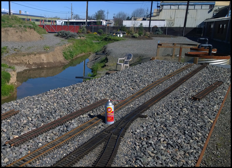
I purchased this can to test the product. It is available in larger bottles and buckets that could be used to fill a spray car. You can clearly see in
the photo the difference in corrosion where it wasn’t applied.

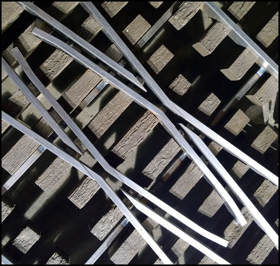
Next is just a picture I forgot to post. Somewhere in all the last posts, are a couple about the diamond crossovers. In them, I mentioned
the angled pieces I make so that we can form the diamond. This is a closeup that clearly details how we use them.

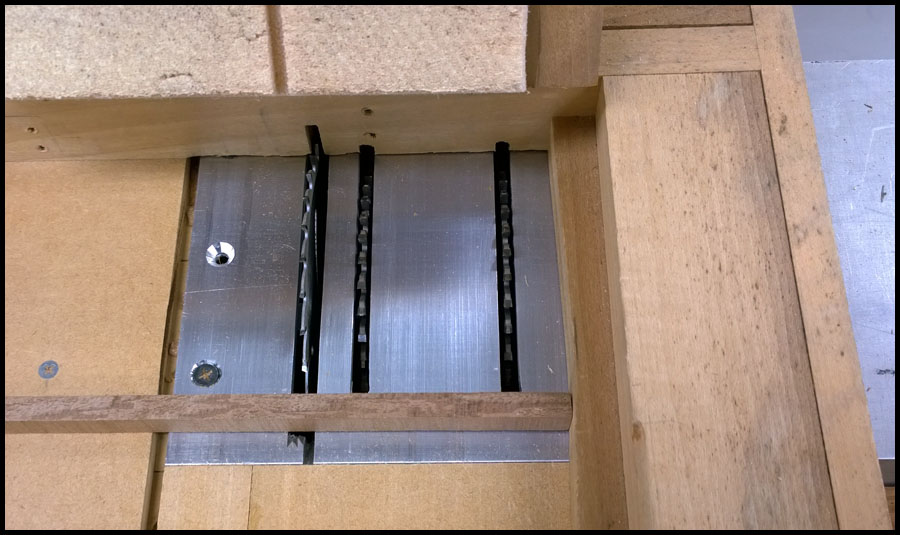
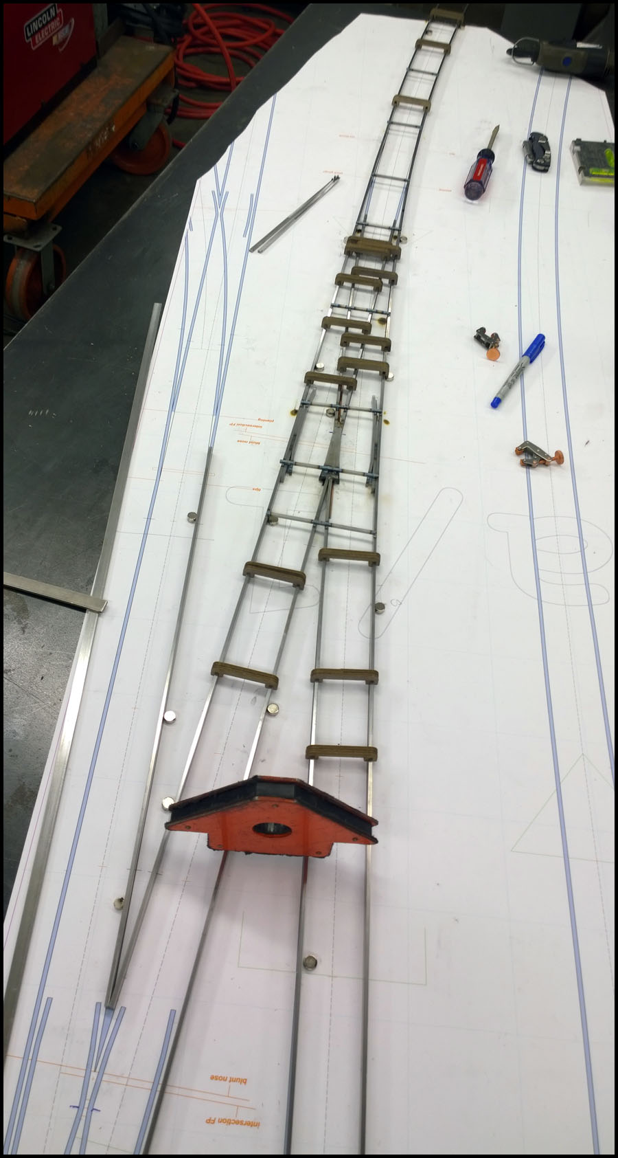
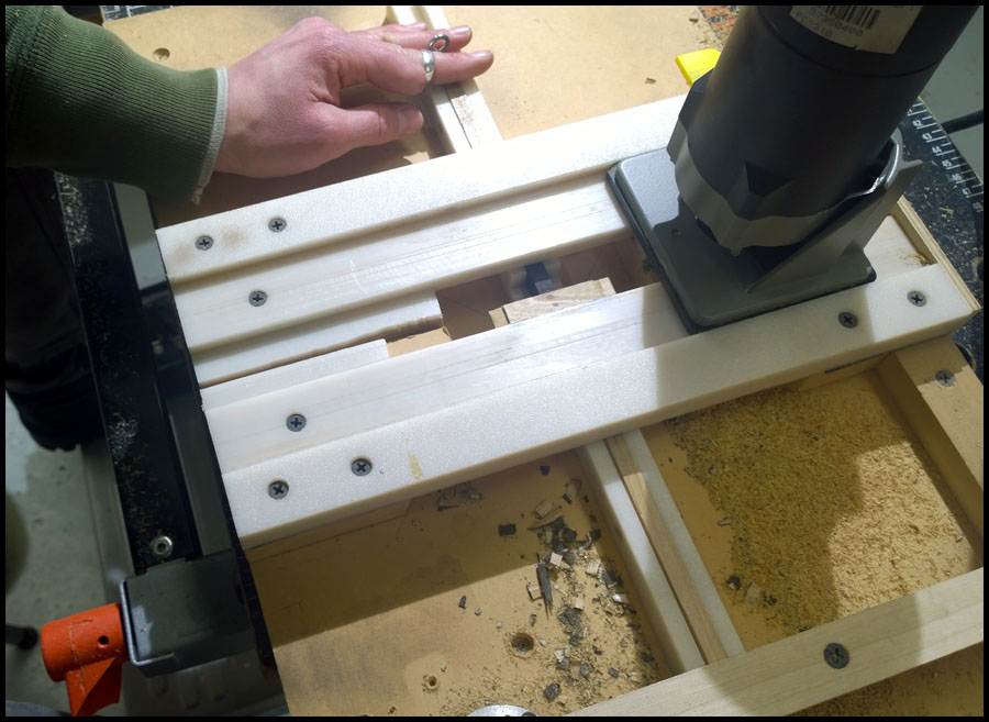
Next up are some pictures of the tie making machine. This cool contraption was built by a fellow named Jim who used to do a lot of the infrastructure
work on the railroad, and was instrumental in its original construction.

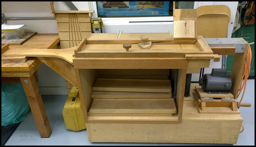
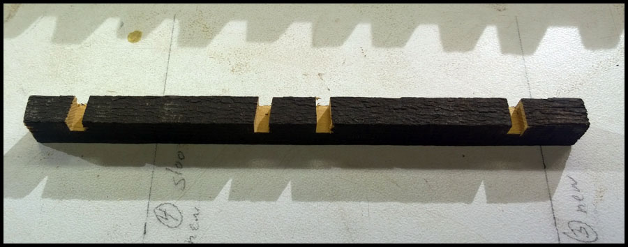
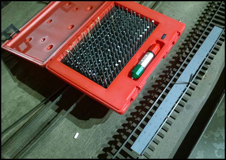
This is a picture of the spindle, which uses two 3mm(.118") blades to cut the slots. This gives a nice press fit on the rails. A sample strip of tie
stock is in the picture. In use many strips would be stacked and pushed through at the same time. The table rides in slides that can be seen
in another photo coming up.

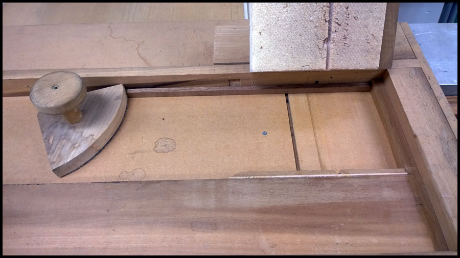
It is hard to tell, but on the right side of the tray, a scallop is cut into the stop surface to the right of the blades. This scallop, allows the ties a
small amount of variability in length.

When the tray is pulled back away from the blades after a cut, you use the pusher to move a fresh stack of strips into position for a cut. Here
it is easier to see the scallop. Also, the tray would normally be full of much longer strips, but I didn’t have any ripped to length while taking
these photos.

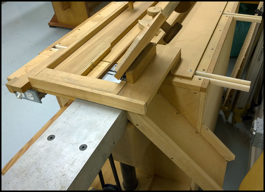
From the rear of the machine you can see the exit chute that cut ties slide down into a bucket or box. You can also see the slides that allow
the table to freely move across the blades. A lid pushes down with foam to keep the tie strips in place during cutting. Something has gone
wrong with the spindle during the last use. The cut off blade is now wobbling around. I must remove the spindle and repair whatever is wrong
soon.

We must go work on the railroad some more. It is a sunny and warm day here in Portland, and I am feeling much better.

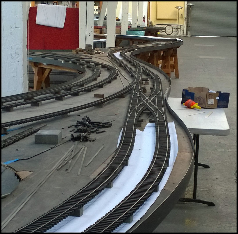
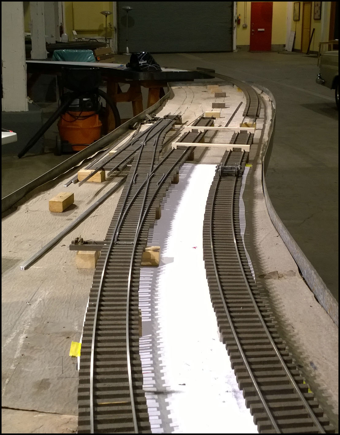
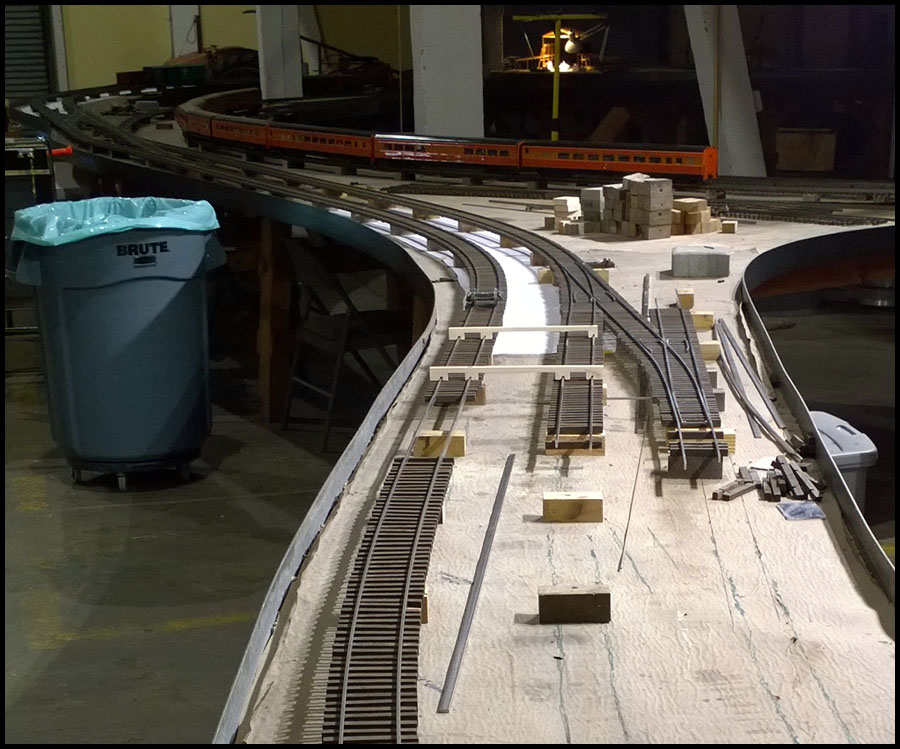
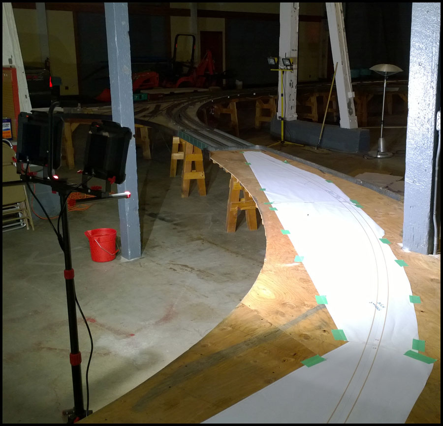
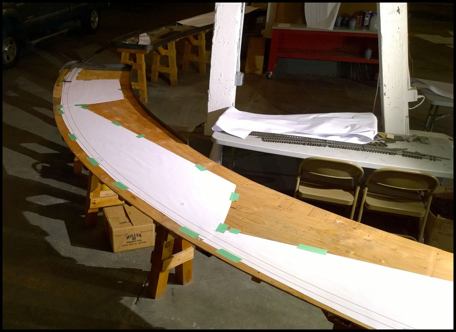
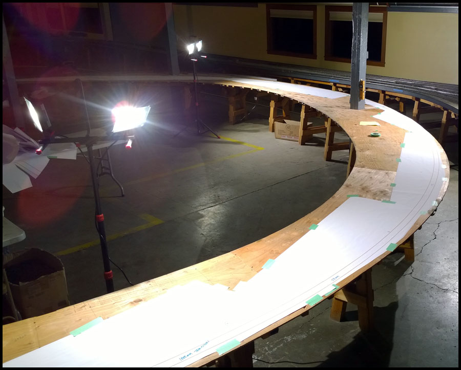
Next posts will be track work again. I have been editing photos to tell the story of how and why we tore out the middle loop and
are starting over, and how the new approach is paying off. I will try to post more often this week. Pictures are done…just need time.

Karl

Thanks for the updates.

I’m really enjoying watch yous guys doing the work .(https://www.largescalecentral.com/externals/tinymce/plugins/emoticons/img/smiley-laughing.gif)

Karl, I hope you don’t mind if I post a link to this thread on the major UK-based garden railway website, gscalecentral.com. A few of the posters here are also members there. It might be a good idea for Dan Pantages, David Leech or Peter Szolga to post a link to the Gauge 1 NL&J - I’m totally positive that the many Gauge 1-ers in UK and Yoorup would be fascinated to see what goes into making Stavers the enormous success it has been over the years. Dan and a few others know that we come over to Portland and places South at least once a year, but our visit has never managed to coincide with a meet, which is, for me, a real tragedy.

Epovah, next year, with the big show happening in PDX, we’ll manage to coincide our home-trip with a visit!

Best from over near, near Belgium.

tac

Ottawa Valley GRS

Port Orford Coast RR - Eastern sub.

Hi Tac:

Feel free to link to these posts. Larry is not paying me to do this, it was my bad idea to spend what few extra minutes I have posting online.

That said, I think Stavers is one of the coolest places ever, and I don’t think Larry or the railroad get the attention they deserve…at least from the
many that have never been here. But how is anyone to know whats going on here if we don’t talk about it once in awhile. Also, it just
seems to me there used to be a greater quantity of interesting stuff to read on the live steam forums, and I thought this would be an interesting
story to tell the community.

Its not that often a large railroad like this gets torn up and rebuilt with interesting techniques.

I spent the morning editing the last pictures needed before I can start posting about track building again. I hope to have time in the morning to get a
post up.

Happy steaming

Karl

Hello everyone:

Feeling much better these days, and we are extremely busy at Stavers. Jenn and I have removed about 50 more feet of mainline that we built this winter, including the
west yard throat and salvaged curved crossover from earlier posts. After designing a couple different yard variants, it became apparent to Larry and I that trying to
follow the old alignment was creating a very tight yard entrance. Also, the yard throat I had installed in December was located on the adjacent passing track of the
mainline, and because of the alignment, any moving of trains or cars into and around that side of the yard, would mean the passing track would have to be used, creating
a traffic problem. So the yard throat needs enough track so you can build a train in the yards without moving on to the passing track of the mainline.

If we rebuild the table top to accommodate a different angle exiting the middle yard loop, then many possible options become available. So I redesigned the yard for
much improved usability. The track work will be nothing like what was in this loop before…however, I start telling that story after this post.

This post is about the yard throat on the other side of the loop, we finished this track work about two to three weeks ago, and after this post, we will be catching up
to where we are working now on the railroad. Although that will take us back two months to the beginning of that aspect of the story.

Here is a picture looking into the building along the mainline facing east. At the end of this stretch of track is the beginning of the middle loop and the associated
yards we need to build. We need a yard throat just on this side of the bridge where you enter the middle loop.

When we first started thinking about the yard throat for the entrance to the yards when heading east, I thought I would be able to use a couple salvaged turnouts. No
matter how I aligned the best options out of our old turnouts, the alignment wasn’t going to work. So I went to Templot and designed a similar set of turnouts, took the
printout over to the railroad and this is what it looked like…

I didn’t want an “S” curve with no lead straight, and Larry agreed, so back to the drawing board. I went back to Templot and thought of a different
approach. This is what we ended up deciding to build.

First step after final decision is to print out the inverse of the switches on 46# paper and Jenn can start bending rail. A #8 turnout is used on
the passing track of the mainline, and a #7 is used on the yard. We have also decided to start making all our frogs with the new shorter
method, so I had to modify a couple for Jenn to use during construction.

So this shot shows how we layout the pre-bent rails and the frogs using very strong neo magnets. Jenn is getting very good at bending rail fast
and accurately.

We also use the laser cut gauge separators to make sure everything stays mid gauge. As usual, we will clamp straight edges where appropriate
to keep everything aligned during welding. I couldn’t find any images of the assembly all clamped up, must have been focused on work that night.

Here is the assembly all welded up, just needs points and ties. I took this shot outside in some interesting light, generated by the low winter sun,
just about to go below Portlands West Hills in the late afternoon. The turnout in the drawing that we’re not building is because we haven’t finalized
the design going that direction…we will build that out later.

Took the assembly inside for a test fit…like a dream, should be an easy install.

Now Jenn has to make ties again while I move on to working on designs for the yard.

Here Jenn is finishing up installing ties using some laser cut tools. Since Larry has a laser, I have used it to make us many helpful tools. These
help Jenn space and align ties.

Here Jenn is about to cut a slot in a tie by sliding the router across. If you look closely, you can spy one of the many reasons I love Jenn…
She has been pre-disastered in a hydraulic wood splitting incident. Since we own a machine shop and work with tools, she has already
learned an invaluable lesson about the unforgiveness of machines.

Here is a tie after cutting and ready for installation. We don’t try to make a tight press fit, there just isn’t enough precision and it would result in
many lost hours. Instead we route them slightly over size and glue them in place.

And finally, finished and installed. Looking to the east and the entrance to what will be a large storage and steam up area.

Looking back to the west…

We are about 1/3 of the way through re-sheeting the middle yard loop for the increased size of the yard…now we must go finish the next third
so we can start building the yard. Last weekend in April is approaching faster than my GTO…

Happy steaming

Karl

Man Yous guys make it look easy…

Hello to those who are still paying any attention. I have a few minutes before heading to work and thought I would post a few pictures and
get started explaining why we tore out 75 or more feet of railroad we just finished building.

Jenn and I are very busy trying to get everything done in time for the steam up in a few weeks. Right now, we are building a connected
series of four curved turnouts that are part of a network 7 turnouts that make up that section of the new yards. Although we can print up to
10 foot lengths at 2 feet wide, our welding table is only 8 feet long, so I fit as many of the turnouts as we can to build at once on the table.

Finally got a new to me camera. Nikon D7200 with Nikon 40mm Macro lens and a nice Nikon 18-140mm. It takes stunning photos of my cat so far…
The macro lens is excellent for photos of machined tiny parts, and the 1080P/60 frames will allow for slow motion analysis of machine operations on my cnc
lathes and mills. Something I’ve been doing for years for process improvement and/or diagnosis of operational problems. Anyway, hopefully some
more consistent photos and better light sensitivity.

Back to trains…While Jenn and I were building the track work in December, Larry was getting good at designing turnouts in Templot. Our problem was that
to be able to design turnouts for curves, we would have to know the exact radius of the existing track so we could fit it to that track after building. Larry
was experimenting using chord length measurements to find the radius at different points on the track. We even purchased a special dial indicator that takes
a depth reading and automatically calculates the radius. Problem is that it is so sensitive that it is very difficult to take consistent readings. It is designed for
smaller radii. I think if we build a fixture for it that uses the track for stability we’d get good results, but it turns out we could get satisfactory results going
back to basics.

So the real issue, is that in the double track we had already built, including the curved crossover and yard throat, we found that the radius varies wildly in
any given length of just a few feet. In order to design a yard in Templot encompassing all of the area of the yard loop, and know the turnouts would align
correctly, we would have to have a very accurate representation of the entire curve around the yard to use in Templot.

So I started measuring the curve back in January, and this is how I did it. A brand new, precision Starret 18" ruler, and a precision ground pin set were used
to find the chord height. Made a mark at each measurement, and then shifted the ruler 4.5", and recorded another measurement…113 or so times, it took hours.

We then needed to build the Templot track pieces one 4.5" section at a time to recreate the existing curve. But first I needed to load a spreadsheet cell
or two with measurement data and some equations to calculate the radii and swing angles so that the short sections of curve could be created.

This picture is a subset of all the measurements so you can get the idea…this is actually an updated spreadsheet to the first one we did. We built
the curve using the original calculations for the arc angle(swing angle in Templot), however, it didn’t fit our cad overlay of the building posts and
such, so I knew something was wrong. It occurred to me that with the changing radii every few inches, there was know way to know if I was
calculating the arc angle based on the beginning or end radius of the curve, so I averaged the before and after measurement in the second
to last column, and used this to generate the curve, it then fit remarkably well.

At this point the Templot representation of the curve showed us exactly how bad the situation turned out. Each
individual curved piece has a cross hair located at the radius center point. And it generates a sort of scatter plot
that shows how many radii there really are in an obvious way. To design track work and a yard to fit this would
negate the new found precision in which we have built up through the yard throat.

So I decided it might be useful to graph some of the data and see if we could figure a way to average the curve, or break it up into a few sections.
This graph is of the averaged vs. individual calculated swing angles. We just wanted to see how the average was smoothing the curves. In the graph,
blue is the averaged, and you can clearly see that the smoothing of some spikes that most likely caused the first curve to be not quite right.

The next is a graph of the individual radii. So even though the curve looked nice in place, Larry just couldn’t
bring himself to build this large new yard and not be able to use Templot to lay it out first. So…tear it all out said Larry, and the day after the
March first Tuesday operations session, out it all came.

At this point, we now have to design a replacement curve to fit the area. Larry wanted to try to hold it to a maximum of three separate radius, with
proper transition curves between them. I was able to succeed, and this is the replacement curve. You can see only the three radii near the center.
The other two at the top of the curve are for the transition curve from the yard throat side and were already accounted for in construction.

And here the curves are overlaid, with the original in blue and the new curve in red. Now I can start work designing the yards and we will
rebuild everything at once which will then be the same as our Templot representation of the railroad.

So we printed out this curve on lightweight paper to make sure it would fit. Sure enough, it fit perfect, aligning at both ends…however, it takes
quite a bit of smoothing and slight shifting of the paper templates to make sure they are laid down flat and wrinkle free.

This picture show the west yard throat area. We have now torn out the curve on the other side, and the tables will be rebuilt to allow
a better angle across the bridge and into the next curve.

Here is where the curve ends up at the now completed East yard throat.

And finally, an overall view of the curve laid out on the bench work. We are about half way through rebuilding the bench. I started by folding the
paper back past the first transition curve from the east, then rebuilt the top of the bench up to the transition in the bottom of the next picture.
Then we rolled the curve back out and marked the locations of the transition curve start and end points on the new surface. This gave me the
points I need to lay out the printout of the entire new yard all at once and have it align. We then removed the printed out paper curve and tore
the top off the rest of the bench work.

We must go to work now, many turnouts to build. Next installment, the yards I came up with and perhaps the tandem turnout build pictures.

Happy steaming

Karl

Edited to include picture I forgot to link

Reading back a bit, what glue do you use for the rails in the ties? How do you clamp the rails while the glue is setting.

And I’m sure there are many people following this, so post whatever you want, don’t worry about people being interested, we are!

Regards, Greg

Yup, what he said…(https://www.largescalecentral.com/externals/tinymce/plugins/emoticons/img/smiley-wink.gif)

Image result for sheldon trainI think he understood what you were saying…(https://www.largescalecentral.com/externals/tinymce/plugins/emoticons/img/smiley-laughing.gif)

Great work and write-up…

9 days and counting.

3 days and counting.

Who’s counting?? Hope Karl and Jen got some steam up bays restored along the way!!

See some of you tomorrow and the stragglers Thursday.

So I’m going to take a few minutes for an update while Jenn is installing ties on the mainline. We have only had one day off in the last 3 weeks or so and that was only so I could do my taxes.

It became painfully clear last month that we weren’t going to get everything done for the steamup…all we could do was keep building and hope for the best. We’ve been working 10-12-13 hour days
the last couple weeks and even 15 hours yesterday getting home at sunrise in our attempt to get the railroad ready.

The outdoor loop has been reinstalled, a temporary indoor return is installed in case it rains, and we are about
60 feet away from having the mainline completed as of this writing (4-24-2018 at 7pm PT). We should get about half or more of that done this evening and the rest tomorrow. There are no more bridges to
build so trackwork is moving fast.The new yards are partially built and we will continue to add as much as we can tomorrow.

We have created a drawing and cnc programming that allows us to create any angle frog easily by only changing the angle. Solidworks will automatically create the new frog geometry and cnc gcode based on
the cutting parameters I built into the process…its pretty cool really, but I am very tired having spent way to much mental effort the last few weeks learning the new cam system.

This will be my last post for a couple weeks. After the steam up, Jenn and I are going to Astoria for a few days to visit a steam locomotive, sing karaoke, and maybe fly a combat kite. Also, I have a Quadrajet carburetor, a 66
Pontiac tri power carb setup, and a pair of carbs off a Triumph TR6 to build next week because everybody is waiting for me to finish working on the railroad so much. No more carbs after this except my own…

To the question from Greg about the glue we use. It is a flexible sort of super glue made by DAP. Its called Rapid Fuse and takes about 30 seconds or less to set. So far it works great. We used to use liquid nails, but the
results were far from satisfying and ties did not stay put well at all.

Back to the build story…

Starting with the new yards, we used Templot to design a few iterations, but this is the final design we are building…

This is a huge change from what previously existed. It was a single track mainline with a couple of oddball steamup tracks. Although it looked interesting,
functionality was limited. This new design expands the storage and steamup areas dramatically. The return track colored in red may not be built, a final
decision about that will be made after the steamup. It would be nice to have a circle for testing locos so you don’t have to walk the whole railroad.

In preparation to build the new yards, the table top needed to be torn off, new infrastructure built, and much larger table top area installed. While
getting ready for all that…ordering wood and making plans, Jenn and I started on the tandem turnout that is the beginning of the yard ladder.

Here is a Templot screenshot of the turnout to be built. As usual, we print the inverse and build it upside down. This cool switch uses a #7 and two
#10 frogs.

Here is some of the parts spread out in preparation for welding.

You can see that we use a lot of neo magnets in our builds. This is both a blessing and a pain in the rear. The magnets hold the parts well, but sometimes
just decide to attach to something unintended, or parts snap up off the table to be on top of the magnet instead of next to it. Still, using them works
and makes life much easier. Here Jenn is holding a pair of welding pliers to hold and place a magnet.

Ready for ties…

That’s it for now and the next couple weeks I think. I might get exited and find time to post. I am learning my new camera and continue to document
our progress. Many pictures are ready for posting, but I have a railroad to build…

Happy steaming, and Jenn and I look forward to seeing everyone this weekend.

Karl

Hi everyone:

Just a quick note about this steamup weekend. First, we finished the mainline at 8pm on Wed, and stayed till 4:30am (18hr day) to add steamup track to the yard loop.
Stayed till 3am Thurs and completed one complete through yard track and some sidings. Finished a second through track yesterday afternoon during a lull
in operations…whew…Jenn and I can barely stand.

However, it has been great to see everyone, the track has performed near flawless given it was almost all untested.

So lastly, the live at Stavers cameras are working, and you can see the action now and all day here…

Live Staver spring steam up camera page

Happy Steaming and I’ll post more build story and pictures when we recover.

Karl

I see 5 cameras, but 4 of them are focused on scale figures and vehicles, don’t show the layout at all (1, 2, 5, 6)

You are using bandwidth for all 4 of them but not showing any of the trains running.

Also, you should set the brightness of the single camera showing the layout, since it’s pretty dark.

Would love to enjoy it and see 5 times as much…

Greg

Hi, Karl. Any updates about what you guys are doing this summer?

Rob

Karl, I have been following your progress with great admiration for everything you all are doing. It looks great! I am coming up to Portland next week to meet my new grandson. I ran into Larry at the NSS today and spent a little time chatting especially about the live feed camera set up. I am planning on coming to the open house on the 21st and am looking forward to meeting you!

Greg Hile.

My family and I had the pleasure of visiting yesterday at the Open House. As one person said in a previous post, it has to be seen in person to fully appreciate, and they were right — photographs alone just cannot do the facility justice.

A couple observations:

There were a number of visitors from the other event across the street who were totally unaware of the news about Garden Railways and Marc, who were in the dark about Cordless Renovations and other vendors closing their doors, who had yet to take a position in the ongoing debate between track power versus dead rail, or lamented the lack of NMRA LS standards, or who even knew what large scale live steam railroads were for that matter. But they all appeared to be pretty fascinated by what they saw.

Perhaps no more so than my son-in-law, Aaron, who took excellent video of one of the trains operating, and started designing a layout as we stood there. He had never seen a LS layout before but he was enthralled by what he saw and is looking forward to NGRC 2019. (In the interests of full disclosure I do need to report that Silas, my four-month old grandson, was less impressed than his daddy, but we’ll work on him.)

Many, many thanks to Karl and Jenn for their gracious hospitality, and of course for all the incredibly hard work they, Joe, Larry, and the rest of the crew put in. All in all, it was quite uplifting for those of us who sometimes fret about the direction our hobby seems headed.

The Other Greg