Large Scale Central

Big changes at Staver Locomotive for Spring Steamup

Thanks for the comeback Karl, your explanations help us all understand the “flavor” and how stuff works. The web site just gives the location and the steamup info, it sort of implies “drop by any time”. The history and the players would be a welcome addition to the web site, but I can easily see you all have your hands more than full!

I hope to visit some time, the trackwork looks awesome!

Greg

Had a busy day yesterday and no time for posting. I’ve got a few more pictures to post of progress at the end of December.

After the mainline loop was finished, it was time to start doubling up the trackage. This picture was a day or two after first Tuesday
operations. I can tell because the stacks of ties were delivered by work trains while we completed this section.

When joining two sections of already laid track, we install an expansion joint. In this case, the radius of the turn increases as the track exits
the curved crossover. I prefer, when possible, to put the expansion joints in straight track or the widest radius available in the work zone. After
building the double track in the last picture up to near the point of greatest radius, we switched to building from the curved crossover to meet up
with and install the expansion joint with the other run. The joints are basically tongue and groove, I will try to remember to get a picture of one.

Trying to join up two sections of track on a curve is very difficult without an expansion joint. Even a few thou of an inch will cause binding when
you try to install the last few ties and the track gets forced out of gauge by the mismatch. The expansion joint needs about .025-.03" gap to
work well, so I can grind the track to size with a little lee way and join the sections in perfect gauge.

In the next picture you you can see the final ties being installed for this section, somewhere in there is the expansion joint, but I didn’t think to
focus the camera on it. You can just make out one of the rail butt joints after welding. We weld the rail on the outside only to provide smooth inside
edge of the rail for the trains. Experimenting with different heat settings and welding techniques, we arrived at a process for connecting the rails
that has served us very well.

Instead of trying to weld a small bead along the outside rail joint(which leaves a slightly raised surface), we settled on a higher temperature, and Jenn
melts the rail together without filler rod. The bottom third of the rail flows together, with the puddle shrinking inward slightly and leaving us with a
surfaces that ties will fit over without grinding, or we can clamp a straight edge against while building long, straight runs.

A closeup of one of the welds. This doesn’t look bad, but the welds look better in person. This angle makes it look different than what I see with
my eyes, but the penetration is obvious. We don’t need the weld to penetrate the entire rail for the joint to be plenty strong for what we do.

Ive got time for a couple more pictures, but must first head to photoshop for a few minutes to prep them.

Back soon…

Karl

Back again…

While building the section in the previous pictures, Larry and I were also making plans for the other areas of railroad that need reworking. When
trains come back in the building from the single track outdoor loop, the mainline encounters a turnout splitting into a passing track. Because of
changes to the yard throat in the middle loop, and the interchange for running the inside loop when its raining, and the limited space for
building the interchange…we decided to build a second diamond crossover. Building the first one went much smoother than we thought it would,
and when I realized I could use special mill fixtures I made for frog production to produce all the angled pieces needed for the crossing, I made
enough more parts for four diamond crossovers. There are 24 angled pieces per crossover used to create the diamond. More on the parts for
crossovers later.

This picture is the Templot template created for the crossover. and this is the approximate location for it…

After completing the loop up to the curved crossover, it was time to start building the newly double tracked section around the inner middle yard loop. Here is
a shot of the middle yard throat with a salvaged turnout that fit like a dream in this section.

Same basic shot from the other direction. this is the curve with super elevation that I left in place. I spent last night with the tedious job of grinding through
about 40 welds so I could remove the inner steel wall of this loop. We are rebuilding this section of benchwork to provide more space for the yards and
associated steam up areas and storage tracks. Although the mainline is 8" track spacing, as well as all adjacent tracks, Larry has decided that this yard
will be restricted to trains that can fit withing 5.75" track spacing of the yard trackage. This is still scales out to 15.3’ and and is wider than most spacing of
12-14 feet in yards. 14’ in scale is 5.25" spacing. Although we did quite a bit of research on prototypical track spacing, Jenn and I also went down to the BNSF
yards with a tape measure. Many of the people who run European prototype 1/32nd trains have traditionally used this yard, so we decided having more room
through less track spacing would be prudent.

While we are building inside, Larry, Joe, and I consult and try to figure out what to build outside. Here is a picture of for what is now, the basic layout for outside.
We use a lot of PVC pipe to layout possible runs for the mainline and indoor to outdoor interchange possibilities. Larry is always open to changing his mind, so
this may or may not be a final configuration. But it is close enough to allow Joe to start on some infrastructure to build it. We have torn all this temporary stuff
out already, and Joe has been busy pouring concrete and such for the last few weeks.

Larry has some space to fill with trains…more pictures of outdoor work to come.

Time to go work on the railroad.

Karl

Very cool thanks for sharing!

Have time for another quick update.

It was time to complete the mainline loop around the 1/32nd yards.

We started building from the top of the loop.

This shot shows the rail after bending. It holds its shape quite well as we build out around the curve. This area is tough because the table was, to
some extent, built deliberately a little rough in shape so things didn’t look to smooth. Holding a smooth curve, while leaving as much room for the
yards to be built as possible, and still being able to hold the alignment to the bridge we are heading toward, was a challenge. In a future post, I
will describe a method we use to actually measure the curve accurately, and then virtually build into our Templot plan of the entire railroad.

Although this curved turned out nice, and the trains look wonderful traveling around the big curve, and we had a fair bit of time invested in building
it all, once we measured the curve, Larry wasn’t satisfied with the amount of changing radius’ around the loop, and wants to build the curve using
Templot to create templates to form the curve and transitions. Since the table is what forced the tracks alignment, two days ago Larry told me
to tear it all out back to the bridge by the yard throat, rip the sides off the table, and rebuild the curve. We will widen the table as needed to get a clean curve, built to
spec, and let that drive how much we change the table, as opposed to building the railroad to fit the table.

So all the pictures in this post, are of track that will most likely be gone by today. I can see some long hours coming in our future…

It isn’t that there was anything “wrong” with the curve, Larry has simply decided he wants to rebuild almost the entire railroad using much more
calculated techniques than they used to build the railroad years ago. Back then it was pretty much…“that looks good, go with it.”

This shot the mainline curve is close to finished, and the double track is moving right along…

Here is an overall view of the mostly completed curve. Looks nice, but it is amazing the the total number of different radii in any part of the curve.
I completely understand why Larry wants to rebuild it…but April is coming fast…

The next shot shows where we stopped work, this was 6 weeks ago, long before we decided to measure it and tear it out. We stopped before the bridge
for a couple reasons. One is we didn’t want to block the entry way to that loop until we had the track ready to build a three track bridge crossing. Second,
we had to decide and design the interchange and yard throat leading up to the bridge from the other side.

That’s all for now, next time I will show what we built coming from the other direction. It was all built using Templot and turned out excellent.

For now though, out of time, must go demolish our hard work.

Karl

(Edited to include picture I forgot earlier)

Sorry guys, haven’t had time to post last couple days.

Talked Larry out of demolishing our curve until after first Tuesday. We hadn’t any plans for the replacement anyway.
So instead we dove into installing switch stands and completing the temporary inside loop. We finished last night at
midnight. Also finished designing the new curve, so demolition will happen tomorrow.

However, I am posting right now because first Tues is happening, and Larry has a live camera traveling the track. For a
short while longer, you can go for a ride along at this link.

Live train camera at Stavers

Alternately, you can click on Live@stavers on his website home page.

Hopefully the camera will keep working for an hour or two more…

More pictures and build story to come, but I need to find some time first.

Thanks and hopefully happy viewing

Karl

Hi all:

Well the video link was probably anticlimactic for the few that might have seen the post in time…it was working quite well for a short while, unfortunately
the guys had started winding down for the day. When on the website, the two current camera feeds on the “live@stavers” page, are actually hi resolution
micro video cameras pointed at scenes Larry likes to set up. Each camera is controlled by a Raspberry Pi, and the video feed transmitted through a high speed
wifi connection. During future steam ups, the plan will be to have feeds around the building, the track, and in trains. From the web or your phone, you will be
able to access the feeds at any camera and watch the crazy action that is a live steam event at Stavers.

I captured a few pictures of the 1st Tues event yesterday, but will follow the basic timeline of the build story and post them at the appropriate time.

We came up with a curve that will fit the yard area, and a yard throat design. So demolition of the middle yard curve and table edge will commence today.

In the mean time, we will return to the build.

So at this point in the work, we needed to design the interchange between the outside, and the inside loop interconnect, and also consider traffic needs
for entering the yards, and/or exiting the yards for bi-directional operations. We began this process by setting Jenn upon the task of making the four
turnouts needed to construct the diamond. In the mean time, Larry and I began working on the design for the interchange and drawing it up in Templot.

In future posts, I will discuss Templot and how we use it. The important thing to know here, is that Larry and I were getting good enough with the software
that Larry decided we should use it to build the railroad as much as possible. Our success at this is what let to the decision to tear out the middle yard loop
the other day.

To start, I will show the progression of the diamond. Over the next day, Jenn built the four new #7’s we needed using our tried and true jigs I made 5 years
ago. I will show pictures of those at a later date. The next step is to lay out two of the turnouts on the welding table and align them by the V-crossing of the
frog. Also, we set the 8" spacing and then weld a couple .125" x .25" braces across the turnouts to lock them in place. All the while, we have .25" x .375" lengths
of high quality steel to use as straight edges using 1" throat Kant-Twist welding clamps to hold our work in place.

Once the first two turnouts are square to each other, and the straight edges clamped and aligned, we can use the straight edges to locate the 3rd turnout.

Once the 3rd turnout is put in place we clamp pieces of straight steel here and there to lock things into place and start building the diamond. I start by cutting
the straight rails for the mainline tracks as close to length as possible, then use the micro chop saw with cut off wheel to trim the final few thou off until the
rails fit perfect and Jenn can weld them. This next pic shows that already completed. Here we are using some of the 24 individual angled pieces needed to
create the diamond.

All of the angle pieces are made just longer than the shortest we need. The rest will need a straight welded to them, but this is key to our process…we clamp
the angled piece in place, them trim a straight just longer than we need, and weld it together. Now we trim the length overall until it fits as well as I can get it,
and Jenn will weld it in place. In this picture, you can see some already installed, and one laying in the middle ready for trimming.

Making all the short angled pieces the same length is what allows me to set up a fixture in the manual mill, and make lots of them fairly fast.

So far the process is actually pretty straight forward, and on the two we’ve built the results fantastic for using no jigs or setup fixtures other than clamps and
straight edges. The next steps, to fill in the diamond are a little tougher, but still goes smoothly and gives excellent results.

Here I did make some helpful set up tools. They consist of two straight pieces of rail, with cutouts that allow us to overlap them in the crossing. In the picture
you can see them clearly because they are marked in black sharpie for contrast so we don’t get confused looking at the assembly. If you look close, you can
see where the cutouts are so the rails can overlap. The overlapping pieces allow us to clamp and weld all the rest of the components in place. After we are
done, the set up parts can be removed by pushing them through to the front of the crossing.

Here is a Jenn action shot. She is just welding the last support piece for the turnouts. In the box at the front left in the picture, is a stack of the angled pieces I made…I think I made about eighty of them on the
second run, so we have enough left for three more diamonds. The parts will only work for #7 crossings though, if we switch to #8’s outside for the mainline, I will have to laser cut a new fixture and make more
at the #8 frog angle.

Almost done…just a few more cross braces and guard rails to weld…tomorrow comes the tedious job of making and installing the ties. While Jenn makes the ties I am in the process of designing a new switch stand.
It will take Jenn about 10 hrs to make the ties. We have ties of proper length pre-cut in bulk so Jenn can choose the appropriate length, take it to the slot angle cutting machine, and cut the slots.

Our switch stands, by and large, have served us well but are difficult to install and adjust in our application. Also the nature of our installation has had clearance problems with some locomotives. So while Jenn was
tied up for a few days (pun intended), I set about designing a switch stand we could laser cut and solve the various issues in an easy to install package.

That’s it for today. Last shot is the finished crossover ready for ties. We laid it out on the track for Larry to see in the morning. We use clamps and old track,
and lengths of rail, to mock up and visualize the track. Now we do a lot of this with plotter printouts from Templot.

Back to the railroad.

Karl

After finishing the crossover, we had settled on the interchange of the inside loop interconnect. This next picture is what we came up with…

We welded the crossover to the road from outside outer curve to setup the alignment and help keep it in place. We knew already that this entire curve and entry turnout would be replaced in a couple weeks.

This interchange was designed in Templot and was our first attempt to build the track and see how closely we could model it with the software. It worked out well, and because of this, the diamond crossover
and inside loop interchange are the starting point from which everything else will be modeled and/or built. Here is a screen shot of the interchange in Templot. This can be printed out on our plotter and matches
the track work extremely close.

The triangle in the middle curve signifies the start of the transition curve. The ] to the right is the end of the transition. These can be easily
modified and always form a spiral transition. The turnouts are #7 and match our turnouts. There are ways to measure various aspects both
in the software and the real world to allow us to model the railroad accurately, and know that we built it accurately. More about some of
those methods in future posts. The interchange allows trains on the inside loop to go directly to the mainline, or switch to the passing track
which will lead to the yard throat.

The next picture shows the just completed interchange, and a Templot printout of a curved crossover Larry would like built. Once we found that
#14 frog would work well in the crossover, Larry decided it would be best to replace the one I salvaged with and identical #14 crossover. This
would mean four custom curved turnouts before spring. I suggested we build one first for the replacement on the road from outside, and hone
our skills. Also, I had an idea for modifying the frogs that we wanted to try on the larger number turnouts. More on this modification when I
discuss building the switch.

At this point, we began planning the new road from outside. We printed out a #14 curved turnout in heavy weight paper, and Jenn set about
pre bending rail and parts for the turnout. More on building the curved turnout in a later post. In the mean time, I designed a transition curve that
would work to further the track toward the yard throat.

This time, Larry and I decided to print a template of the curve, and attach it to the table in the location to be built, and build the curve right over the top of it.

This worked out well, and I can measure the distance between printed transition start marks, to find the distance between the curves, and build
model into Templot. One more shot and then back to the railroad.

Today we start building the turnouts for the yard throat at the end of this section of track.

Weather is getting warmer, but it still gets cold in there at night.

Karl

Very elegant track work, the Commodore in the observation won’t spill a drop at speed! (https://www.largescalecentral.com/externals/tinymce/plugins/emoticons/img/smiley-foot-in-mouth.gif)

It is nearly impossible to say enough good thing about Larry, Karl, Jenn and all the crew from the beginning of Larry’s layout right through to today. This includes all the people who help Larry during steamups to take care of us all with exceptional hospitality. Larry’s layout has to be seen in person to be believed.

Larry’s layout, I believe, is the best steamup layout I have ever experienced. It might even be a reason to move to Portland - but that would still take a lot of thought.

Now if Larry just had some control over the weather in Portland. At least it’s rain and not snow. And now Oregon is beginning to let you pump your own gas.

Thank you Larry.

End of rant.

Thanks for the comments everyone. Sorry I haven’t posted in a couple days, been feeling a little under the weather. Got a really mild cold, but enough to make me tired and achy.

So here comes a few pictures of the #14 curved turnout Jenn and I built. I didn’t get many pictures because it actually went really smooth and before we knew it, the turnout was
basically finished. I took some pictures yesterday of the turnouts partially built for the yard throat that will show more detail of our methods. Until then, here is the curved turnout.

First, we start by creating the Templot template for the turnout. With the bridge installed to the outside track, we used long sections of steel, and a chalk line, to find the angle of
the curve. At the center point of the of the angle, I can measure to where we want to start the transition curve into the building. Once we know this distance, we can go to
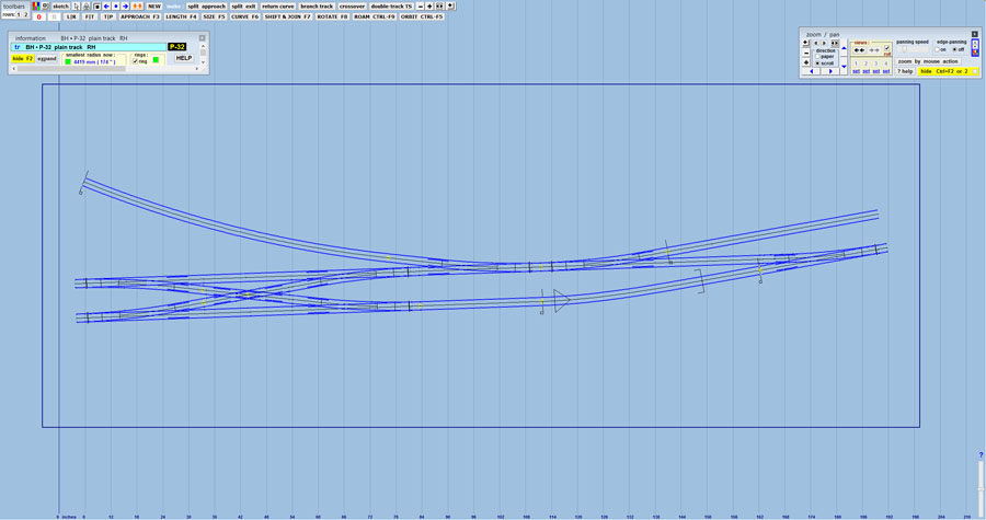
Solidworks and generate a .dxf of the angle, import it into Templot, and then create the curves and the turnout and know that it will fit. We now have a few more tools to help
us perform these measurements more accurately. I will discuss these at a later time.

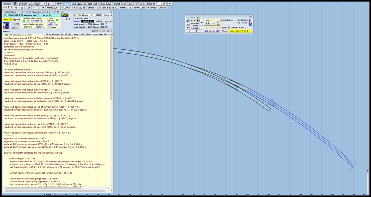
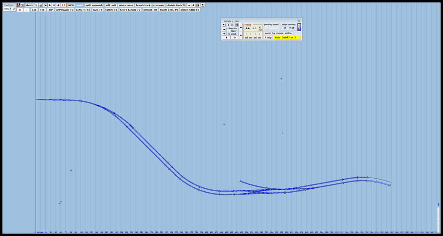
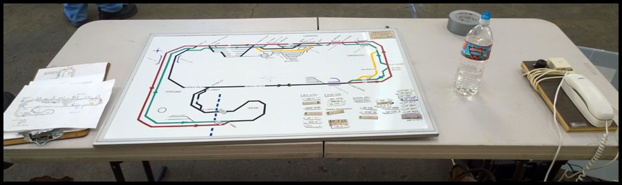
Here is a picture of the turnout generated in Templot. You can see in the open window on the left, more info than you can imagine on the characteristics of this section of track.

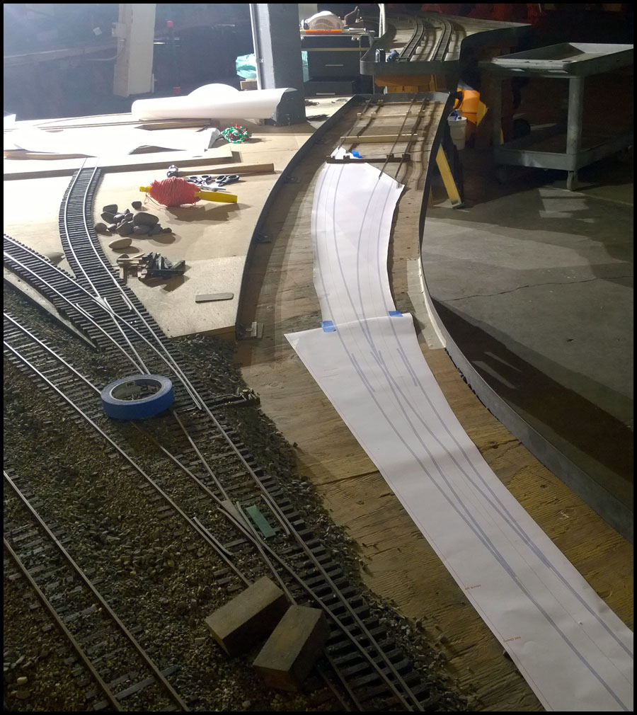
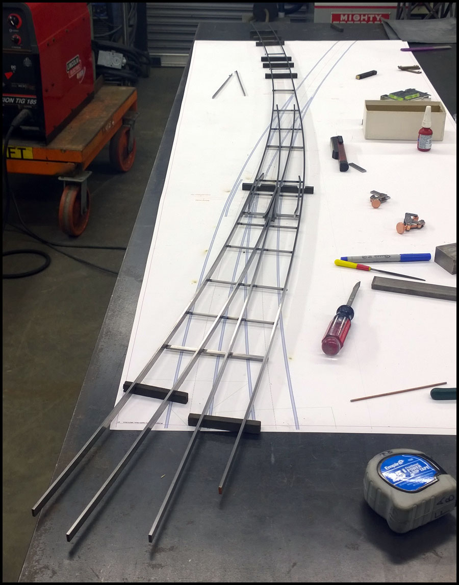
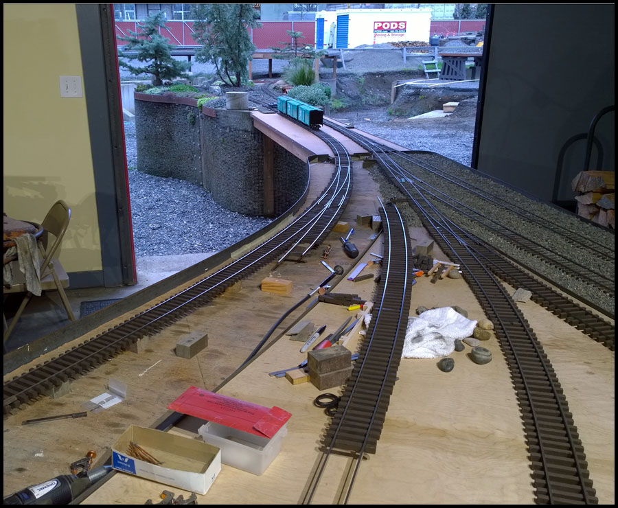
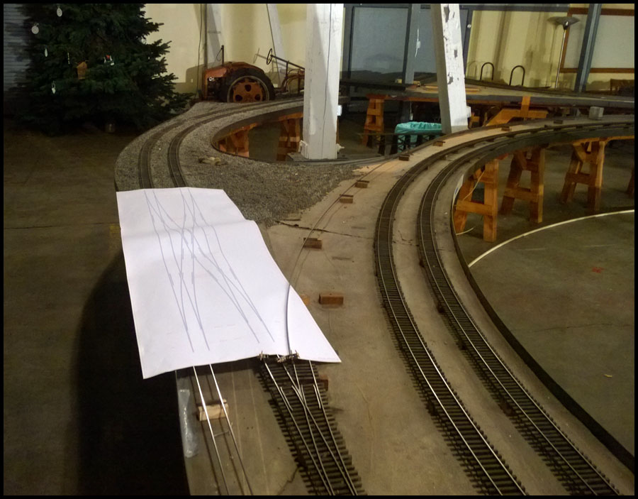
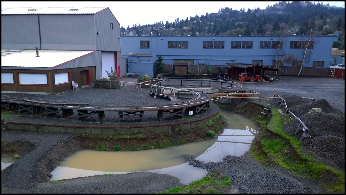
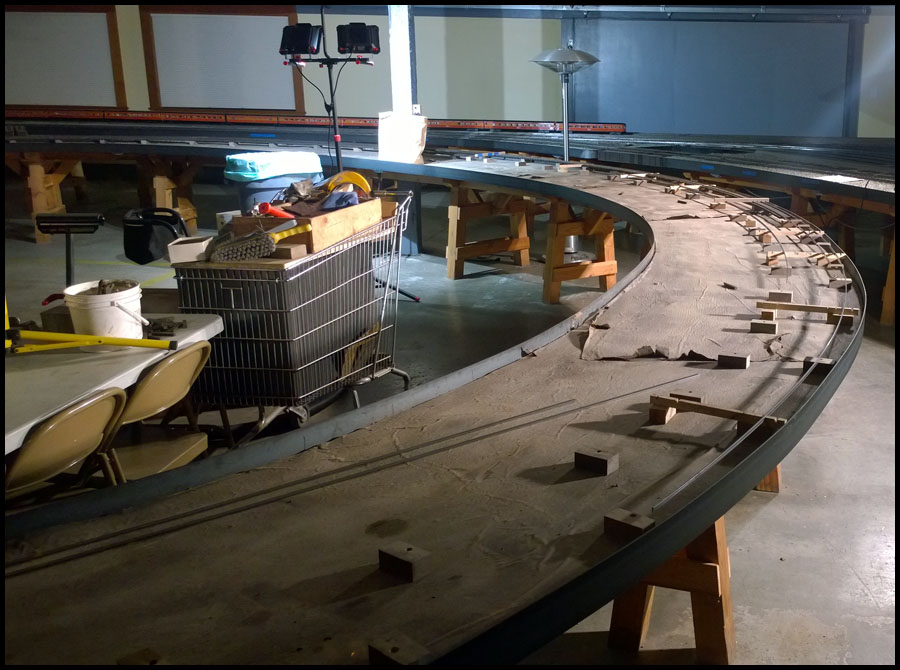
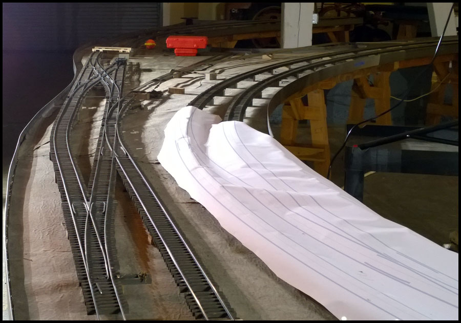
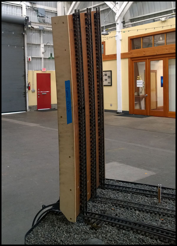
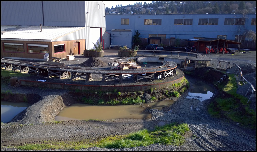
Taking a printout of the turnout and transition curves, I could lay out the entire curve, and use pieces of rail, and other things lying around to make sure of the alignment before we build anything.

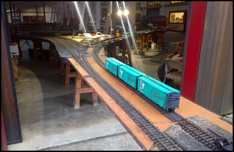
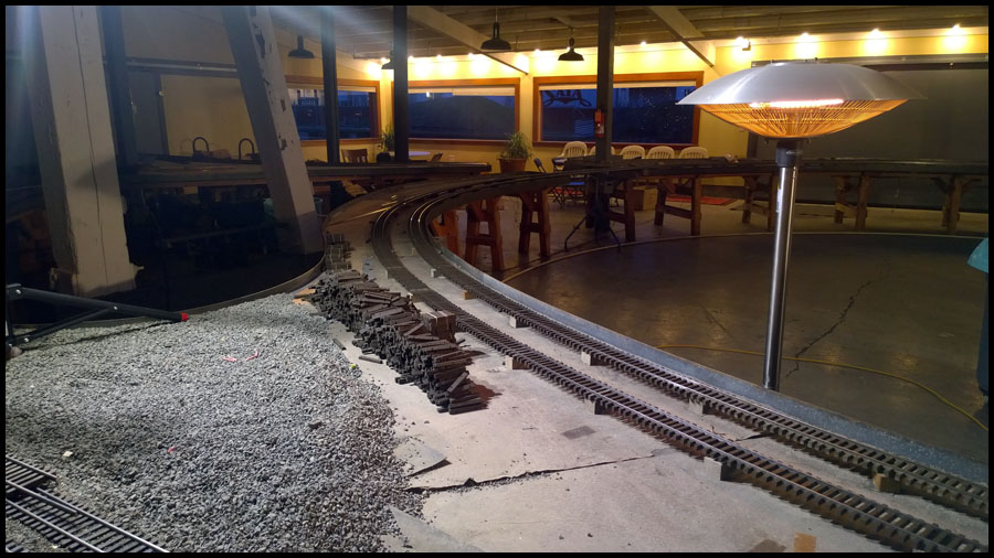
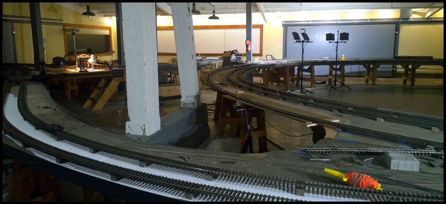
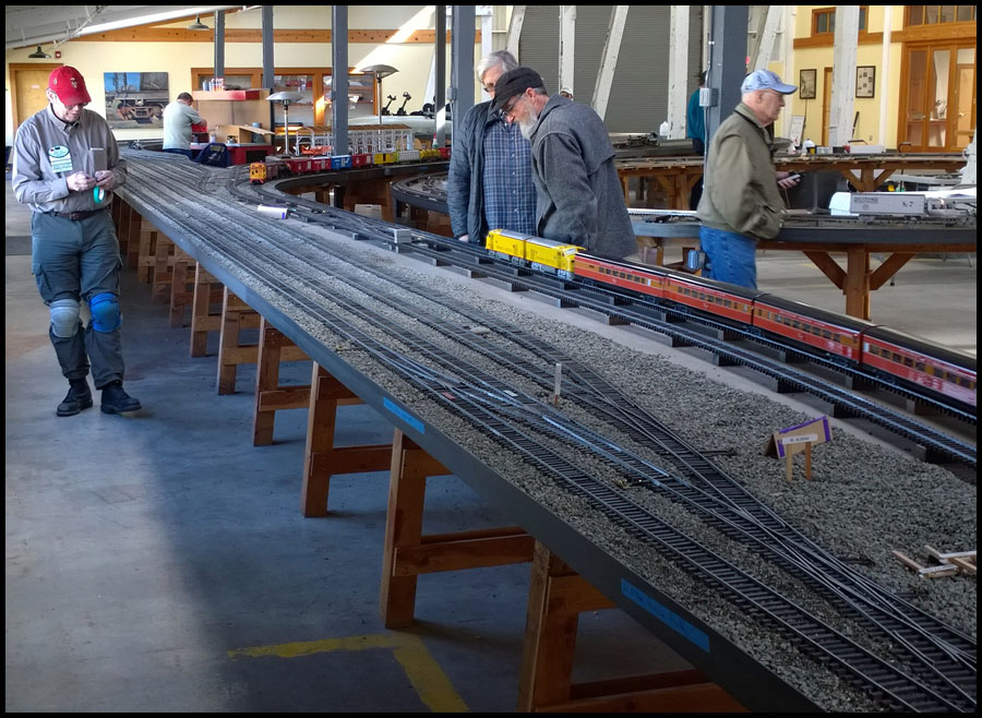
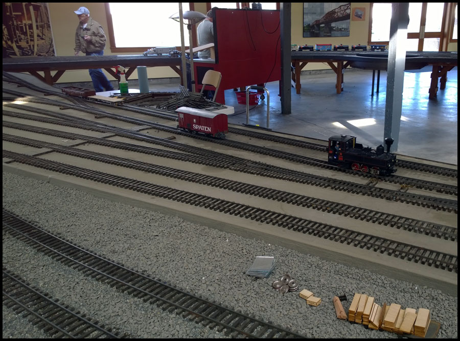
I didn’t think to get many pictures of the process. But here is a couple showing the turnout template in position and gives a rough idea how we go about the alignment. In this picture, you can
see the old curve on the other side of the bridge. This will get torn out shortly, but for now, we used it to help align the track work across the bridge.

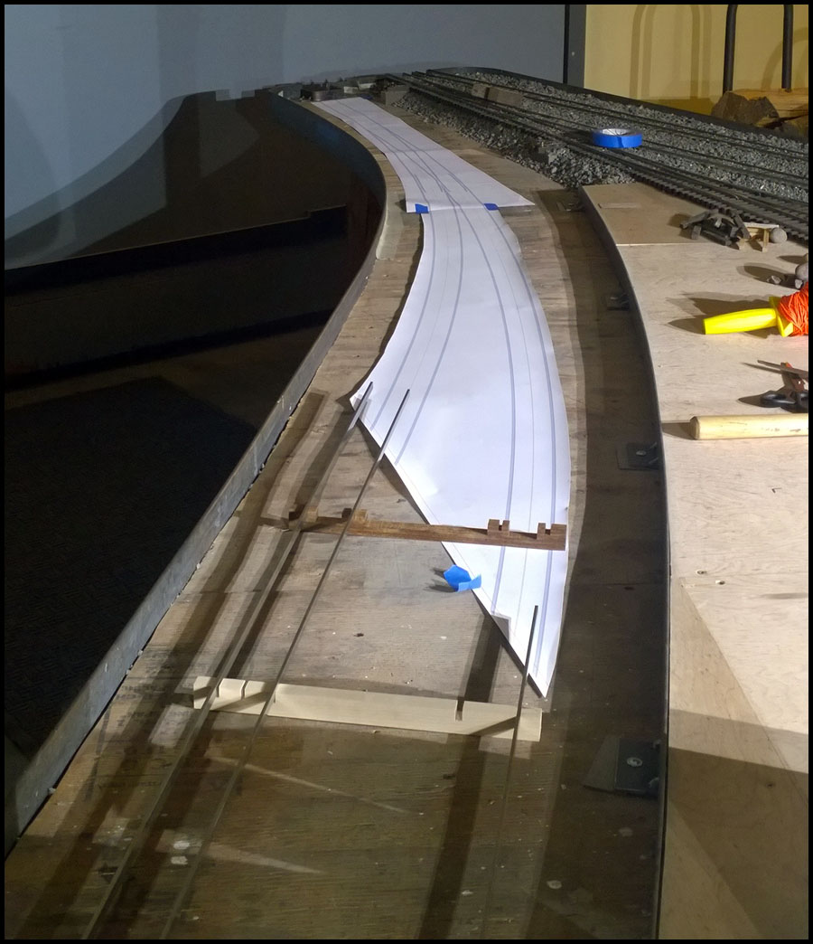
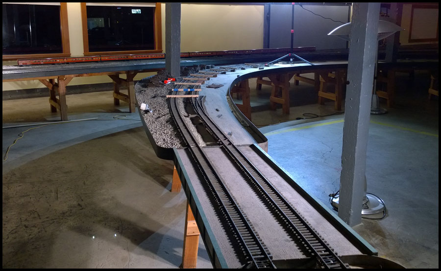
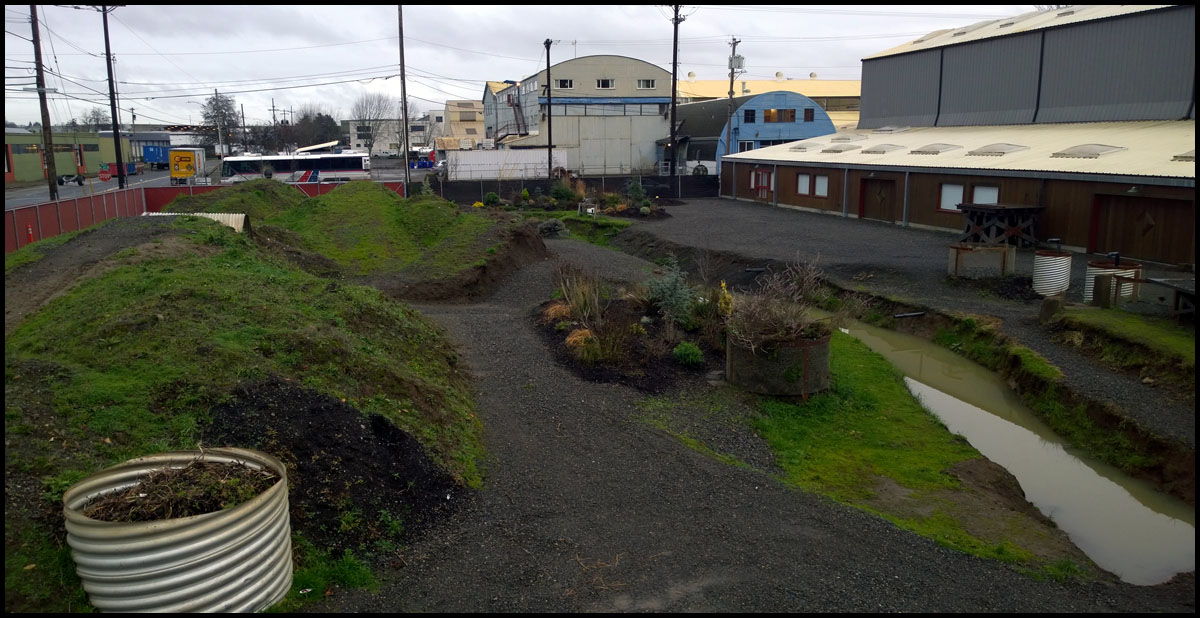
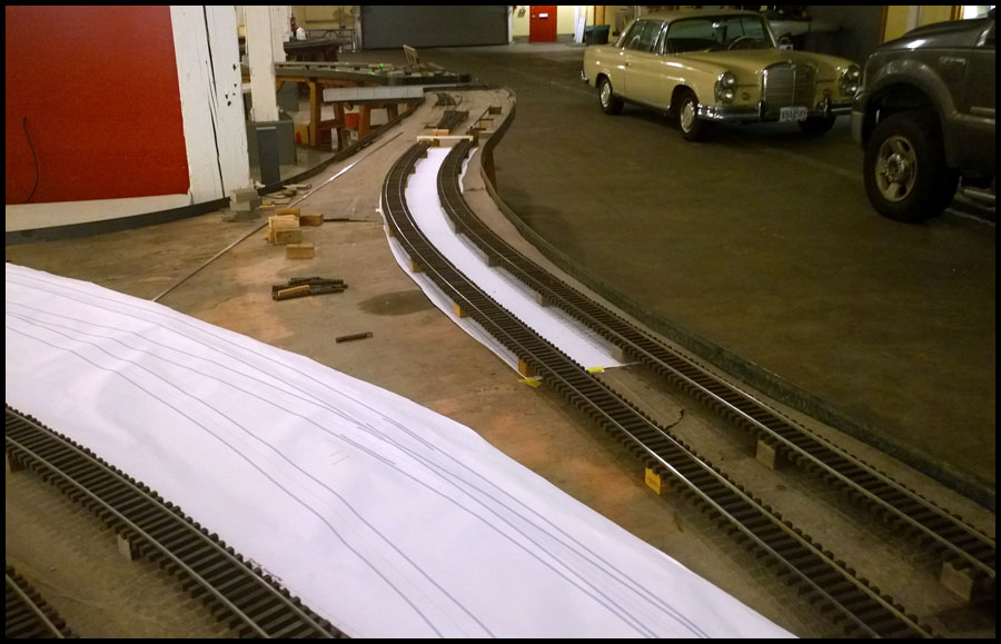
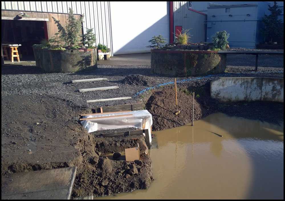
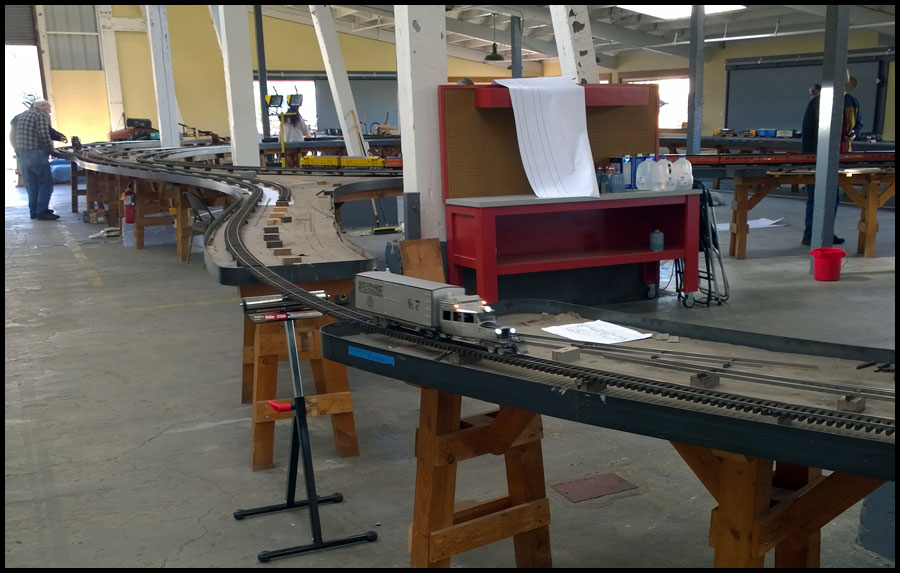
Shot from the other direction.

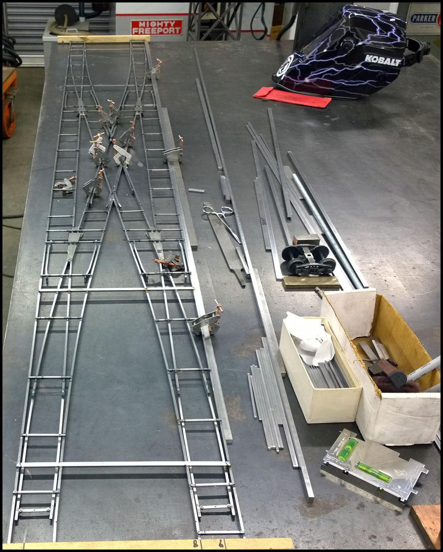
I mentioned in a previous post that I wanted to modify the frogs we use. This next picture shows why…Many years ago, when they began making
turnout parts, a fixture was made for the manual mill that would allow frogs of any angle to be produced. As I have stated, most turnouts on
the railroad currently are #7, however, many #5’s, #8’s, #10’s, and #14’s were made as well. I now make them using a different method, but
we have a stash of the old ones still around and we want to use them. The problem is that they end up very long, which is fine for a straight exit, but
will not work well on a curved turnout.

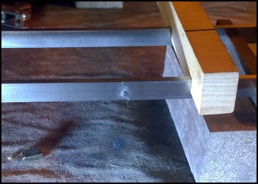
It occurred to me that there was no real reason for them to be this long other than it is easy to attach rail to the design used. I suggested we cut the
frog back to where it is exactly a 1/4" wide, (the width of to rails butted together), re-cut the slots on the surface grinder so we can bend the guard rails, and then the curved
rails would work just fine.

Here is the result…

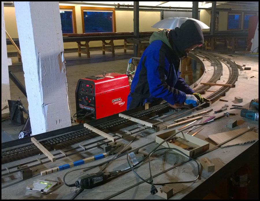
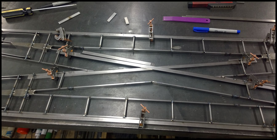
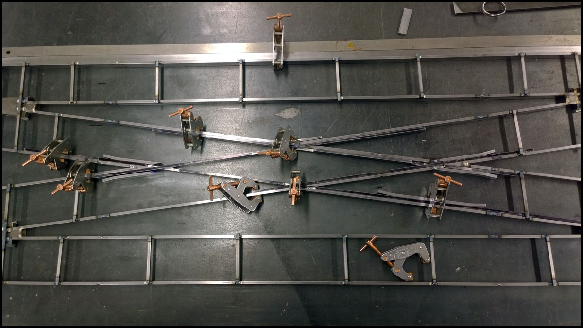
With the frog cut down and modified, Jenn was ready to start work. To build the turnout, we print out the the inverse of the Templot template
and then build the turnout upside down on top of it.

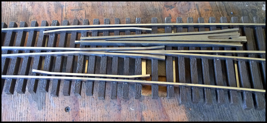
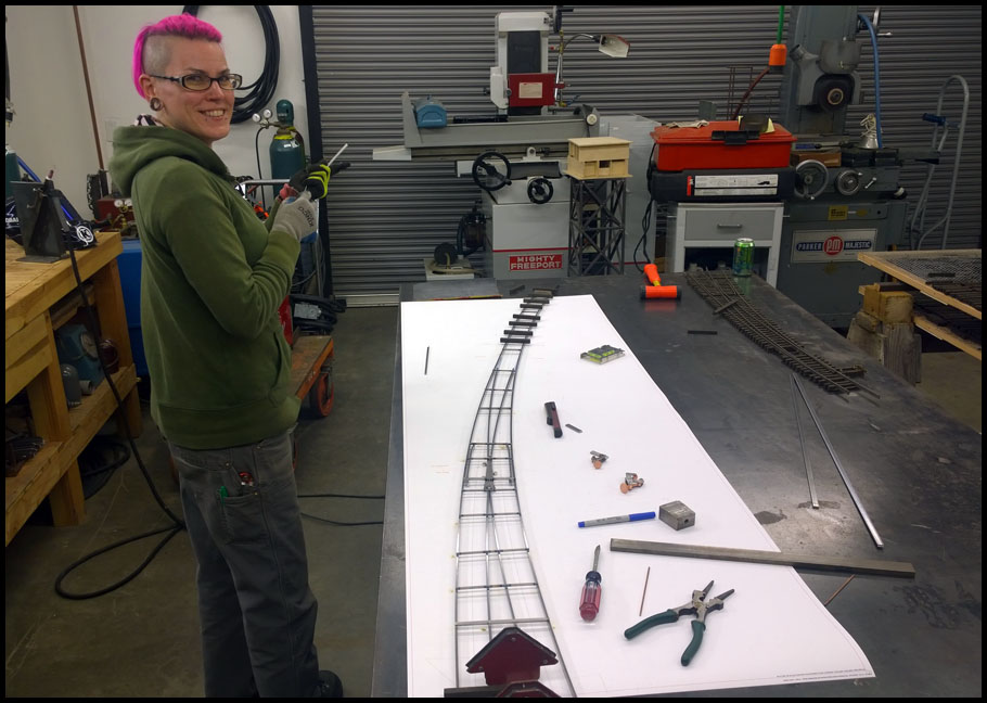
Nearly completed rail work for the turnout, and a proud Jenn showing off her work.

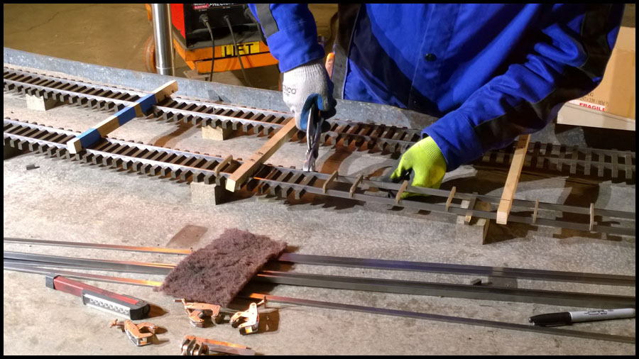
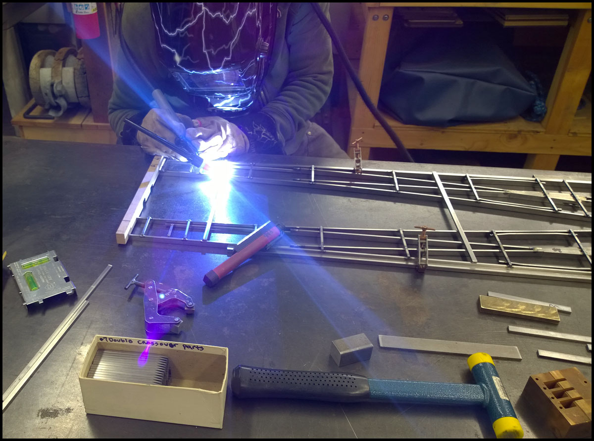
Now it is time for Jenn to make ties. This turnout is a long one, so it will take awhile…this picture shows that she is almost finished.

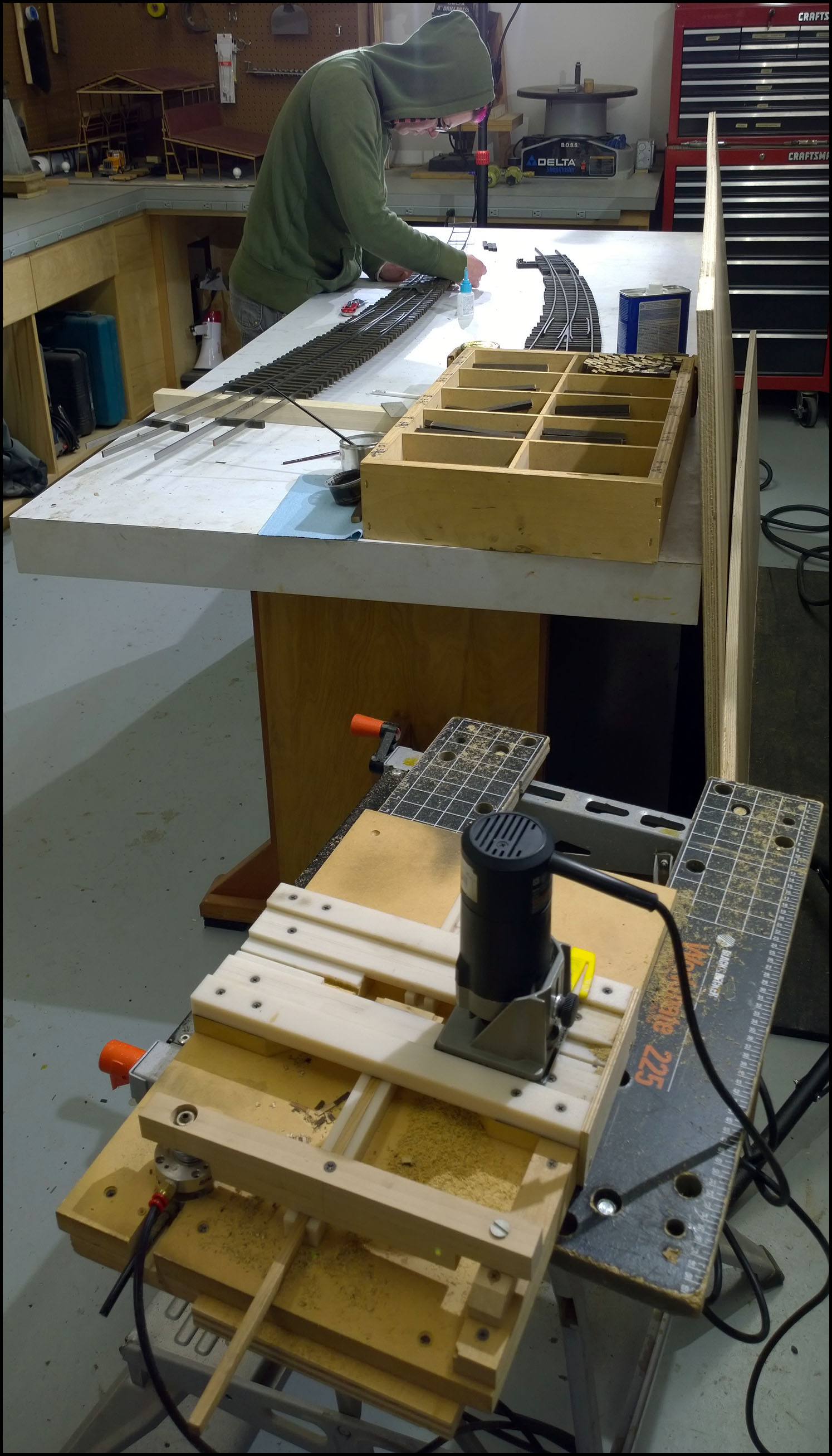
This next picture shows the clever router machine for making turnout ties. Jenn places a tie under the turnout and marks the rail positions as they cross the ties, then you can slide the tie into the slot in the plastic channel visible in the picture.
There is a long piece of unstained tie sticking out of the channel, we use this to help in locating the tie in place. The channel is hinged on the opposite side of the router. The channel swivels under the router guide, and when Jenn has it
lined up, she uses a foot peddle to activate an air solenoid that locks everything in place…then just slide the router across the tie. Sounds easy, but it takes practice and the router is loud, and the work repetitive, monotonous is the word.
Fortunately, Jenn doesn’t mind doing it so I don’t have too…

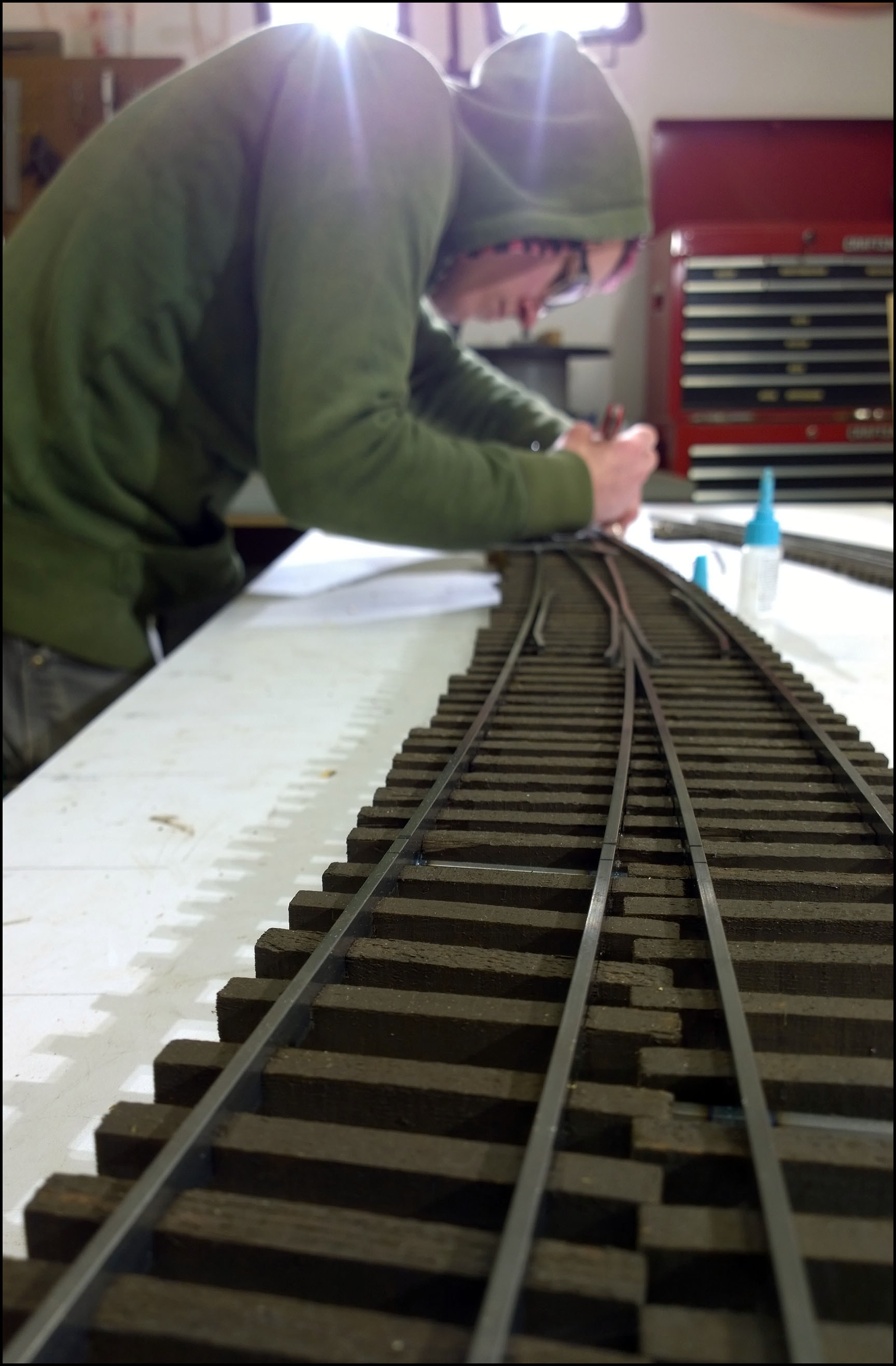
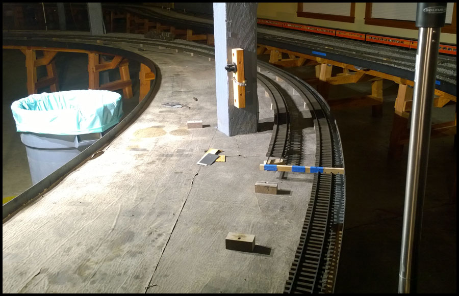
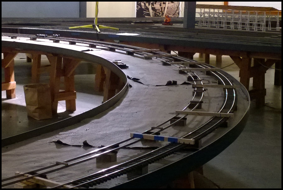
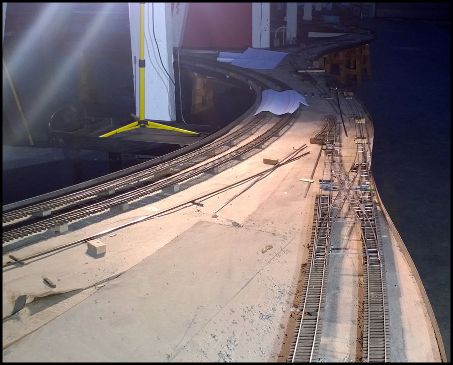
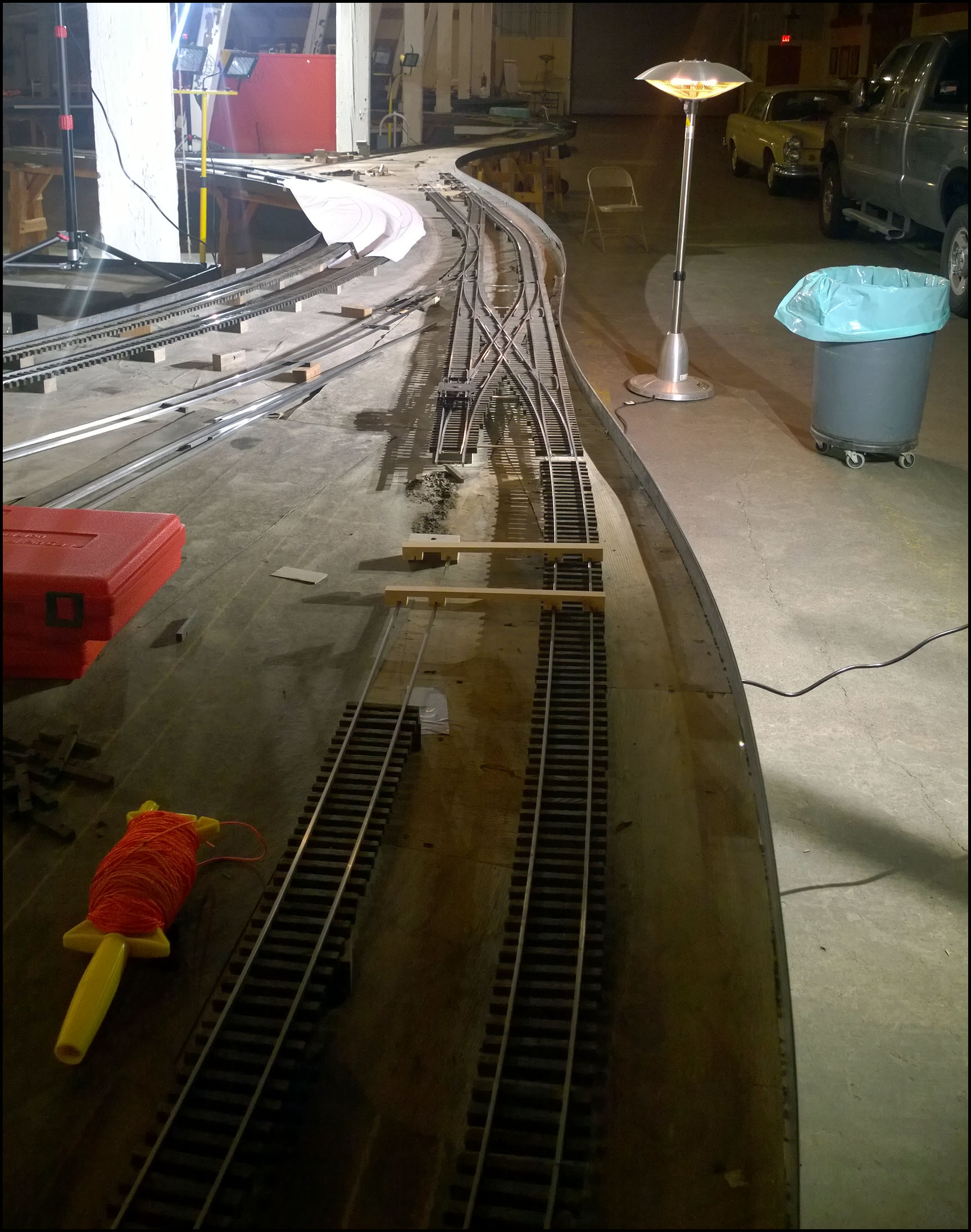
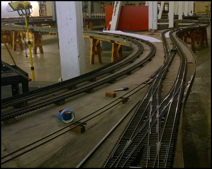
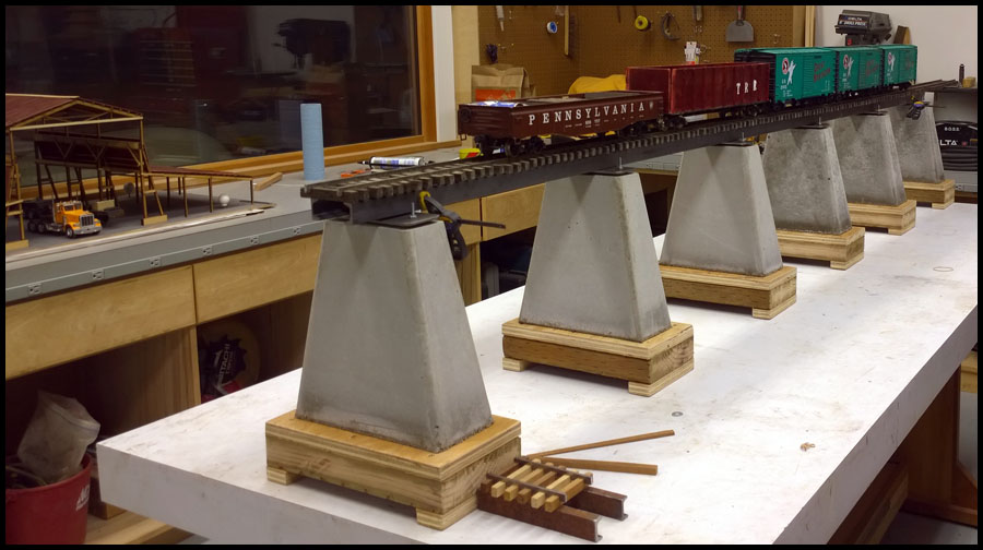
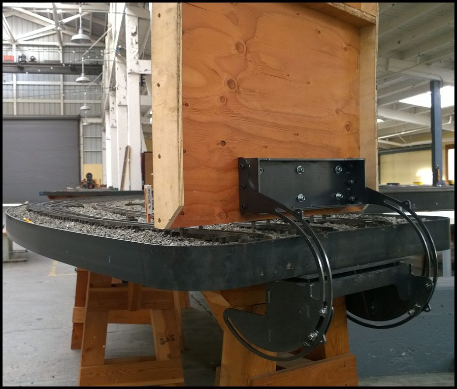
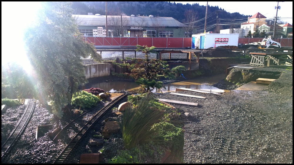
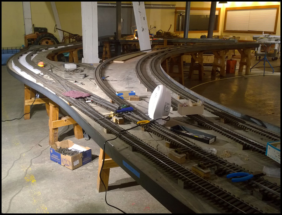
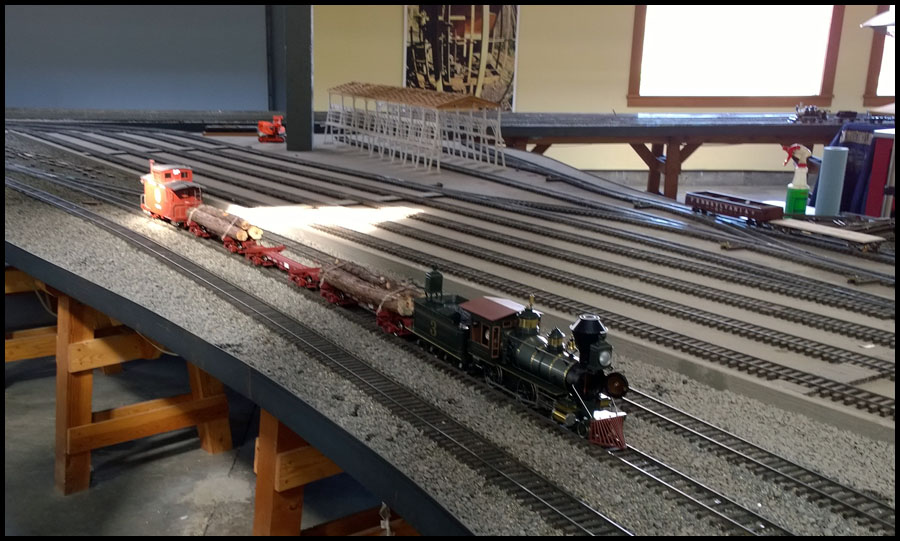
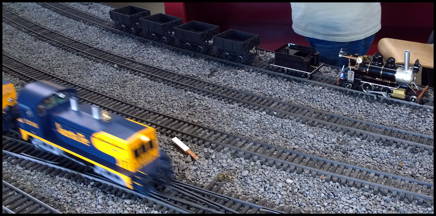
Time to install the turnout. Here is a rails eye view of the turnout in place.

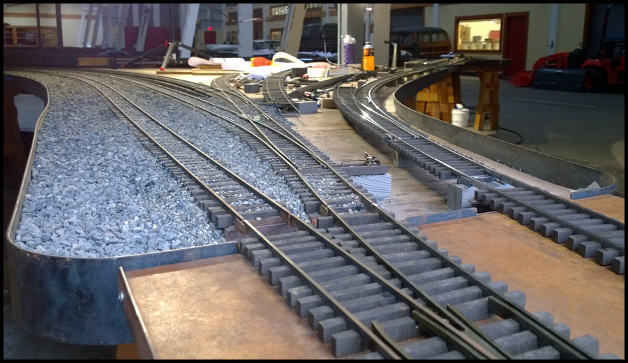
From outside looking in…sorry again about the lens flare, shopping for a new DSLR, better photography soon.

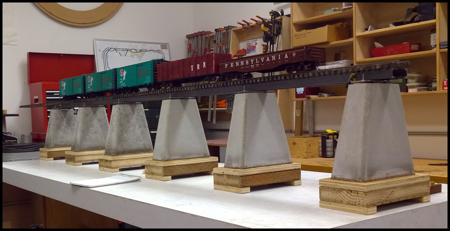
From the other direction…

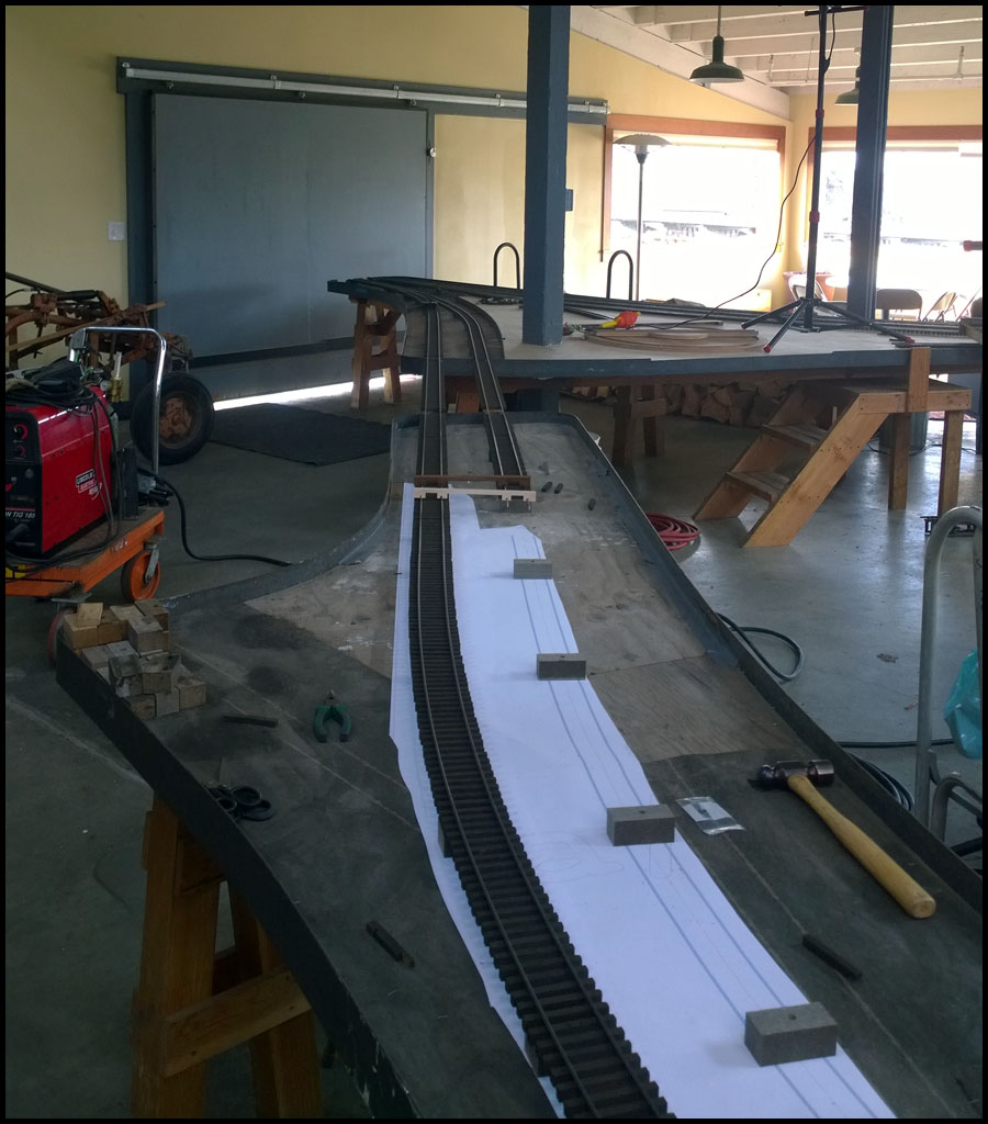
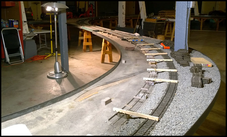
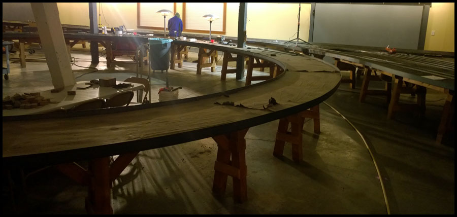
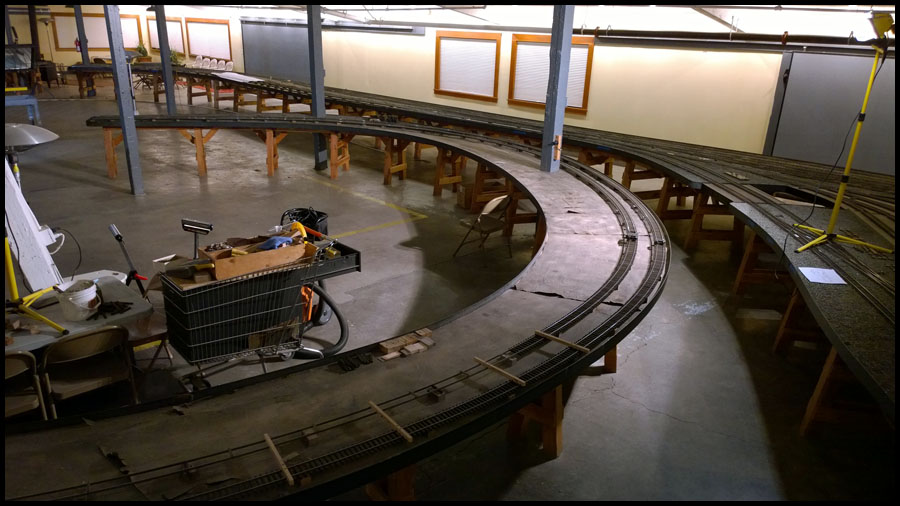
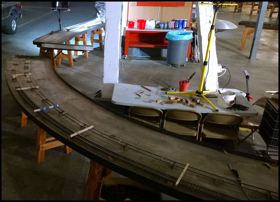
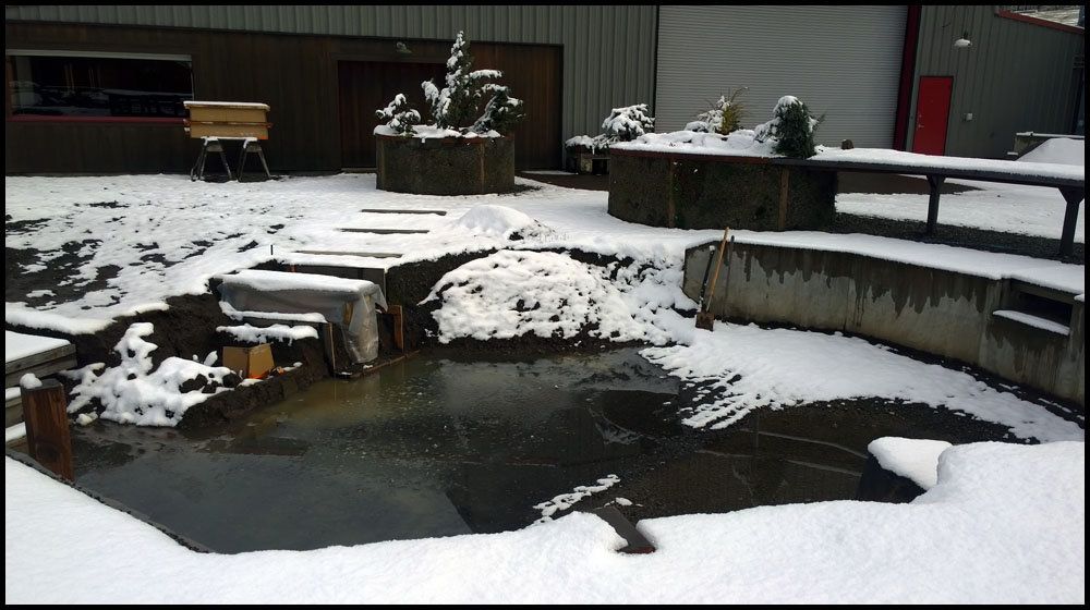
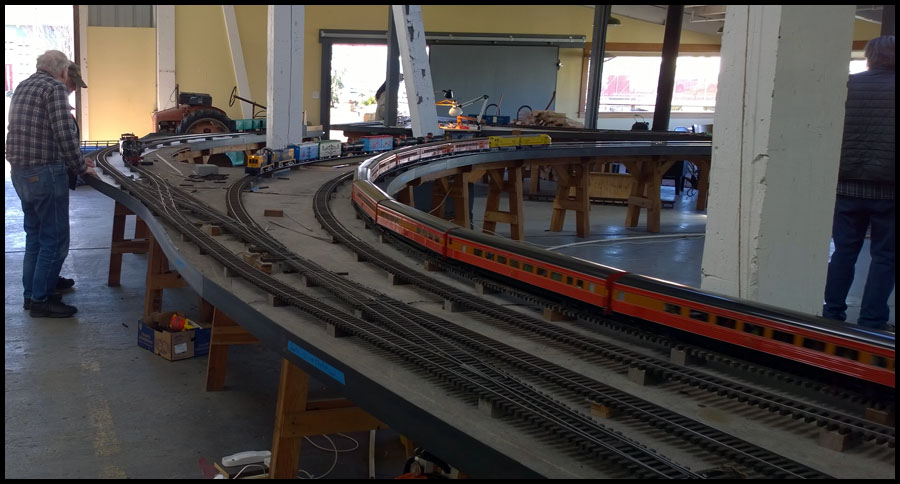
And here we are almost done. The turnout is installed, the alignment worked out nicely, so it was time to generate the transition curve and
build it to replace the existing curve and provide a short straight section before the diamond crossover.

And finally, we now have enough information to start building the layout in Templot instead of just parts and pieces. We have enough hard
locations built with Templot templates, that I can take measurements, and very closely replicate the railroad in the computer. Since this work
was completed, we have measured and built models of the existing railroad, and we are using Templot to design the middle yards. I will, of
course, document this in later posts.

Back to the railroad…

Karl

Very short on time today, we’ve been very busy at Stavers designing the new yards, figuring out how to scale satellite images so we can design over the background image in Templot,
and building the yard throat into the almost finished design for the yards.

We don’t always work on track at Stavers. Years ago I designed a vibratory table for casting concrete and Larry likes to experiment with various structures.

This winter while it was raining, Larry had Joe build some molds and try to come up with a good looking but easy to build bridge structure. This is what Joe came up with…

The first three piers were poured from some old bags of concrete and didn’t cure well for quite a while, hence the dark hue. Also they didn’t
respond well to the vibratory table.

You can see in this picture, much better results when using fresh concrete

The idea is to use channel and weld it to plates pre-drilled to fit on the studs cast into the piers. Perhaps a top plate with some detail. This is just
a prototype and may never be used, but it is one of many ideas we try out.

To make the vibratory table, I laser cut some plywood that would accept small block chevy valve springs into pockets.

Here is a view of the partially assembled table. The table top has mirrored pockets and sits on the springs. A steel table then sits over the assembly.

Here is the finished table. I have since built a safety shield around the bottom of the motor and eccentric. The eccentric is adjustable.

Must go work on the railroad some more…more progress reports on track work to come, but I haven’t edited any more pictures yet

Karl

Edit: I removed the post because I tried to post a video and it messed up the formatting of the entire post half of it wasn’t visible.

I will try again tomorrow and maybe experiment with video posting.

I tried to embed a youtube video I had uploaded, but it was only veiwable in some gigantic size which seemed to ruin the whole post.

Sorry

Karl

Ok, I spent the night and morning learning xhtml so I could make sure my embedded videos work they they did for the last 10 years?

What is with the world when they screw up something that has worked so long and is so common?

So I will attemp to post a short video that is steam trains but not what I was going to post because I need that video i n the build story.

Anyway, if this works, Jenn will be at the controls of a steam locomotive…if it doesn’t, I imagine error code…

I think I got it…back to regular posts

Karl

If it isn’t httpS, it probably won’t work here.

Post the URL, someone can figure out how to display it here.

Hi Ken:

Thanks, but I got it now. When I embed videos (not very often since I don’t do much online anymore), I don’t like all the crap youtube tries to force on you, such as logo’s, autoplay, size, and most
important, suggested videos for which I have no control.

It was just a simple matter of some studying, to find out how they changed and/or depreciated commands that control these things.

All good now, and back to editing pictures and replace my lost post from yesterday.

Thanks again

Karl

So here is a replacement post for the one I deleted…

The topic was that Larry would like to replace numerous lift out bridges with draw or lift bridges of some type, and he set me to thinking about it last summer.

After mulling over various ideas and concepts, one finally started to take root, and Larry gave permission to start modeling the prototype in Solidworks.

This is what I came up with…laser cut 3/16" steel, adjustable in every plane, robust construction, over center lift to hold bridge out of the way and let gravity
keep it open, adaptable to many of our needs on the railroad.

And here is the prototype after Jenn welded it together. It has ball bearing slides with adjustable friction from teflon thrust washers compressed
by Bellevile washers. This video shows testing of the slide friction and movement.

Installed on the railroad and attached to the lift out bridge that is normally in this spot.

It fit like a charm in the closed position. However, I tried to design it with as close a tolerance to the framework as possible…I overdid it a bit.
Like I said, it fits wonderfully, and the myriad adjustments makes it easy to install, but when open, the clearance just too tight.

The next picture shows that I need to increase the radius of the lifting slides. It did fit, but with a few issues that need addressing. I guess that
is why they call such things prototypes.

I’ve already designed a new one which is lighter, and has a larger radius. One problem we have is that even
though I can adjust the tension(friction) of the movement, and get a very nice feel for the operation, the
bridge will drop to fast on its own if someone just lets go of it…which of course, someone did while we
weren’t around and broke the bridge. Our plan was already to install a door stop piston at the bottom
of the travel…but while sitting open overnight, someone just pushed it closed, and it hit just hard enough
to pull the screws holding the track down and split the plywood forming the bridge.

Oh well…Larry wants a light weight metal bridge anyway, so I guess more time at Solidworks.

All in all, very satisfied with the results, and the new revised prototype should be here this week. Larry’s laser is 500w and we can cut 1/8" steel,
but for 3/16" we use a local laser cutter near the shop. $125.00 for one which includes steel price, plus 10-$15 in hardware. If we order a full sheet
of kits, probably less than $100 each. I think that is pretty reasonable for one off production.

We have some bridges planned for outside where we will need a different mechanism, but this should work quite well on the indoor railroad and
probably some locations outside.

Happy steaming

Karl

Hi everyone, my cold decided to play hooky and I thought I was over it, but then it came back home and assaulted me…now I am unhappily sick.

Oh well, next installment…

While we were busy inside working on building track, Joe was very busy outside prepping to add some more bridge tables for lack of a better term.

The weather was quite variable in February, and we alternated between sun, heavy rain and wind, and snow. Anyway, here is a few more pictures of
outside. First is just a picture that I thought turned out kinda cool, but it does show a few things.

In the center of the photo across the alley from Larry’s yard, is Sasquatch brewing which has great food and Beer.

Above Jenns head in the same building as Sasquatch is the Boedecker Winery.

In the blue building on the left is a giant Zinc plating company that dips light poles and other infrastructure, and provides industrial clanging noises
to the ambiance at Stavers. Also, the railroad still delivers rail cars to businesses near Stavers, so now and then a locomotive strolls right by the
back of Larry’s yard. There is yet another brewery across from the winery to the northwest.

The two tanks in the left center are part of a water collection system that is fed from all the runoff of the north side of the building, which then fill up
and feed the pond. There will be more of these in the future.

In the next picture is the east end of the pond and gardens. The wind storm the night before tried to tear off the fabric tarp along the last
unimproved section of fencing. Jenn and I repaired the fencing after this picture.

The two red doors on the side of Larry’s building will be under a large covered patio to be built along the north side of the building. Final plans are
done and the construction crew will be showing up after the April steam up to begin work. I believe this part of the fence will also be replaced with a
really nice gate and small ticket booth type of entrance, but I don’t know the final plans for certain.

I scaled a satellite photo of Larry’s yard and have begun planning the track layout in the outdoor space. I’ll show a picture of that another time, but for now
you can see that Joe removed the PVC pipe and poured some concrete footings into molds for the new bridge table.

Heavy rains filled the pond almost to the spill way of the dam. Here is a better picture of the concrete footings. I don’t envy some of the conditions Joe works
in…on the other hand, we freeze near to death working on track sometimes. Still, wouldn’t trade it for anything.

The next shot I just thought was kinda cool. In the top edge of the picture, you can see the snow line in the west hills was at about 250ft. Makes the warehouse
cold and damp at night. Freezing level kept going up and down that week, and we got varying amounts of snow around the area all week.

You can also see the other brewery (Pyramid Brewing), in the tall tan building on the right top corner of the picture.

Sure enough, the snow level came down overnight. Fortunately, not to much so we could get there without much trouble. Would have been a fun day to play
with a snow plow. Against the building, you can see the molds Joe uses to pour the concrete bridge footers.

Out of time, I have been editing many more pictures of track work, a few of first Tuesday, and some shots of other tools we use. But I must go work on the
railroad. Since the new shorter frogs have worked out so nice, it has also allowed us to completely change the way we make them that should save
significant time, and allow us to create any angle frog easily in two operations instead of six.

The last few days I have spent much time learning the new cam system that comes preinstalled in Solidworks. Larry and I don’t like Mastercam and want
to shift away from using it for the new system. So far pretty good success, I am by no means a good user with only a few hours invested, but thankfully,
having used a few cam systems allows me to adapt relatively pain free to the new one. At this time, I have created what look to be good toolpaths
for #7 frogs, making two at a time on Larry’s Haas mill.

Happy steaming

Karl

Hello:

This cold turned out to be quite a bad one, I’m darn near coughing up a lung every few minutes last couple days. Oh well.

On the Sunday before first Tuesday, the weather was really nice, so Jenn and I took our first day off in a while that wasn’t
full of chores. We ran up to Ridgefield Wa., a small town on the Columbia river about 20-25 miles North of Portland, by
following the BNSF mainline and had an annoyingly expensive lunch at a local place. However, a couple trains sped through
so it wasn’t all bad. It was still relatively early, so we decided to head east out the Gorge to one of our favorite spots on
the Columbia.

This spot is about 30 miles east of our home on the Washington side of the river. The BNSF mainline has a bridge to cross
an inlet to a lake formed by the built up road bed of the railroad. Anyway, you can easily get down under the bridge and out
onto a rocky outcropping that people use to fish. From there you have a beautiful view of the sunset, the Columbia River Gorge,
and the UP mainline running for miles along the Oregon side right across the river. About 20 feet behind and above you is the
BNSF mainline just exiting the bridge.

Just a great place to hang out, and there are trains too.

On Monday, we had a lot to do so that a full loop would be available for first Tuesday. First up was to complete a temporary loop on the inside.
We just quickly welded up some track that will be torn out later when we redesign the interchange on the other side of the railroad.

Although I have designed a new switch stand mechanism, it would not be ready for first Tuesday, so Jenn got to work installing the ones we
have on all the new track work.

First Tuesday arrived and we had everything working, at least enough for good times. Here the on coming train is using the temporary indoor
loop branch line.

Next is a picture of the dispatchers desk. I took these pictures when things were winding down for the day and quite a few had left already.
There seems to be a growing interest in first Tuesday operations, with a few new people showing up each month.

The dispatch system is pretty low tech at this time. A telephone system is used. Hardwired phones are located around the railroad, upon arrival
the engineer should call dispatch for instructions.

For those who have never met Larry, that’s him with the beard and black cap next to the locomotives.

One of these days, I’ll remember to have Jenn take a picture of me working on something, but I’m not much to look at…

Here is a picture of the temporary line connecting the soon to be removed loop. I must have messed up a setting on the camera, because most
of the pictures seem to have affects from a slow shutter speed. Can’t wait for a real camera again but haven’t had time to acquire one.

One of the steamers that showed up to participate.

Another steamer getting ready, as my slow shutter makes a prototypically slow train look like a high speed runaway.

Finally, a European prototype in the narrow gauge yards.

Anyway, I have to go suffer some more, I mean work on the railroad. Next installment will be the new yard throat, and some pictures of the
tie making machine.

Thanks

karl

Karl,

Good to see the progress! Really great design for the lift bridges.

Are you going to double track the existing outside loop?

Also, I have a spare Canon digital SLR body I probably won’t ever use again. It’s a Canon Rebel XT 350D, 8Mpixels. You would have to get a lens for it. But it’s yours if you want it. Contact me offline if you want me to send it up.

Rob Lenicheck