Large Scale Central

V&T Derrick 50

Well, I’d rather go that direction any day than put a Thomas face on it.

(https://www.largescalecentral.com/externals/tinymce/plugins/emoticons/img/smiley-foot-in-mouth.gif)(https://www.largescalecentral.com/externals/tinymce/plugins/emoticons/img/smiley-laughing.gif)

[edited to add a smiley…]

Not sure where I was going with my last post, but it was a work travel half-week and those always leave me in a half la-la state. Which would be a full “la,” come to think of it. Anyway, yay, back home now, and I got a half day yesterday and most of today to work on this.

The big deal yesterday was getting the brake line piping in, which involved bending, soldering and epoxying. After that I was able to bolt up the underside mast base. This pic gives an idea of how many screws were needed.
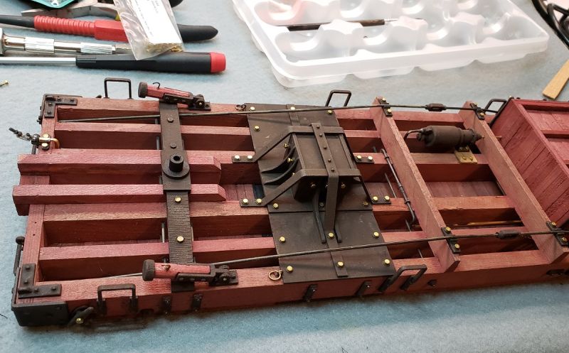
I wanted to post the above pic before it all got blackened. I like the shiny bits, so it’s always a bit of a downer when blackening. Whatever; that’s what therapy’s for. And here’s the underside, all finished.

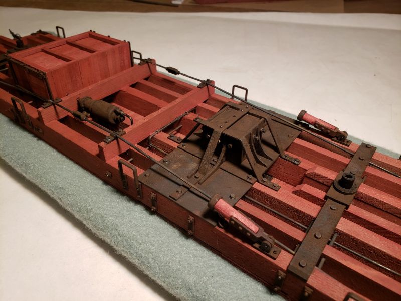
BTW, I had a nice bit of success with the u-bolts that secure the transverse piping as it crosses the sills. First, I held the pipe against the beam and pin-vise-drilled a 1/32" hole on either side. Then I bent a bit of #22 solid copper wire (without insulation) around a piece of 1/16" rod, with legs ~1/4" long. I tapped this into the holes with a jeweler’s hammer, and it’s nice and secure.

The below pic also shows the mast’s jacking bolts, 3 on each side.
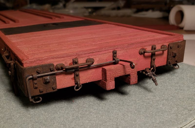
This derrick had 4 rigging rings at each end, and here they are. Lots of cleanup to do, man, these hi-res shots are far better than my eyesight! I’m reminded why I complained about my CA skills last week… I’m considering fixing the gloobers with a scalpel and more stain. Or by just not including closeups in my October presentation. (https://www.largescalecentral.com/externals/tinymce/plugins/emoticons/img/smiley-foot-in-mouth.gif)
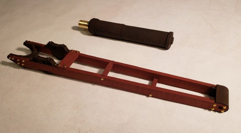
So the car body assembly is done, and now I’m moving into the derrick itself. With the boom’s wood being assembled (via jig) already, I began with installing the 3d printed base yoke casting. And I was pleased & surprised to see that the fit was perfect, in spite of the compound angle. The jig-drilled holes lined up with the 3dp holes on the base yoke and the head casting, and the winch frames fitted up with minimal filing. So after being ready for catastrophe, I was really thrilled.
Lots more to do on the winch and rigging, and then come the five trucks.

Thanks for hanging with me on this,

===>Cliffy

Mein Gott, I love your work, Cliff! I may need to join you for therapy, as I like the shiny bits too. My only complaint is that you don’t spend enough time on this, so your audience is left wanting.

Cliff,

The above video is about where I am at with builds currently but yours it’s looking great !

As for the CA …in my findings it’s gonna bleed on the wood no matter what. A contact adhesive is the way to go on that end IMO . Think I shared my favorite contact adhesive with you before but opinions will vary on the best.

As always excellent work!

Rooz

Thanks Jim, haha! Well, I plan to spend another day on this today, and don’t have more travel on the horizon, so hopefully this will go more quickly! :wink:

Rooster, great video! So you think I can get enough contact adhesive on a small 1/16 plastic pin (going into the hole) and / or on the back of a mounting plate (say, 1/4" x 1/8") and have it hold? And I forget, which product do you use? Thanks!

Cliff, each update just brings more detail and that brings more awe. Your attention to the tiniest details shout realism. Great work.

Cliff Jennings said:

Not sure where I was going with my last post, but it was a work travel half-week and those always leave me in a half la-la state. Which would be a full “la,” come to think of it. Anyway, yay, back home now, and I got a half day yesterday and most of today to work on this.

The big deal yesterday was getting the brake line piping in, which involved bending, soldering and epoxying. After that I was able to bolt up the underside mast base. This pic gives an idea of how many screws were needed.

Cliff love your very detailed work, can you maybe explain about the small bolts your are using like type, size and where you get them?

I wanted to post the above pic before it all got blackened. I like the shiny bits, so it’s always a bit of a downer when blackening. Whatever; that’s what therapy’s for. And here’s the underside, all finished.

BTW, I had a nice bit of success with the u-bolts that secure the transverse piping as it crosses the sills. First, I held the pipe against the beam and pin-vise-drilled a 1/32" hole on either side. Then I bent a bit of #22 solid copper wire (without insulation) around a piece of 1/16" rod, with legs ~1/4" long. I tapped this into the holes with a jeweler’s hammer, and it’s nice and secure.

The below pic also shows the mast’s jacking bolts, 3 on each side.

This derrick had 4 rigging rings at each end, and here they are. Lots of cleanup to do, man, these hi-res shots are far better than my eyesight! I’m reminded why I complained about my CA skills last week… I’m considering fixing the gloobers with a scalpel and more stain. Or by just not including closeups in my October presentation. (https://www.largescalecentral.com/externals/tinymce/plugins/emoticons/img/smiley-foot-in-mouth.gif)

So the car body assembly is done, and now I’m moving into the derrick itself. With the boom’s wood being assembled (via jig) already, I began with installing the 3d printed base yoke casting. And I was pleased & surprised to see that the fit was perfect, in spite of the compound angle. The jig-drilled holes lined up with the 3dp holes on the base yoke and the head casting, and the winch frames fitted up with minimal filing. So after being ready for catastrophe, I was really thrilled.

Lots more to do on the winch and rigging, and then come the five trucks.

Thanks for hanging with me on this,

===>Cliffy

Thanks guys! And since I had a sort of unexpectedly free Saturday, I’ve been working on the derrick proper, and and glad to say that area is almost done.

The crank shaft was tough, because there are four stop collars 2 gears on it. When the crank shaft’s collars are centered on either side of the lock in the center (the thing on hinges with a little handle), the winch is in neutral / free-running. When shoved to the left (away from you, as shown in the pic below) the near spur gear acts directly on the bull gear & drum. This is for lighter / quicker lifts. If the crank shaft is brought toward the camera / to the right, the upper secondary shaft is engaged on both sides, giving much better lift capability.

Anyway, the first time I put the crank shaft together, nothing worked right. So I cut it out and redid it, this time having thought the assembly order through better. I was glad the CA worked great on the brass, because I didn’t want to risk soldering the brass and melting the plastic parts.

The center lock and both crank handle hubs were printed in brass by Shapeways for about 12 bucks. I was impressed in their detail, much better than the “professional plastic” everywhere else.

For shipping, the mast pugs into the car, and the boom drops onto the mast. The mast doesn’t rotate, just the boom. Two rollers at the bottom of the boom’s base casting roll on the thicker band at the bottom of the mast.

I’m glad to report that the boom rotates smoothly, the mechanism works, and all the sheaves (boom and hook) spin freely. So the next step is rigging the cable and also the boom’s transport stays, which I hope to get to tomorrow.

Thanks for your interest, and if you want me to elaborate on something more just tell me.

===>Cliffy

BTW, here’s the old gal now. Her boom was lifted off the mast a few years back, probably to reduce the weight before her back broke – which it did, as you can see.

if you don’t get comments from some of us, it is, because we are speechless.

yea, what he said…(https://www.largescalecentral.com/externals/tinymce/plugins/emoticons/img/smiley-wink.gif)

Put the crack pipe down Cliff !

Are you going to build a replica of it in its current state, as contrast to its “new” state as you are currently building, for showing in your display? If not, what the heck are you spending your time on? Sheesh!

Great work as usual, The Cliff!

Korm Kormsen said:

if you don’t get comments from some of us, it is, because we are speechless.

Thanks Korm, I’m glad you like it!!

Cliff Jennings said:

Thanks guys! And since I had a sort of unexpectedly free Saturday, I’ve been working on the derrick proper, and and glad to say that area is almost done.

The crank shaft was tough, because there are four stop collars 2 gears on it. When the crank shaft’s collars are centered on either side of the lock in the center (the thing on hinges with a little handle), the winch is in neutral / free-running. When shoved to the left (away from you, as shown in the pic below) the near spur gear acts directly on the bull gear & drum. This is for lighter / quicker lifts. If the crank shaft is brought toward the camera / to the right, the upper secondary shaft is engaged on both sides, giving much better lift capability.

Anyway, the first time I put the crank shaft together, nothing worked right. So I cut it out and redid it, this time having thought the assembly order through better. I was glad the CA worked great on the brass, because I didn’t want to risk soldering the brass and melting the plastic parts.

The center lock and both crank handle hubs were printed in brass by Shapeways for about 12 bucks. I was impressed in their detail, much better than the “professional plastic” everywhere else.

For shipping, the mast pugs into the car, and the boom drops onto the mast. The mast doesn’t rotate, just the boom. Two rollers at the bottom of the boom’s base casting roll on the thicker band at the bottom of the mast.

I’m glad to report that the boom rotates smoothly, the mechanism works, and all the sheaves (boom and hook) spin freely. So the next step is rigging the cable and also the boom’s transport stays, which I hope to get to tomorrow.

Thanks for your interest, and if you want me to elaborate on something more just tell me.

===>Cliffy

Cliff, beautiful piece of work, I would like to know how you rust your parts and hex head bolts and/or screw type/size and where to get, thanks, Bill

The Detail is very impressive, Looks awesome

Dennis

Looking superb as always Cliffy

Today I was able to get to the rigging. There are 5 sheaves and 1 drum involved, and the thread kept misbehaving. This fishing weight helped a lot.

Here’s the cable on the drum. That bull gear shouldn’t be so near the deck, so I need to adjust a couple of things.

The brass stays in the foreground are what kept the boom stationary during transit. They, like the belaying ring for the derrick hook, needed their various deck fittings added.

Last thing today was finishing up the coupler drawbar pockets. This is set up for the standard gauge static display in October. But after that the coupler will be taken out and blanked off for g-gauge operation.

This brings me to the point of building the trucks, yay! Hopefully next weekend I’ll make some progress there.

Thanks for your interest! And when I don’t say much in response to your often very generous comments, it’s just that I don’t know what to say but a very heartfelt THANKS!!

===>Cliffy

This is a good pace for updates, Cliff. Thanks for changing your entire life around to satisfy my whims :-).

Looking awesome. There’s something about rigging and pulleys that is so cool. Boomer and Rooster would say “shadows” are what it’s all about. You have a lot of shadows on this puppy…