Large Scale Central

Sutro Pneumo Loco

Not really an apples to apples comparison. Scuba tanks are pressurized to very high pressure. I don’t think the compressed air locos are anywhere near that. I think they are more akin to the pressure in your air compressor in the garage. They would have a similar working pressure as a steam loco. Only with air and not steam.

A scuba tank needs a lot of air in a very small space. Where as a compressed air loco can have a much larger tank at lower pressure.

Yep, could be quite dangerous, especially with older riveted iron vessels. If a failure happens, the air (acting like a spring) wants to keep tearing and widening the opening. That’s why pressure vessel testing is done with water (hydrotesting), because it can’t be practically compressed and act like that.

Even at 200 PSI the force can be impressive. The end flange, for example, has about a 16" diameter which is exposed to internal pressure. That’s 804 sq inches x 200 lbs = 80 tons wanting to blow that hatch off. 120 tons when they tested this loco to 300 psi. Sorta scary!

With those stats I wouldn’t let that thing in my house :sunglasses:

As hard as it is I’m going to ignore this …at least for now anyway!

I wasn’t aware I owed you but I know dad still owes me $20. However what help are you seeking (the rivets?)

I guess I wrote that in response to the 6-toed Pete gig, in view of the 2 rooster crack pipes I posted for you.

:grin:

1 Like

Not necessarily as there are other possibilities. Personally from what little research I have done on the fireless and compressed air locos/trams (which is all your fault BTW)
I feel it’s entirely possible that it’s just a jacket covering the real internals of air reservoir “s” ? The key word is “S” just like HTTP +S = another thread that has been covered back in the day.

I’m seeing some Arthur Parsey influence (British, 1791–1857) with the L&Y loco…

Hell, who knows Old Man Parsey may have been drinking buddies with the boys at the local pub “back in the day in the hood”. The old bastard knew he was gonna crap the bed and shared his information in the local pub with the boy/boys and told them to carry on!

http://douglas-self.com/MUSEUM/LOCOLOCO/airloco/airloco.htm#pars

Just so others can get to where I’m at right now Cliff.

https://www.tramwayinfo.com/Tramframe.htm?https://www.tramwayinfo.com/tramways/Articles/Compair6.htm

Hoping Bruce isn’t reading this on his Ipad or he’s gonna be in the bathroom for an hour!

Jean told on him at your house last year while discussing your man bathroom with the killer magazine rack!

Shut up Rooster

Amtrak Yoda

The fluting on the Parsey loco is troubling and could there have been fluting on the L&Y design. The SR-71 black bird knows not if… “the truth it is”!

I had a real world experience with this. As a water guy I deal with testing water lines. We had a 12 inch blind flange that was not physically restrained. It was meant to be removable so the idea was to hold the blind flange in place with mass, a concrete block backed by yards and yards of dirt. The Forman on the job turned on the water without the concrete or earth to hold the flange in place. 12 inch pipe with 70 pounds per square inch developed an astronomical amount of pressure. The flange came off and shattered a workers knee and then filled the ditch with 1500 gallons a minute of water. Scary to say the least. While not explosive like a scuba tank and 3000psi, volume and pressure make for a scary experience

I know…I watch my son eat dinner!

Indeed! I used to design hyperbaric chambers, and some of the failure pics I was shown were disturbing. Like an improperly dogged hatch blowing through a poured concrete wall.

Here’s some analogous vids about compressors:

Thanks to Bob’s prints, and discovery of a number of things needing fixing, I’ve printed a much better version. Thanks Bob!! Improvements:

  • Thickening of several things, like roof, roof angles, floor board, handles
  • Doubled the end head rivets (hey, safety first! don’t want them to blow!)
  • Increased the rez to get rid of those facets on the tank
  • Added back in the reversing handle (above the pen point), not sure how that got dropped
  • Things too mundane to mention

New print is in back.

So, Cliff was very generous and sent me his first test print (the one on the bottom above). Friday I spent the evening carefully removing the supports. Holy moly, that is a crazy amount of work! Yesterday I repaired what I broke removing supports. I had snapped both main rods, broke off the light in the cab, shattered the roof, and more.

The roof was covered with a thin ABS sheet glued to what was left of the old roof between the rails. The rods were pieced back together and the cab (reverse) lamp put back in place as well as a few other things tacked back where they belonged. I did not attempt to repair the control handles I broke off. No one but Cliff would notice them missing.

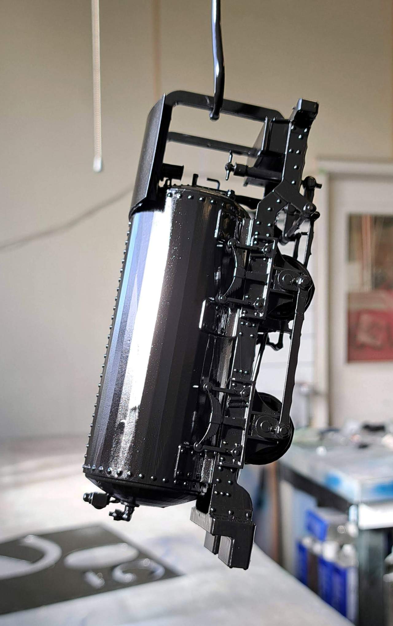
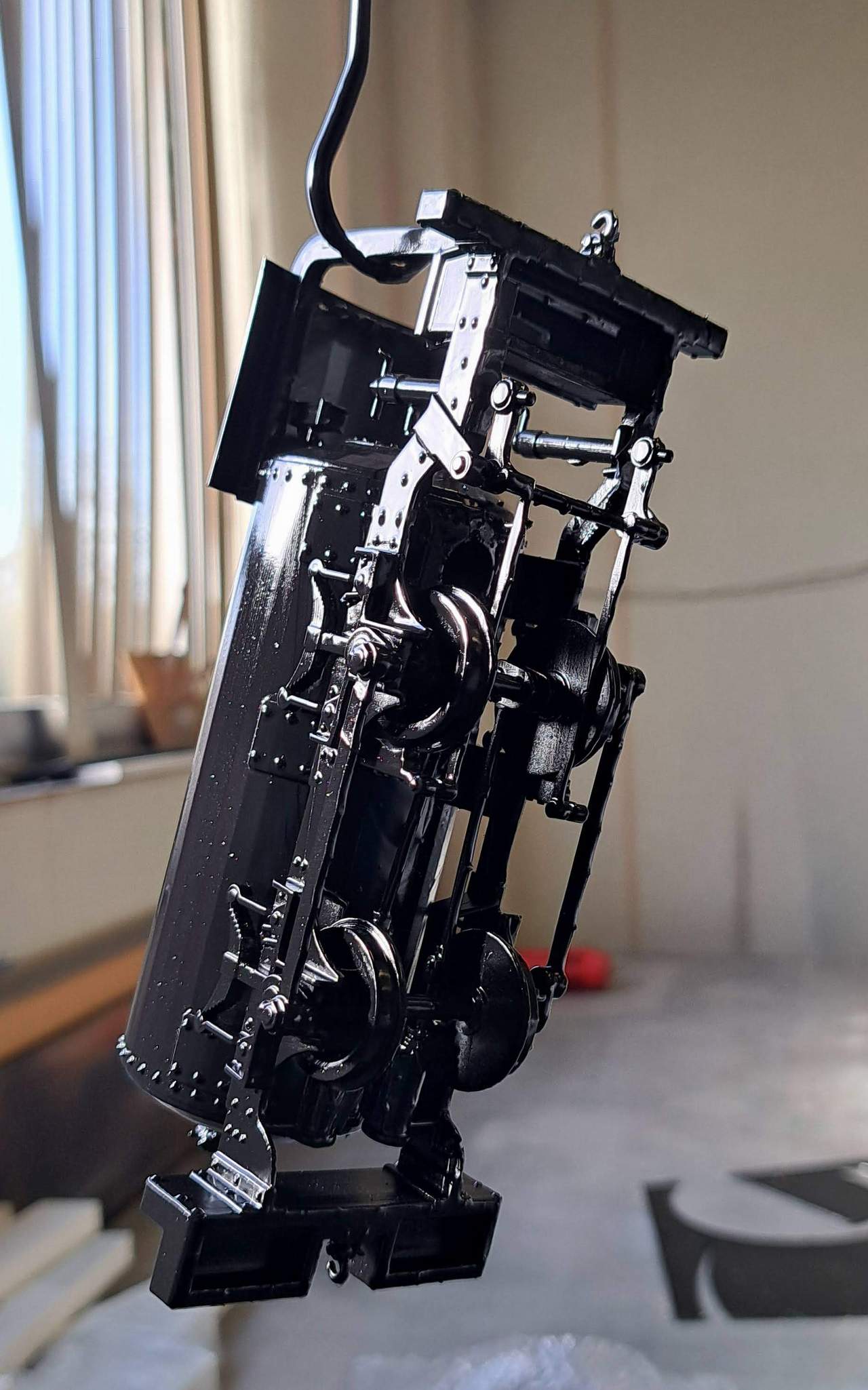
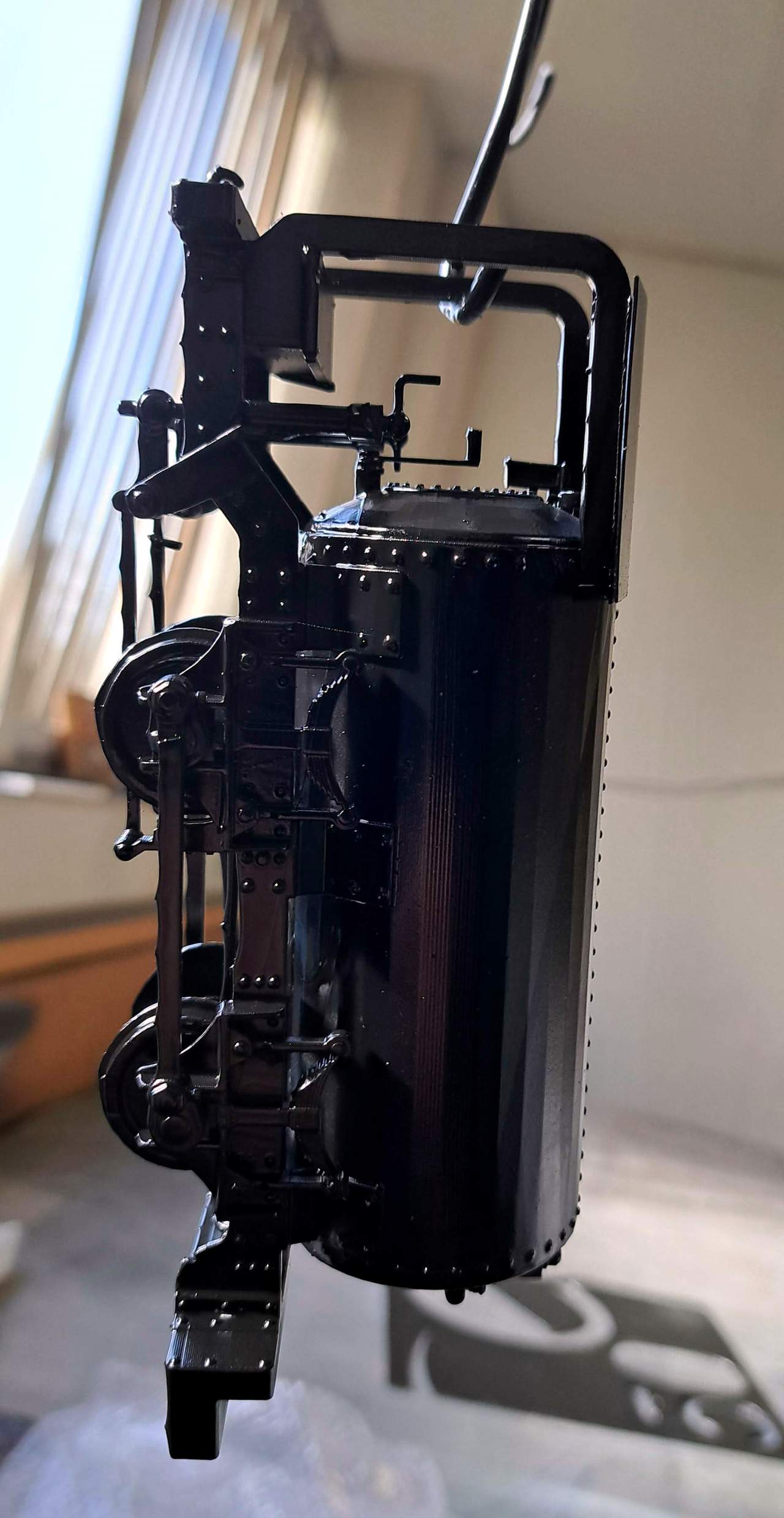
Here is are pics of the current status…

My plan is for this to become a flat car load on a short stub of 2’ track. Not sure if I want to paint it as if it was ready for display at a museum, or rust it completely as if it were just rescued after sitting for what, 100 years?

I’m leaning toward the rusty look, although that will be a lot more work. I would use the Modern Masters Iron Paint and Oxidizer that I still have left from a sign job years ago. In either case, a base coat of flat black everywhere is probably in order.

Too cold and windy to paint here, so I’ll take it to work where I have a ‘paint room’ on Monday.

2 Likes

Jon, you’ve gotten further with this little loco than I have, and it’s great to see!

Below each leaf spring, running down to the chassis, are ~3 little supports you can remove if you feel like it.

Very cool!

Well done on the support removal, Jon. I like your idea of having it setting on a flatcar on a siding. I would lean to the 100 year old rusted piece of history, but that’s just my opinion and I don’t have to weather it :grin:

I agree with Dan, nice and rusty. That would explain why the vandals had removed the reversing gear. :grinning_face_with_smiling_eyes:

The other explanation is that I’d forgotten to include the reversing gear on that print… :neutral_face:

1 Like

Am I assuming correctly that with resin prints, broken off parts can be epoxied back?

Good eye - Thanks. I missed those.

1 Like

I used a Hybrid CA - Loctite HY-4070. It’s an Epoxy/CA hybrid that works on a ton of substrates. I did some tests with various glues, and the HY seemed good. Cliff also suggested the UV cure resin adhesives.

Echoing Jon, CA is really good on the resin prints, as far as I’ve experienced.

Since those printing them already have the same resin in its uncured liquid form, having a UV light and a paint brush allows that to be used as an instant adhesive as well. The drawback though is the need for the light to penetrate. So on a deep crack on an opaque resin part, it depends. If the pieces are already separate, and have a larger contact area, I’d for sure use CA. But on smaller parts, or larger ones printed with clear resin, the UV’d resin can be an option, with the advantage being that the joint probably disappears lightly more.

2 cents…

Here’s a progress update on mine. It accompanied me to work this morning where I have a room dedicated to painting. It’s not a booth, just a room with an exhaust fan. I didn’t have any flat black on-hand so a quick Lowes run produced a can of Krylon Fusion Matte Black. In the photos it looks too glossy, but that won’t really matter.

I agree with those that chimed in that the end result should be completely rusted. I’ll use an Iron paint and an oxidizer to produce real rust. Toward that end, a base coat of black was applied…

I can see that I missed a few more supports sections. I’ll clean that up tomorrow when it comes back home.

Question for @Cliff_Jennings - I’m assuming the end beams and seat are wood. Is this correct? If so, I’ll protect them from the rusting process them paint and weather them as wood.

2 Likes