Getting signals to work in JMRI involves a lot of steps. None of them are particularly difficult, but there’s a lot of fiddly work that you have to do.
First order of business is to draw your track plan. My layout is basically a loop with three passing sidings. Going counter-clockwise, at the top left is Burke. Next, Williamsport is the siding at the bottom left, the branch to Majestic is the switch at the bottom right with no connection. Then we have Dead Rooster Gulch. The yard at Franklin Falls goes off the top. I’ll flesh out both the Franklin Falls and Majestic branch at a later time, since I really want to get the mainline signaled first.
The two digit IDs (FF, 00, 01, etc) are part of the hardware ID for the nodes that will control the signals and track around the switch. This is for my reference and will be removed at a later date.
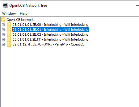
Now we start adding inputs and outputs from the hardware. Here you can see I have 4 of my interlocking nodes plugged in to the system. You can see the IDs are ‘05.01.01.01.2E.xx’ where ‘xx’ is the ID of the node in the track plan. The 05.01.01.01.2E has been assigned to me by the OpenLCB working group as a developer, so I know no other hardware I ever buy from other vendors will have an ID conflict. I need to go into each node’s configuration here and edit the names of the input and output ‘bits’ to an appropriate value. The second screen below shows Block 1, Block 2, etc as inputs, and S1Red, S1Yel, etc, as outputs.
The inputs are for block detection devices, and additionally I can have 4 aux inputs on each node for things like switch detection, etc.
The outputs are for individual aspects on the signal (S1Red is "Signal 1, red aspect) etc. Each bit here maps to a signal light, and then a ‘signal head,’ which I will get to in another post.
Basically this is tedious because for each control point (switch) I need to make sure the 4 sets of signal colors have unique names that I can identify later.