4 Likes
Very cool. I like using those plugs too.
1 Like
Winter work continues on my signaling. Here’s the evolution of a mounting bracket to put the remote signaling nodes into the equipment sheds (which are made out of vinyl post and caps)
Left to right is this is the right size followed by use less filament and then the final allow the bracket to be used as a wire chase

Here’s how the board fits into the equipment box.

And then its pushed up snugly to the top.

Next in CAD right now is the base.
1 Like
I’ve done a complete revamp of the node boards. Instead of having a central master node and a bunch of remote nodes (looking like CMRI hardware to JMRI) I have instead change to have each remote node be its own OpenLCB/LCC node, using the (now somewhat mature) LCC wifi library.
The initial code works like it should, but the hardware on the nodes changed somewhat, so I redesigned the board. Still controls four three-light signal heads, plus has two auxiliary outputs. Four block inputs plus two auxiliary inputs as well. And I added output buffers to increase current sinking capability.


3 Likes
So what !
All that work and certain guests are gonna freaking ignore and blow the signal anyway! While your at it you should also remove the bricks for bumpers on the sidings and use cinder blocks instead.
Finally breadboarded the latest design, and got it working like I think I need. These are about to go out to the fab shop for a test run, and I should have them early next week.

3 Likes
Boards are out for delivery (Not bad, since they were shipped from China on Saturday)
I should be able to have one assembled tonight or tomorrow.
2 Likes
Life getting in the way of actual important things, but the boards did show up. I might get one assembled this weekend. Ah, the anticipation of “Did I get the Eagle files correct?”

1 Like
They damn well better be!

Don’t matter as there will always be that ONE guy that blows the signal target.
1 Like
Summer went speeding by, but I did pick this back up. I have the remote nodes working completely. I need to make one usability tweak for the Eagle files, but the design is solid and the software is 95% complete.

So I gotta ask what are the adjustable pots for?
Those are actually 16-position switches, that change the last two digits of the node address. In OpenLCB, each node needs a unique address, and this lets me change the address on the fly, instead of loading in new software every time.
Looks like the WiFi range covers the RR.

Were gonna start calling you BD Bruce Chubb …You better secure that router cause if it’s open and Radder blows the target he’s gonna blame the neighbors for hacking the signal!
1 Like
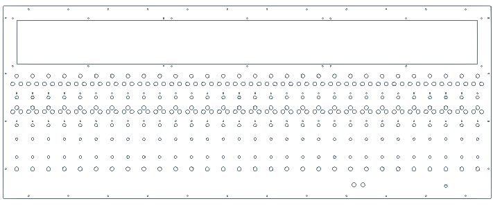
Final design of the OpenLCB/LCC Wifi control point node.

Big board in the center is the ESP32 microprocessor, two ICs on the right the IO chips. The green jumper top middle selects common anode or cathode for the signal outputs.
The dip switches at the top select the node ID.
The banks of holes on the right and left are for spade terminals that connect to the input and outputs (signals, block detection, switches, etc). Power and ground come in top left. The 4 holes at the top center are for an optional OLED display showing the node status.
Total cost per board is <$10.
In other news, I ordered the steel cut for the CTC panel. Took a while to find someone that could cut something 61" long. This should be here at the end of December.
Wow! That’s amazing, I’m really looking forward to seeing it working your signals.
20yrs from now.

1 Like
At the rate I’m going, yep.
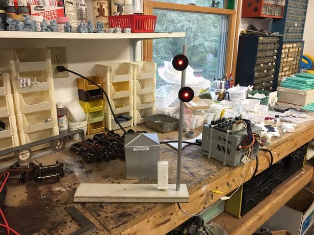
The actual signals are the hard part, at least to make them that they’ll survive outside. I have had a test signal out at the end of Burke yard for several years and it’s survived. This spring I’ll see how the electronics held up.
This guy? If so is it mounted and encased ?
Or is it one of the dwarf signals you made?
This one, actually. Looks like I put it out there in 2018. See this link