Large Scale Central

SD60f Build

Now take some 1/8" styrene and cut two 1" right triangles. Also cut two pieces 1/4 x 1".

Mark the bottoms of the screw brackets as shown by the red arrow, and mount a support on each side as shown.

Note-These brackets are on the outside of the rear of the taper. You can’t really tell in the photos.

Now you can adjust your smoke unit to line up with the exhaust vent on the middle section, and screw it in place.

Now we’ll add some frames to the vents. For the rear vents, I used .015 x .1" styrene. Try not to show a joint at the corners as these frames appear to be one piece.

For the front vents, I used .02 x .06" styrene. For this frame, cut the corners at 45 degrees.

I’ve only shown one side, but make sure you do both.

Now we need to drill holes in the front frames for 3/64" wire. The first wire is 1/8" over the frame, and then the spacing is 1/4".

Now you can cut your wires and insert them into one side of the frame. I used piano wire for the added strength, but it’s a lot harder to work with then brass, so it’s up to you as to which you use.

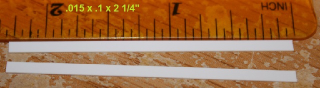
Now we’ll add the vent fins. We’ll use .02 x .25" styrene. Cut twenty three 1" pieces.

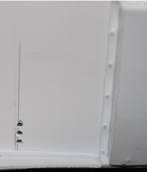
Draw a center line on every piece, and drill 1/32" holes as shown below. Keep the holes in front of your center line.

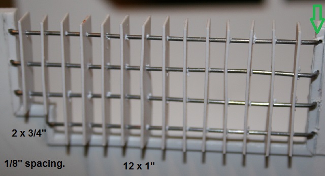
On the conductor’s side, you’ll need two additional 3/4" pieces. They will be short 1 hole as shown below. You still have 1/8" spacing on each end.

The above two pieces are placed first as shown below. Use a 1/8" piece of styrene to set your spacing and keep everything straight.

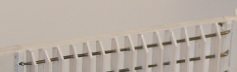
Add the 1" pieces, leaving them bunched up until you bend your wires and insert into the frame.

Once your wires are in place, adjust all of your spacing and then glue the bottoms in place.

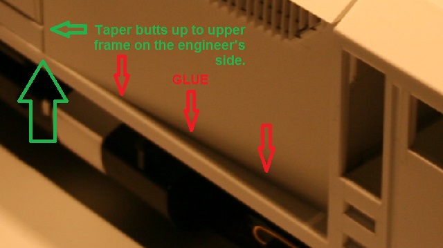
Prototype note- The real units have four additional long fins for a total of sixteen. If you have some 0.1" styrene, you could use that to set your spacing and add the four additional fins. As I didn’t have 0.1", I used 0.125" resulting in the fin reduction.

Now do your engineer side the same way, starting with three shorter pieces as shown below, followed by eleven 1 " pieces. Once happy with the spacing, glue the bottoms into place.

Now take some sharp pointed scissors and trim the top fronts of all your vents. Take off about 1/8" at 45 degrees.

Now cut two pieces of .015 x .1" styrene 2 1/4" long.

Make sure all of your top spacing is good, and then apply the above strips to the top rear of each vent. If they make contact with the frame, that will add extra strength, but if they don’t line up, don’t worry about it. Glue everything good.

Now glue the tapered section to the base. It is the only piece that is permanently attached to the base. On the engineer’s side, it butts up against the end of the upper frame as shown below.

On the conductor’s side, the taper fits over the upper frame. It butts against the spot where the upper frame drops 1/16". Notice how the upper frame does not line up with the taper. It ends 1/4" from the end of the taper.

Now cut a piece of .015 x .1" styrene 5 3/4" long.

On the engineer’s side, glue this piece of trim at the base of the taper as shown below.

Now take some .125 x .25" styrene and cut two 3 1/4" pieces.

These get mounted on each side of the rear of the taper. The center section will slide over these pieces. They will keep everything straight, and help hold the center section properly in place.

They are mounted 1/8" in from the outer edge of the locomotive and sit behind the upper frame.

Now we need to add some detail to the conductor’s side. We’ll need some 1/8" styrene. Cut two pieces 1 x 2". A third piece will be needed for the center. You can use a piece of scrap that is a similar size, like I did, or just cut a third piece the same size.

The front piece needs a 3/4 x 3/8" piece cut out of the bottom right, leaving a small 1/4" tab to the left.

You should now have three pieces as shown below.

Glue these three pieces together.

Now take some .01" styrene and clad the right end and top.

Take some 1/32" brass rod and make two handles about 1/4" tall and with 3/16" spacing.

Mount these 1/8" in from each side of the top. Take some .02 x .06" styrene and run some trim along the top and right side as shown below.

Now take some .04" hex (or rod) and cut ten bolt heads. Apply five to the front and back of the top as shown below.

Take some .01" styrene and cut a piece 1 15/16 x 1 7/16".

Draw lines 1/16" in from the top and right. Mark evenly spaced 8 bolt locations along the top and 6 along the right side. Take a tack, or something with a fairly fine point and gently press into each bolt point. You want to leave a mark, but you do not want to poke a hole.

Flip over, and draw lines 1/16" in from the top and left. (bolt sides)

Now take some .03" styrene and cut a piece 3/16 x 1 3/8". Mount this just inside the line on the left side leaving the 1/16" with the bolt marks hanging out.

Now cut two more lengths of .03" styrene 3/16 x 1 3/4". Cut these lengthwise into triangles.

Mount one 1/16" from the top, one flush with the bottom, and the remaining two evenly spaced in the center.

Cut a piece of .01" styrene 1 13/16 x 1 3/8". Mark and poke bolts on the bottom and left the same way you did above. Mark seven on the bottom and six on the side. Notice the bolt on the bottom right sits about 1/8" from the edge. (Ignore the center line. This is a scrap showing some old marks.)

Flip this piece over and mount it on top of your framework. Flush it to the left side which will leave a bit of a gap at the right.

Now take some .03" styrene and cut a triangle 3/16 x 1 7/8". Mount it on the bottom extended out the left side flush with the bolted frame.

You can see by the red arrows below how it extends out to the edge of the frame.

Okay you should have two fancy pieces as you see below. These mount on both sides of the taper on the conductor’s side.

The front piece mounts on the red x below. It fits over and in front of the frame and should be flush with the front. You can draw a line with a straight edge to help line it up.

The rear piece sits on top (red arrow) of the frame flush with the rear of the taper.

Cut a piece of 1/8" styrene 3/8 x 2 9/16".

Glue this into the bottom of the taper to match the height of the outside frame.

Now measure and cut a piece of .01" styrene to cover the center area as shown below.

Take some .02 x .06" strip and add three pieces of trim as shown below.

Take a piece of .01 x .04" styrene and run one more piece of trim as shown below.

Now from the front edge of the rear vent draw a line down to the bottom of the taper.

Behind this line drill three 1/16" holes with 1/16" spacing.

Cut some 1/16" brass tube and insert in the holes. I placed them over a backwards 1/32" drill bit in my pin vice to insert them.

Keep them protruding just enough to look like a rim around the holes.

I’ll leave you with a teaser photo.

Amazin’

Waiting

(http://www.largescalecentral.com/externals/tinymce/plugins/emoticons/img/smiley-cool.gif)

Rooster

Do you think the factory is as slow?

Sometimes much, much slower…

Like this commercially manufactured product;

The AML GP59/60/60M. How long did it take AML to build it?

Oh yea, they aint finished it yet… So Shane, not only are you doing one heck of a build, you are far and away ahead of the people who supposedly do this stuff for a living.

Ok Rooster?

How about that Sean? (http://largescalecentral.com/externals/tinymce/plugins/emoticons/img/smiley-wink.gif)

What about the SD9? We still haven’t seen an engineering drawing like the GP60… And now the company is out of business.