Sight glasses that never work… I always loved it when the dispatcher (or in your case RTC, I worked from Seattle to Vancouver, BC for a while) would call and ask for a fuel reading. Umm yah, according to the sight glass it looks like we have 1500 gallons still…
You’re right Craig. Many were so old and filthy that they were not readable. Sometimes a good LED flashlight would help, but not always. It’s funny how you tell people about running out of fuel and they can’t believe that happens. I’m sure I ran out of fuel at least a dozen times over the years.
We jumped on a train about 10 years ago that was about 11,000 feet long and over half were empty centerbeams. It was a windy day, and we had to wait for two trains before departing, so I checked the fuel levels. Our head end had 300 gallons and a trailing BC Rail unit was showing 150. Called the RTC and let her know we were out of fuel, and she flipped out and said she wasn’t going to give us priority. I tried to explain that without fuel green lights wouldn’t help, but she didn’t want to listen. I let her know that if we lost a unit on an uphill stretch we’d stall, and she responded “do your best”. We made it about 50 miles which was further then I expected, and lost the second unit. Strangely we got no alarms. I ran back to check it after we lost half our speed and it was shut down and dry. Called the RTC and let her know and she still didn’t care. I let her know we wouldn’t make it over the Lindbrook hill and I got the same “do your best”. Somebody must have clued her in because just before Lindbrook she called and asked if we’d be able to clear into the siding to refuel. Of course I sarcastically responded “we’ll do our best”. We had an SD75I leading, and I thought it might actually get us in, but at about 9000’ it overheated and the load dropped to about 200 amps. A trailing train cut off their power and shoved us to clear and onto a crossing to refuel. The head end unit was showing 50 gallons when the fuel truck hooked up.
Just a normal day at the railroad. (http://www.largescalecentral.com/externals/tinymce/plugins/emoticons/img/smiley-wink.gif)
For the however many times I posted this …once again …Total badass build and documentation Shane !!
Thanks Rooster.
Okay, now we need a pollutant retention tank.
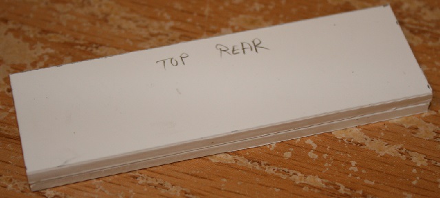
Cut two pieces of 1/8" and one piece of 1/16" 3 1/4 x 1" and glue them together. The edges will be clad so they don’t need to be a perfect match. Mark a side as the top rear and round it slightly with sandpaper.
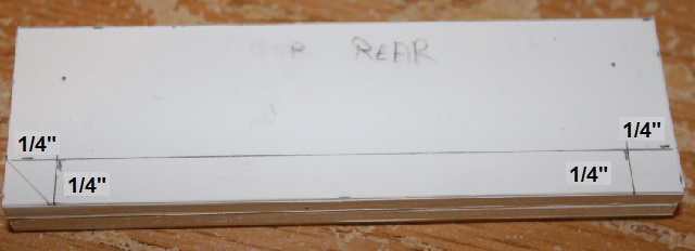
Make a line 1/4" from the bottom, and mark the corners at 1/4" for cuts. make a 45 degree cut on the left side, and cut out the entire square on the right side.

Use some scraps to make some drains/plugs in the square cut. I drilled to take the two pieces of brass bent at 90 degrees.

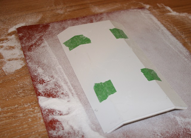
Take some .01" styrene and clad the sides. On the angled side, use one piece to cover the red and green side. On the opposite side only clad the green side.


Now cut a piece to cover the top and rear. Cut 1/4" off of both bottom corners at 45 degrees. Carefully fold it. Cut it a little big so that there is a rim around the edges.

Now we’ll want to center this on the rear of the fuel tank and add some .06" angle on the sides and top as mounting brackets.


Here’s a side shot that shows how the detail looks at the bottom.

One last detail to add before painting the fuel tank. I think it’s the drain for dumping the water, but that’s just a guess.
We’ll need a piece of .125 x .25" styrene cut 2 1/2" long. Drill a hole centered at one end and add a small piece of 1/16" brass rod.

Now we’ll need a piece of 1/8" styrene tube cut 1 1/8" long. Place over the brass rod and glue in place.

Now take a piece of 1/8" styrene cut 5/8 x 7/8" and apply as shown be the red arrow below. The long edge runs left to right.

Flip this over. Now take a piece of 1/8" styrene cut 1/4 x 7/8" and apply as shown be the red arrow below.

Mount this directly above the retention tank. Make it flush with the side of the fuel tank. If your tube hangs down lower then the bottom of the fuel tank, you will have to trim it flush.

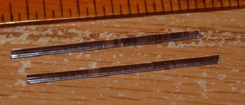
Once your paint is dry, cut two pieces of clear 1/16" rod 1 3/8" long and insert from the top into your sight glass assemblies.
The flash makes it look really blue, but in normal light it looks pretty good. (bottom photo is no flash)

I bought the stuff with a blue tinge, but there was also a yellow tinge available and I’m thinking it may have been a better choice. I think I’m going to make some better looking fuel caps, but that will have to wait for a future update.
You can now add your weight and mount your fuel tank to your base. Next update we’ll start on the tapered section.

“Insane Shane” comes to mind when I watch this thread!
Sean, when I think about building four of these, the same term comes to mind. (http://www.largescalecentral.com/externals/tinymce/plugins/emoticons/img/smiley-tongue-out.gif)I might have to settle for two.
I should have an update posted in the next few days. Here’s a sneak peek at the taper. I’ve discovered that there are minor variations to the tapered section on the conductor’s side. I copied unit 5510 which has a very defined joint at the bend. Unit 5538 in the lower part of the photo has no joint. Another unit has the joint at the edge of the vent frame.

wow!
GREAT build
Shane Stewart said:
Sean, when I think about building four of these, the same term comes to mind. (http://www.largescalecentral.com/externals/tinymce/plugins/emoticons/img/smiley-tongue-out.gif)I might have to settle for two.
You might as well go for the 4 …The first one is always the most challenging. The other 3 will go quickly now that you have everything figured out.
Thanks John.
Rooster, you’re right, but there are a few steps that are a real pain in the butt, like drilling the holes for mounting the trucks.
Today we’re going to start on the taper. This section is not that hard to build. The difficulty will be making the instructions straight forward.
For the base, we’ll need a piece of 1/8" styrene cut 5 3/4 x 3 7/8". This will sit on top of the aluminum angles. Once cut, the front should be flush with the outsides of the aluminum angles. On the front, mark 7/16" in from each side.
Engineer’s side-Mark a line from the 7/16" mark to the back corner and cut off.
Conductor’s side - From the 7/16" mark, draw a line 1 3/16" keeping it 7/16" from the edge. Connect the end of the line to the bottom corner and cut off.


Now for the front of the conductor’s side, Take some 1/16" styrene and cut a piece 1 1/16 x 3 5/8". Cut a second piece 1 1/8 x 3 5/8".

Mount the narrow piece on top flush with the right side. The left stepped side is the front.

Now take some 1/8" styrene and cut two pieces as shown below. Notice that the front and rears are different lengths, so the top cut is angled. The red cut on the shorter piece allows it to fit around the upper frame. The 3 5/8" sides are the fronts.

Now we need to make the vent cuts. On all three pieces, draw a line 2 1/2" from the bottoms. The #1 vents have 1/8" frames, so the cut will be 1/8" over the line. The #2 vents have 1/16" frames, so the cuts will be 1/16" over the line.
Cut the #1 vents first. These are at the rear of both sides, and have 3/16" posts on each side.
Cut the #2 vents second 3/16" in front of the #1 vents. The only difference between the A and B vent is the shape of the front bottom corner. The front posts are 5/8" long.
Note - The posts heights will vary because of the angled top.

Now on the two angled pieces, sand the ends at 5 degrees for a good fit. Mount the short conductor side piece to your base first. It will sit against the aluminum angle. Make sure to keep everything square. Now you can mount the long conductor piece to the base and front piece.

Mount the engineer’s side last. The front will butt against the aluminum angle as shown below.

Once everything is dry, you’ll have to cut a piece out of the rear of the base to ensure that you can get at your fuel tank mount.


Now you can build the roof for your taper. Using 1/8" styrene cut one piece 2 1/2 x 5 3/4" and two 15/16 x 5 3/4" pieces. Build a roof section just like you did in earlier posts.

Now for the front bracing which will support the roof, we’ll need a 1/8" piece of styrene cut 1 1/4 x 3". cut a 1/4" square out of the top corners, and sand the engineer’s side at 5 degrees.

Mount this at the front of the taper. If you set it against the cab, you can use the cab to set the correct height. Line it up with the bottom of the cab roof.

Now we’ll build one for the rear. We’ll need a 1/8" piece of styrene cut 2 1/4 x 3 7/8". Sand both sides of this piece at 5 degrees. Cut a piece out of the top corners 3/8 x 11/16" as shown below.

Set and glue in place. Cut a hole out of the top center to allow the smoke unit to slide in. You can measure or trace the smoke unit. The chimney stays outside of the taper, so do not include it when making your measurements.
The photo shows the cab being used to set the height just as you did for the front.
