
The top one is Shanes … I recognize the green tape! (http://largescalecentral.com/externals/tinymce/plugins/emoticons/img/smiley-wink.gif)
The top one is Shanes … I recognize the green tape! (http://largescalecentral.com/externals/tinymce/plugins/emoticons/img/smiley-wink.gif)
That’s great Sean. Thanks for a good laugh. (http://www.largescalecentral.com/externals/tinymce/plugins/emoticons/img/smiley-smile.gif)
I’m trying to get another update complete. Here’s another teaser photo.
The taper has me stalled at the moment. I’m debating whether or not to permanently attach the roof. I think I’m leaning towards removable, but I need to put some more thought into it.

Hey Shane, this has been great watching and learning how you’re doing everything and documenting it for others to use. These will all come in handy as I’m starting my RS-1 build here soon. I first have to start off with a couple of castings and we’re working on the parts for the molds. Keep up the great work.
Thanks Chuck. I look forward to seeing your project.
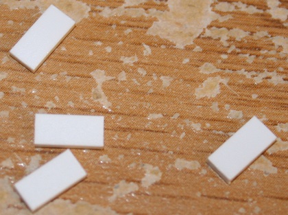
Now we need to patch our fuel tank. Using 1/8" styrene cut two 3/8 x 5/8 and two 1/2 x 1 5/8" pieces. Cut a 1/8 x 9/16" piece out of a corner of the long pieces as shown below.

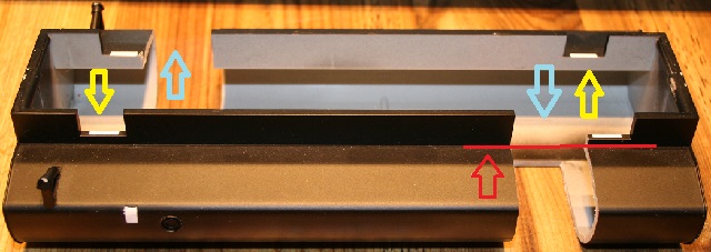
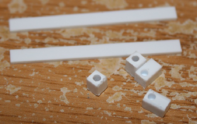
Fill the 2 small holes (yellow arrows) and 2 large holes (blue arrows). When filling the large holes, stay flush with the top of the fuel tank shown by the red arrow and line.
Now take some 1/16" styrene and cut two pieces 1 1/16 x 3". Place them in the two holes in the tank flush with the bottom. Glue them good and let them dry overnight.

Now carefully shape them to match the tank curve and glue in place.

Once dry, cut off the overhang 1/16" below the top of the tank.
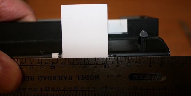
Now for the top of the tank, cut two pieces of 1/16" styrene 1 1/16 x 1 1/4". Make a fairly sharp bend 1/2" from one end as shown below to match the bend in the top of the tank.

Glue these in place. They fit below the frame patch and over the side tank patch. Once dry, sand and fill as needed.

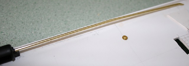
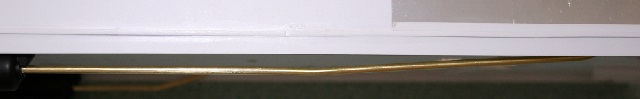
Now take your frame, and on both sides there is a seam between the frame skirt and the upper framework we added. Along these seams, make a bunch of marks 1/32" on each side to help place some trim. Take some .02 x .06" styrene, tape over the seam and glue in place once you are happy with the placement.
Note-this trim does NOT extend to the front of the locomotive. It ends where the upper frame ends.


Now for the corners, take some .04 x .125" styrene and cut four 1/4" pieces.
Apply these to both ends of the skirt on both sides of the frame. (all four corners) The trim will have to be notched at the back corners to accommodate these pieces.

Once they are dry, cut or sand them flush with the step cuts

Now we’re going to attach the air reservoirs and piping. We’ll use 3/32" brass rod for the piping. The ends of your reservoirs should have been drilled in an earlier step.
We’ll start with the engineer’s side (small reservoir holes) We’ll need a 2 1/2" piece of brass for the back pipe. Make a 30 degree bend 1 " from the end of the rod. Drill a hole at 30 degrees in your base 2 " from the end of the reservoir. Insert the rod into the reservoir. You should have about a 1/2" inserted which allows you to adjust when mounted. For the front pipe, we’ll need a 4 1/2" piece. Drill a hole in your base 3 1/2" from the end of the reservoir. Bend the end at 90 degrees. The bend will be roughly 1/2" from the end of the rod. When the piping is put in place, you do not want it poking out of the top of the base.

I installed the reservoir, and then applied glue into the top side of the holes to secure it. You do not need to glue the piping. The fit should be tight enough to hold them in place.

Now on the conductor’s side, we’ll need about 8" for the back pipe. Drill a 45 degree hole 7" from the back of the reservoir. You want the pipe straight for 3 1/2", and then a slight bend to the 45 degree hole.
Now for the front pipe, we’ll need 2". This one comes out of the reservoir, and at 1/2" bends toward the center of the base at 90 degrees. Then 1/2" in it bends at 90 degrees into the base.

Now to mount the fuel tank, we’ll need:
1/8 x 1" aluminum flat-two 7" pieces and two 2 3/4" pieces.
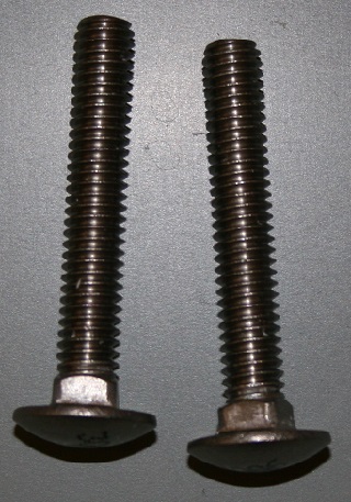
2 - 5/16 x 2" carriage bolts
4 - 5/16"nuts
4 - 5/16" fender washers
4 - 5/16" lock washers
1 - 1/8" styrene piece cut 7 x 1 3/4"
1 - 1/8" styrene piece cut 7 x 2 3/4"
Take your two 7" aluminum flats and the two 7" pieces of styrene. Mark 1 1/2" in from each end. Mark the center of each line.

Drill 5/16" holes.

Make sure that they all match up as these will all be secured together.

Put your carriage bolts into one of the flats and throw on the nuts and tighten them enough to seat them in the flat. You may need to square the holes a little. Once seated, remove the nuts. Place the wide piece of styrene on the bolts, followed by the narrow piece.
Keep everything loose on the bolts and insert into the fuel tank. Now secure with fender washers, lock washers and nuts. Lift it into place. The narrow piece of styrene needs to be a snug fit so that it will hold in place, but with some pressure can still be adjusted between front and rear.

Now place the second aluminum flat on top. It needs to be flush with the side frames. Apply some spacers if necessary.

This is a lifting point, and will also hold weight, so it’s a pretty heavy duty mount. Once the tank is detailed, you can fill it with sand or lead shot before mounting.
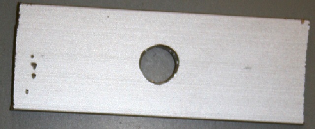
Now earlier we marked the base for the fuel tank. The mounting holes (RED) will be 2 1/2" and 6 1/2" from the front line.

Drill the holes and scar the front and center line with a knife as shown by the red lines. This way you’ll still have them after painting.

On the top side, you’ll need to add a 1/16" spacer to flush the base with the aluminum angles. I used a 1 1/2 x 6" piece. Glue it in place and drill to match the base holes.

Take your two short aluminum flats, and drill holes in the centers.
Now test fit your fuel tank. Place on the flats, fender washers, lock washers and nuts. Before you tighten everything, carefully slide the fuel tank to flush it with the front marker line. Now tighten it up. The fender washers protect the aluminum from the lock washers.

Now before removing your fuel tank, mark the front of the fuel tank, and the center of the fuel cap on both sides of the frame. Now you can remove it, and in the next update we’ll do some detailing.

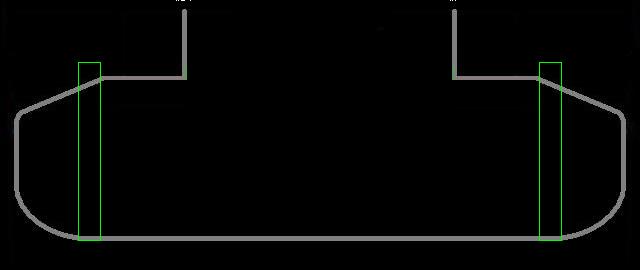
Here’s a cross section showing what we’ve done to secure the fuel tank. The large piece of styrene (red) holds the fuel tank from within. The aluminum keeps everything square. The tops of the fuel frame, and the upper aluminum flat all make good contact with the bottom of the base. The short upper aluminum pieces tie the tank into the aluminum angles so that there is no stress on the styrene. The styrene spacer between the angles ensures that the base plate does not get pulled up between the angles. Clear as mud. (http://www.largescalecentral.com/externals/tinymce/plugins/emoticons/img/smiley-surprised.gif)

Impressive Shane, to the point and excellent progress photos. Thanks from the PAZ!
Thanks Bob.
Tonight we’ll complete the frame detail. We’ll start with the following:
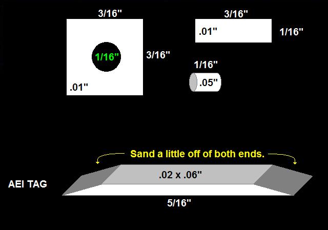
2 - .01 x 3/16 x 3/16" squares. Drill a 1/16" hole in the center.
2 - .01 x 1/16 x 3/16"
2 - 1/16" pieces of .05" styrene rod.
2 - .02 x .06 x 5/16" Sand both ends as shown below.
The first thing we’ll need are the 3/16" squares. These are the emergency fuel cut-off covers.

Center these between the two lines you drew on the frame skirt and mark the hole for drilling the skirt. Keep them at the base of the skirt.

Drill a hole to accomodate the .05" rod. This hole goes through the skirt. The rod is the emergency fuel cut-off button.

Drill a second 1/8" hole half way into the skirt. You can glue the rods into the holes. keep them flush with the outside of the skirt.

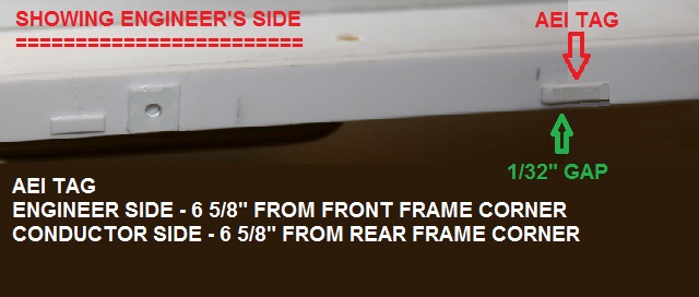
Now you can glue the cover over the botton. Leave a gap at the bottom just enough to be noticeable. Apply the .01" rectangles centered over the fuel cap mark 1/32" above the bottom of the skirt. These are the fuel tags.

Now apply your AEI tags. Notice the engineer’s side is 6 5/8" from the front corner, and the conductor’s side is from the rear corner.
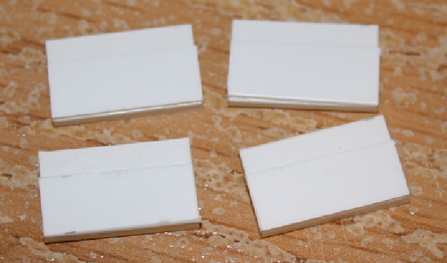
Now we’re going to build the jacking/lift points. We’ll need four 1/16 x 3/8 x 5/8" pieces and four .03 x 1/4 x 5/8" pieces.

Mount the .03" pieces on top of the 1/16" pieces flush with the bottom.
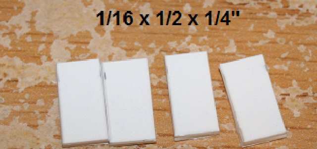
Now cut four 1/16 x 1/2 x 1/4" pieces.
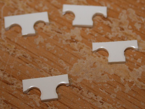
Now punch 3/16" holes against one of the long sides which will be the bottom side. Keep them about 1/32" in from the sides. As you can see below, it doesn’t matter if you break through.

Now cut the bottom corners as shown below. you can sand the front edge of the holes to soften them up a little.
Cut eight 1/16 x 1/8 x 3/16" pieces. Take four and mount them on the back of the above pieces centered and flush with the bottom. The 3/16" is the height, and the 1/8" is the width.

Flip the pieces around, and mount the remaining four pieces as shown below. The long (3/16") side faces front. Let it overhand the front enough to be noticeable.

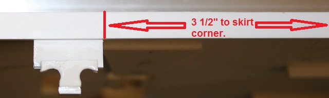
Now 3 1/2" back from all four corners of your skirt, first mount the first 4 pieces you made at the top of this post. The 1/16" piece slides behind the skirt leaving the .03" piece below the skirt. Now take the above four pieces, and mount them on the bottoms keeping them centered as shown below.
Now on the rear engineer’s side, we’ll add some brake detail.
Take some 1/16" styrene and cut one 1/4 x 5/8" piece and one 5/8 x 3/16" piece. Trim the front bottom corner of the 1/4" piece as shown below.

Now mount the smaller piece on the back side flush with the rear and overhanging the top by 1/8".

Mount this against the rear side of the rear jack/lift point. 2" befind it, drill a 3/32" hole and mount a piece of 3/32" brass rod as shown below.

From the front side it should look like the photo below. The brass rod represents a pipe that the brake chain travels through into the rear of the locomotive. The brake wheel is hidden inside the locomotive.

If you want to add any additional detail, do it now. Once complete, paint the base, making sure not to paint the top where the tapered section will be attached.

Now we’re going to detail the fuel tank. We’ll start with the traction motor cables. For the cables, I used some aluminum craft (stringing) wire. It has some type of black coating, is cheap, and easy to work with. I used 14 guage, and 5/64" holes for mounting.
To start we’ll need ten pieces of .04 x .125" styrene cut 1/2" long. Mark for holes 1/16" in from the ends and 1/8" between holes.

On the engineer’s side of the fuel tank, drill 4 holes with 1/8" spacing 1" back from the front of the tank as shown below.

Take four 3" pieces of wire and feed them into three of your cable supports.

Now you’ll have to shape your cables as shown below and feed them into the holes you drilled in the fuel tank. Set all the spacing, and then glue in place. The styrene spacers do not have to sit the same. They just keep the cables neat and tidy. The tail end will be hidden by the air reservoir.

On the conductor’s side we’ll need four 10 1/2" pieces of wire. 3/4" will fold around each end of the fuel tank. Using your remaining seven cable supports/spacers, set it up as shown below. The area with no supports/spacers is hidden behind the air reservoir.

Glue it in place with the ends wrapped around the ends of the fuel tank as shown below.

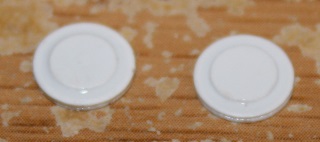
Okay, now we’re going to add a couple access hatches. Hopefully you have a hole punch. Punch two 9/32" circles out of .03" styrene, and two 3/16" circles out of .01" styrene.

Glue the 3/16 on top of the 9/32 centered as shown below.
On the conductor’s side, glue one 1/2" behind the fuel fill pipe.

On the engineer’s side, glue one 1/4" from the rear of the fuel tank.

The detail is really setting this build high. (http://largescalecentral.com/externals/tinymce/plugins/emoticons/img/smiley-cool.gif)
David, these instructions are probably the hardest to share, but it sure brings the model to life. (http://www.largescalecentral.com/externals/tinymce/plugins/emoticons/img/smiley-laughing.gif)
Now we have to add some venting (bleed pipe) details. We’ll need to start with two pieces of .125 x .25 styrene cut 3/8" long. (1/8 x 1/4 x 3/8) Cut these into a triangle as shown below.

Mount these at the front of the fuel tank on both sides. Set them back from the front by 1/16" and flush the tops with the top bend in the fuel tank.

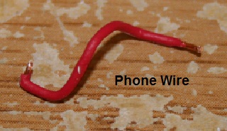
For the pipe we’ll need two pieces of phone wire about 3/4" long. Strip about 1/16" of insulation from the ends.
Drill 1/32" holes as shown below. The two green holes are the same on both sides. The blue hole is on the engineer’s side only, and is 1/8" from the front and centered. The green hole on the side also sits back 1/8" and will be used later on. The hole on the filler pipe is straight into the side of the band you can see in the photo.
To shape your wire, make it drop from the filler pipe into a drip loop and then back up and into the tank.

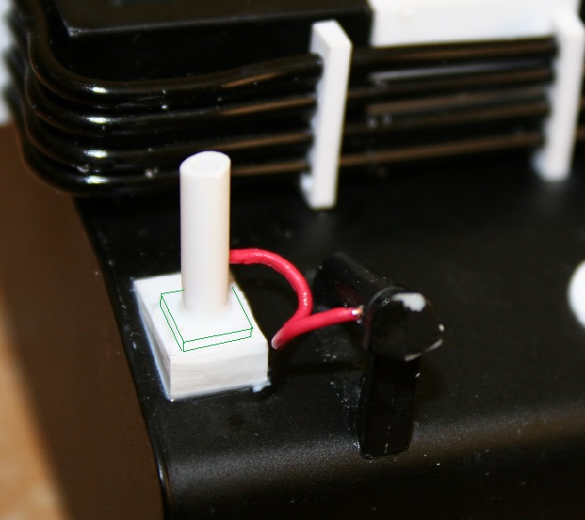
On the conductor’s side, using some .03" styrene, cut a 3/16" square and apply it as shown by the green lines below. Center it between the sides and keep the same spacing at the front. On top of this and centered, add a piece of 1/8" styrene tube about 1/2" long. Make sure that it does not extend above the top of the fuel tank frame. It just needs to be tall enough to disappear behind the frame skirt when the fuel tank is mounted. Drill a 1/32" hole in the bottom, back of this tube for your wire. Apply your wire as shown below.
Now these locomotives use sight glasses for fuel gauges so we need to build a set. We’ll need two pieces of .04 x .125" styrene cut 1 1/2" long, and four pieces of .125 x .125" styrene, two cut 1/8" long and two cut 3/16" long.
The 1/8" pieces are squares. Drill a 1/16" hole through them as shown below.
Drill a 1/16" hole half way through the 3/16" pieces on a long side equally spaced at one end as shown below.
These will be mirrored. Mount the square pieces at the tops with the holes facing top to bottom. Mount the 3/16" pieces at the bottom with the holes facing up and to the rear. (lined up with the top holes.) Take some .015 x .1" styrene, cut two pieces 1 1/2" long and mount them on the insides as shown below. (red arrows)

Now roll them towards each other onto their sides. We’ll need two more pieces of .015 x .1" styrene cut 1 1/4" long. These mount on the fronts (the thick piece is the rear.) as shown by the red arrows. keep them below the tops as shown by the green arrows.

Drill 1/32" holes into the top backs. Only drill through the back piece. Make sure you don’t drill into the 1/8" square at the top.

We’re going to mount these on each side of the front of the fuel tank. Keep them flush to the bottom and the insides line up with the bend in the top of the tank as shown by the green lines below.
Strip some phone wire and run a bleed line as shown below.

