Large Scale Central

SD60f Build

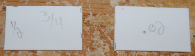
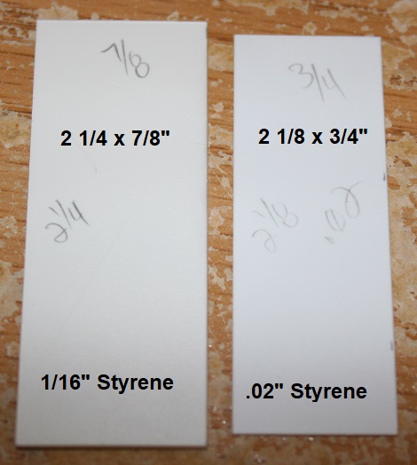
Now we’re going to build the front door. We’ll need a piece of 1/16" styrene cut 2 1/4 x 7/8" and a .02" piece cut 2 1/8 x 3/4".

NOTE - If you are building an older gp38/40/SD40 wide cab, you need to reduce the widths to 3/4" and 5/8". The door is the same, but is 1/8" narrower.

Center the .02" piece on the back of the door.

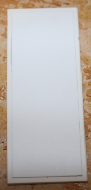
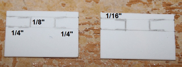
Sand the edges of your door to a slight curve, and then mark it up as shown below for hinges and a door handle.

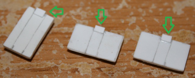
Cut four pieces of .06 x .125" styrene 1/16" long. Glue these on the side of the door as shown below. They do not quite come up to the top of the door. With your door on a flat surface as shown, make sure these pieces extend past the door so that they sit against your flat surface. The .02" piece on the rear of the door lifts it a bit, so make sure these pieces extend right to the flat surface.

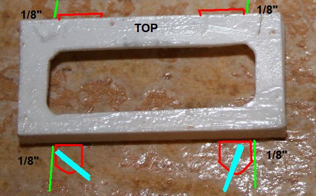
Cut four pieces of .02 x .06" styrene 1/8". These go on top of the door as shown below, flush with the outer edge of the door.

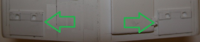
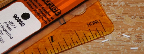
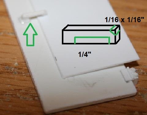
Cut a piece of .02" styrene 1/16 x 1/16" and mount it as shown by the blue arrow. Cut four pieces of .025" rod 1/8" long and mount them as shown by the green arrow. Keep them to the outside of the edge of the door. Now cut some bolt heads from .04" hex and mount them as shown by the red arrows.

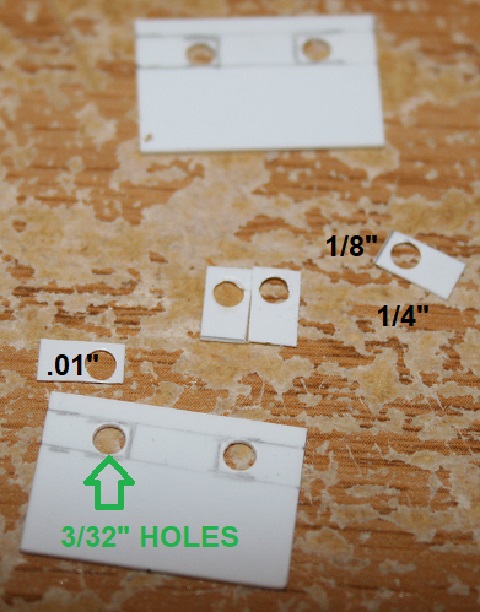
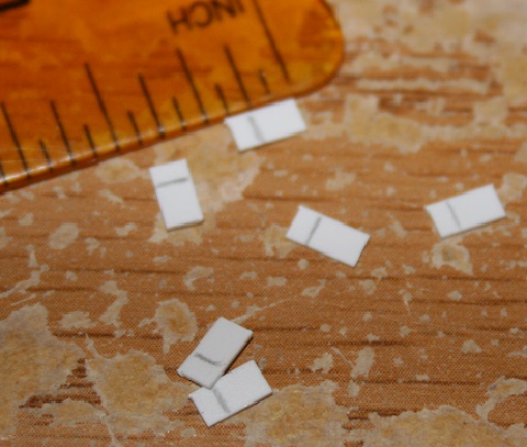
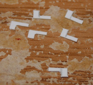
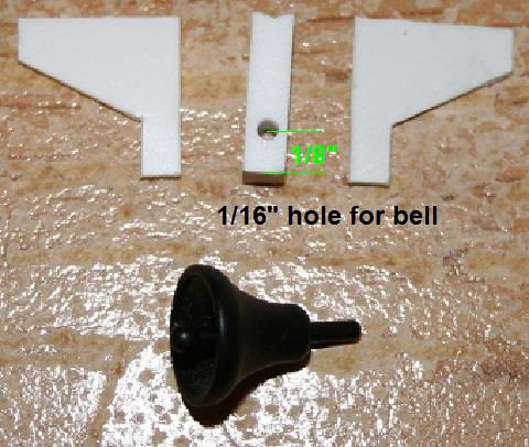
Now for a door handle, I start with a 1/16 x 1/16 x 1/4" piece of styrene. Cut out the green sections as shown below. Sand it to smooth it out and taper it a little, and then mount it on your door. I kept a thin piece of styrene under the inner edge while drying to keep it away from the door.

Now the door will be mounted 1/4" to the right of the center of the nose, and 3/16" up from the base.

NOTE - On the older GP38/40/SD40 units, cut a piece of 1/16" u channel 7/8" long, and mount it centered just above the door as a drip trim. It will extend slightly over the headlight. This trim was not used on the SD60f.

For the bottom hatches, start with two pieces of .02" styrene cut 1/2 x 3/4"

Mark these for latches. The latches measure 1/8 x 1/4". They sit 1/16" from the top of the hatch. The latch will be towards the inside.

Using .01" styrene, cut four pieces 1/8 x 1/4" and punch one end with a 3/32" hole. Punch holes on the inner side of the latch marks on the hatch as shown by the green arrow.

Glue the latches into place, and once dry file the holes to square them.

These mount on the bottom corners of the nose. They are 3/16" in from the outer edges, and 1/16" from the bottom.

NOTE - On the older GP38/40/SD40 units, flip the hatches over so that the latches are at the bottom. There will be a larger gap between the hatch and the door because the door is 1/8" narrower. You’ll have to add hinges to the top as shown in red. You’ll also have to add the bracket shown in blue. You can lock the hatch into this bracket to hold it open.

Now you can add the grab iron detail as shown on page 12 of the thread.

Using 3/64" brass rod, make some grab irons. The measurements are between the curves.

Class Lights WGR | RGW

NOTE-Class lights and number boards are above the windows on the old GP38/40/SD40 units.

We’ll start with two pieces of .02" styrene cut 11/16 x 1/4". Mark center lines for width and height, and mark 1/8" in from each side as shown.

Drill some guide holes.

Gradually work your way up to 5/32".

Punch six 7/32" circles out of .01" styrene, and punch 1/8" holes out of the centers.

Mount the rings nicely spaced as shown below.

Sand the corners of the base to match the curvature of the lights.

Mount these 2" from the bottom of the nose, and 5/16" in from the sides of the nose. This should result in the right hand class lights sitting tight to the door hinge.

Outstanding build log that keeps coming !

I echo the words the chicken said!

That came out really nice Shane , hope to see it running on a video.

mike dorsch said:

hope to see it running on a video.

+1

Hmmm very interesting …

Unfortunately all of my track is piled up in the basement. This spring I’ll have to get something set up in the yard, even if it’s a simple loop to start with. I’ve decided to go with battery power, so hopefully that will speed up layout contruction.

Thank You so much and again great build

Richard

Really top-notch work here!

Wow what a project almost a year in the making. very nice work. Later RJD

outstanding. i also really want to see it pull!

Thanks Guys

Now it’s time for the number boards. Start with some .02" styrene cut 7/16 x 15/16".

Mark the frame 1/8" from the top, 1/16" from the bottom and 3/32" from the sides. The corners will be drilled at 1/8" so mark the 1/16" centers.

Drill guide holes and then work up to 1/8"

Cut out between the drilled holes.

Cut some .03 x .1" styrene for the frame. Cut two pieces 15/16" and two pieces 3/8".

Glue the top and bottom pieces to the back, flush with the edges.

Once the top and bottom are dry, glue the sides into place. You may have to sand them a little to get a good fit.

Cut a couple of base plates 7/8" x 3/8" out of 1/16" styrene. Sand them so that they fit nicely into the rear of the number board frames. If they are too tight, you’ll pop the side frames.

The number boards mount 1 1/2" from the bottom of the nose, 1/16" from the outer edge, and 1 3/16" from the center of the nose. Mount the base pieces centered within these marks, leaving room for the .03" frames. The right hand number board sits snug against the door hinge. Make sure you have enough space for the .03" frame to slide into place.

Now for some detail. Cut eight pieces of .025" rod 1/8" long. Four will be for hinges, and four will be for wing screws.

Cut four pieces of .03 x .1" styrene into squares.

File one side into a nice curve.

Cut four more pieces 1/16" long and mount them on the squared side.

The hinge pieces mount on top 1/8" in from the edges. The above pieces mount on the bottom 1/8" in from the edges with the 1/16" piece down, larger curved piece up with the curve at the bottom. Then mount a piece of rod on top to represent the wing screws. Try to mount them at different angles. (painting note - these wing screws are unpainted brass)

Sand hatches. We’re going to build three sand hatches. Two are for the nose, and one is for the tail.

Front - two pieces of .03" styrene cut 1/2 x 5/16" and two pieces of 1/16" styrene cut 7/16 x 1/4".

Rear - one piece of 1/16" styrene cut 1/2 x 5/16" and one 1/16" piece cut 7/16 x 1/4".

Center and glue the smaller pieces on the larger ones. The lid of the tail end is thicker.

Cut three pieces of .015 x .1" styrene 1/16".

Mark a 1/8" section centered on the short side of the tail lid and centered on the long side of the front lids.

Glue the little pieces you cut overhanging one side by half as shown.

Cut six pieces of .015 x .1" styrene 3/16", and mark a line 1/16" from one end.

Cut about 2/3 out of the 1/8" side.

Mount these on the opposite side of the small tab along the lines you drew.

Cut three pieces of .025" rod 1/8" long.

Mount these as shown below at the base of the two thin pieces to represent hinges. File the top outside corners of the thin pieces to a slight curve. Leave the bottom squared.

The tail end hatch mounts centered and 1/4" in from the end. Facing the tail end, the hinge is towards the right.

For the front hatches, draw a line on the nose from the back edge of the side corner curve up to the bend in the nose hood.

The front hatches mount with the hinge towards the center of the nose. Looking at the hatch from above, line it up with the bend in the nose hood, and the line you drew. From above, it should stay within these two lines.

Run some 3/64" angle along the rear of the nose.

For the rear window frames, start with two pieces of .02" styrene cut 5/16 x 15/16". Mark a 1/16" frame around the edges. Drill 1/8" holes in the inner four corners and then cut out between the holes. Sand the outer corners to match the inner curves.

Center these on the rear windows and secure them. Make sure they do not interfere when the cab is placed against the tapered section.

For the front window frames, cut a .02" piece of styrene 3 1/2 x 7/8". Divide it up into four 7/8" squares. Mark lines 5/8" between the windows at the top. Mark 1/16" frames and mark the inner corners to be drilled at 1/8".

Drill the inner corners.

Cut out between the drill holes.

Separate the window frames.

Cut off the excess at the bottoms. File the outer corners to match up to the inner curves. (not shown)

Tape them into place and once you are happy with the spacing, glue them in.

Once they are dry, you can clean them up as required with a file.

Now on the roof, draw a line 1/8" back from the front edge.

Run some 3/64" angle along this line. End it just before the curve at the outside edges of the roof. Keep the angled corner towards the rear.

Now for the bell mount start with two pieces of .02" styrene 1/2" squares. Mark them up and cut them as shown below.

Cut a 1/2" piece of 1/8 x 1/8" styrene. Drill a 1/16" hole 1/8" from the front, and notch the rear slightly so that it will sit nicely against the bend between the front windows. Insert the bell, and glue on the sides.

Mount it up against the top curve of the cab.

Cut two 1/2" pieces of .01 x .04" styrene.

Glue one on each side of the bell assembly.

Cut four small pieces of .05" round styrene and mount around the top of the bell as shown. I also added a small piece of stripped telephone wire for the air line. I drilled a small hole for the rear and used epoxy to attach the front.