Devon,
OD appreciated your advice as do I! Oh, and we both appreciated the name-number of this loco! Nicely played!
We can’t wait to see this on the rails!
Eric
Devon,
OD appreciated your advice as do I! Oh, and we both appreciated the name-number of this loco! Nicely played!
We can’t wait to see this on the rails!
Eric
Dev,
With all the pains you have taken to detail this loco, you neglected to add the rods to actuate the valves.

Joe Zullo said:
Dev,
With all the pains you have taken to detail this loco, you neglected to add the rods to actuate the valves.
Nope just haven’t gotten that far yet. Next on the list is all the valve gearing. It needs crosshead supports, the rods and the linkage back to the Johnson bar. It still needs a light, the domes and stack, etc. I said it was almost time to move to the tender. There are still a few things on the loco that need to be addressed. One of the most important is all the wiring.
But thanks for looking out for me. Thats why I like to post projects. I appreciate the help, guidance, suggestions. It makes for a better model.
wow Joe, you sure you want to point that out now? he is liable to blow his head gasket on his brain thing!!!
Cute story , years ago when my 36yr old daughter was about 2 we went to an air show, and the local hardware store had a small booth set up and they were giving away foam one size fits most visors to block the sun. My daughter was given one as we walked by and she wore that thing for months, It was labeled 'Air Show head Gasket" and had a image of a Mustang on it wearing one.
Dont worry about it Devon, us diesel people would never know or care if your water heater on rails is missing a part anyway!
Devon Sinsley said:
Joe Zullo said:
Dev,
With all the pains you have taken to detail this loco, you neglected to add the rods to actuate the valves.
Nope just haven’t gotten that far yet. Next on the list is all the valve gearing. It needs crosshead supports, the rods and the linkage back to the Johnson bar. It still needs a light, the domes and stack, etc. I said it was almost time to move to the tender. There are still a few things on the loco that need to be addressed. One of the most important is all the wiring.
But thanks for looking out for me. Thats why I like to post projects. I appreciate the help, guidance, suggestions. It makes for a better model.
Devon,
I SHOULD have known you weren’t finished yet. What was I thinking? (https://largescalecentral.com/externals/tinymce/plugins/emoticons/img/smiley-wink.gif)(https://largescalecentral.com/externals/tinymce/plugins/emoticons/img/smiley-cool.gif)
Joe Zullo said:
Devon,
I SHOULD have known you weren’t finished yet. What was I thinking? (https://largescalecentral.com/externals/tinymce/plugins/emoticons/img/smiley-wink.gif)(https://largescalecentral.com/externals/tinymce/plugins/emoticons/img/smiley-cool.gif)
I am having a bit of a dilemma though. Something I had not planned for was where the end of the crosshead rails are in relation to the driver.
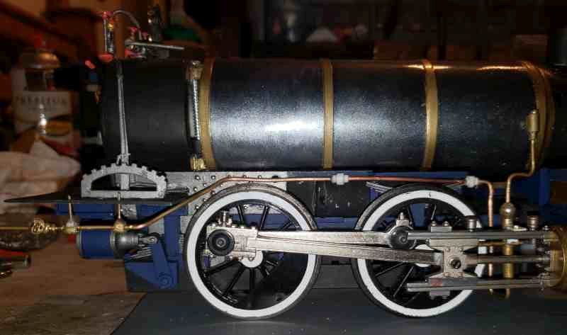
In this pic you can see that it ends well into the side of the driver. i wish i had moved the cylinders back further so that the cross head rails would end up closer to in between the drivers. This would allow me to mount a crosshead support between them. I can mount the bearing and lever between them and extend the rod to the steam chest but not sure how to put in a cross head support. Anyone have any ideas?
Devon Sinsley said:
i wish i had moved the cylinders back further so that the cross head rails would end up closer to in between the drivers.
Are you sure that would allow room for the crosshead to still be outside of the cylinder when fully forward …??? I’m not.
Forrest Scott Wood said:
Devon Sinsley said:
i wish i had moved the cylinders back further so that the cross head rails would end up closer to in between the drivers.
Are you sure that would allow room for the crosshead to still be outside of the cylinder when fully forward …??? I’m not.
No I am not sure. And when I originally placed it thats what I was most concerned with. I wanted to make darn sure I had a full range of motion on the piston rod (or whatever its called). That and it landed where it needed to for the smokebox (although that could have been modified). So I am not really sure I could have move it back any more than it is. I already had to cut almost 3/4 off the connecting rod, the stock one was too long for the current placement. This is a smallish problem. I am sure I will come up with some sort of solution to put a crosshead support on it.
There is already so much going on, especially on the engineers side that I am not sure how much more I can practically cram in there in the way of detail parts. One Idea would be to make the support so that it is between the crosshead rails tying them together and looking like it goes over to the frame to support it. Then I could put the valve rod on that.
Devon Sinsley said:
I already had to cut almost 3/4 off the connecting rod, the stock one was too long for the current placement.
That brings to mind, and at the moment I can’t name and quote a specific source or sources, that there came a point, especially with 2-6-0 & 0-6-0 locomotives, where the railroads and locomotive builders learned that too-short of a main rod made for bad physics which caused several kinds of trouble.
Forrest Scott Wood said:
Devon Sinsley said:
I already had to cut almost 3/4 off the connecting rod, the stock one was too long for the current placement.
That brings to mind, and at the moment I can’t name and quote a specific source or sources, that there came a point, especially with 2-6-0 & 0-6-0 locomotives, where the railroads and locomotive builders learned that too-short of a main rod made for bad physics which caused several kinds of trouble.
Oh gee thanks. I needed that. (http://largescalecentral.com/externals/tinymce/plugins/emoticons/img/smiley-tongue-out.gif)
Devon Sinsley said:
Joe Zullo said:
Devon,
I SHOULD have known you weren’t finished yet. What was I thinking? (https://largescalecentral.com/externals/tinymce/plugins/emoticons/img/smiley-wink.gif)(https://largescalecentral.com/externals/tinymce/plugins/emoticons/img/smiley-cool.gif)
I am having a bit of a dilemma though. Something I had not planned for was where the end of the crosshead rails are in relation to the driver.
In this pic you can see that it ends well into the side of the driver. i wish i had moved the cylinders back further so that the cross head rails would end up closer to in between the drivers. This would allow me to mount a crosshead support between them. I can mount the bearing and lever between them and extend the rod to the steam chest but not sure how to put in a cross head support. Anyone have any ideas?
I have an idea if you are gonna be anal …“connect the Johnson bar first so you can control them” otherwise this conversation is mute?
Right ?
Funky ok?
Extend the lower bar (square tubing) until a cross support from under the frame, behind the wheel can support it. Run a vertical to support the upper bar where it ends.
Rooster,
Me anal? Coming from you that’s kinda funny. I plan to connect the Johnson bar. And that will land on a linkage between the drivers.
John,
I like it. Very doable
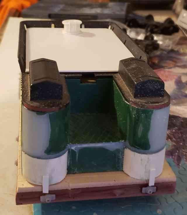
So while I did do some work on the rail truck I am trying to avoid just pushing the loco off to the side. So I did get a start on the tender. It is a New Bright shell on a scratch built flat. The NB shells I think are decent looking except for the way they cut the tank ends. So I added some 1" PVC halves which are nicely the exact same diameter. I trimmed out some of the weird deck also. Added a cover that will serve as a blank to glue on the wood load. It also has the water filler. Added custom built air tank. And the little details are Cliff’s design that Mike Williams printed in resin.
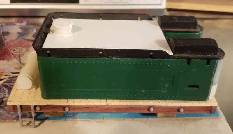
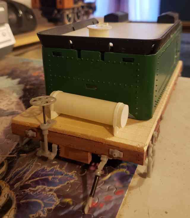
Oh and all the giant holes from the NB ladders will be filled and grab irons added
Gotta love it when a kitbash comes together.
hmmm…
i see, where the water can be filled in.
but where do they fill in the oil?
Korm Kormsen said:
hmmm…
i see, where the water can be filled in.
but where do they fill in the oil?
Maybe it’s a hybrid and there will be a charging port(https://www.largescalecentral.com/externals/tinymce/plugins/emoticons/img/smiley-wink.gif)
Korm Kormsen said:
hmmm…
i see, where the water can be filled in.
but where do they fill in the oil?
I wondered if anyone would ask that. Its not an oil burner. I realize it looks like it with the flat cover but that is just a cover the hole where I will access the electronics. This is a wood burning loco and will have a pile of wood. I will split some twigs and glue them onto the cover so it has a wood load. This is the same thing I did for the 2-6-0

John Caughey said:
Korm Kormsen said:
hmmm…
i see, where the water can be filled in.
but where do they fill in the oil?
Maybe it’s a hybrid and there will be a charging port(https://www.largescalecentral.com/externals/tinymce/plugins/emoticons/img/smiley-wink.gif)
Oh now hey there’s an idea. The first Tesla locomotive