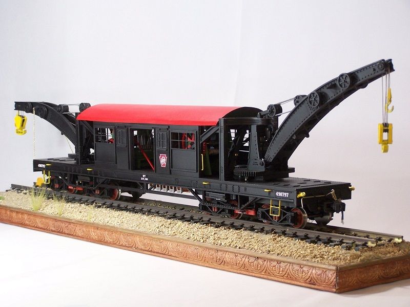
Large Scale Central

PRR 490797 – Double Ended Tunnel Crane

For those that were not at the York D&B, here is my latest 1/29th scale project. This crane was designed to work around, through and under the City of New York. Electric powered, self propelled, it ran off of the 3rd rail or batteries. The model is 100% scratch built from laser cut and etched styrene.

Alan www.thegalline.com

This was a nice model, and this is the Alan I didn’t get a picture of at ECLSTS. Sorry, Alan. Sat across from you at the D&B, but I didn’t have my white board with me.

Nice prototype.

Very cool. Nice job on all that detail. Will it see the track or is it a display?

Beautiful!

Yep, and it looks even better in person. What a fine model!

Todd

Although I designed it to be pulled on a layout, it will probably spend its’ life as a shelf queen. I built it as a capabilities model. I may make it self propelled in the future. I am exploring ways of doing that.

Because it has 4 trucks, the 2 outboard trucks are mounted to the car through a slot so that they can move a good distance side to side. Although I haven’t tested it yet, it should negotiate a 10’ radius. …Maybe.

I will be adding a PRR FM flat to it in MOW yellow as an idler in the next month or so.

I am glad you all enjoy it. It was a lot of fun to build.

Alan

Alan,

Wouldn’t those trucks have been on span bolsters on the prototype?

Bob C.

Bob
I have no idea. all the information I could find on this crane is on this site.

http://members.trainweb.com/bedt/indloco/amtk16000.html

After phone discussions with the site owner, a few other people, and 2 months of research, I found that about all of the information available on this crane was contained on that page. There are quite a few unanswered questions about the car.

As far as the model is concerned, I use a special bolster box (4) I designed, for all of my crane models. The box is designed so I can ballast the car with 3" square iron blanks to lower the center of gravity allowing the booms to swivel and not fall over.

Alan

Beautiful work, as usual!

Thank you Ray.

I have been following your work for years, top notch. The next time you pick up a camera I wonder if you would take a panoramic shot of your layout. With all the new buildings I would like to see how they all fit in.

And by the way, I keep 4 different glues on my workbench. Gorilla brand super glue, for strong parts bonding, cheap dollar store super glue when I need it to flow, Plastruct Weldene for normal styrene gluing and Testors liquid cement for plastic. I use the Testors when I am afraid of melting small or thin pieces. I use the Testors and a large brush when I am laminating styrene pieces or sheets (in front of an exhaust fan). It is the least powerful styrene glue that I have found and it is causes the least amount of distortion.

Alan

Amazing work!

I seen Alan’s crane at the D&B and it is a great piece, I also had never really seen to many railway cranes before and was surprised to run into this piece at Steamtown USA on our way home from York.

The Double Headed Crane became the subject of our Friday night jam session. Very impressive and of course the follow up info on the prototype made it more conversational. Thanks fro bringing to the D&B. Impressive!

Ric

After spending about an hour studying the pictures of PRR490797 I was hooked (so to speak), had to build a model.

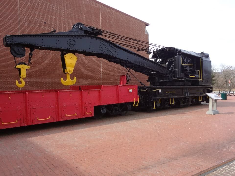
What first fascinated me and had me thinking was, where were the winches mounted. On this crane only the booms turned so that the cable paths became the big topic of discussion in my research. Without some sort of guide system the cables would rub against the framework, in that the booms could swivel 180 degrees (90 degrees from centerline).

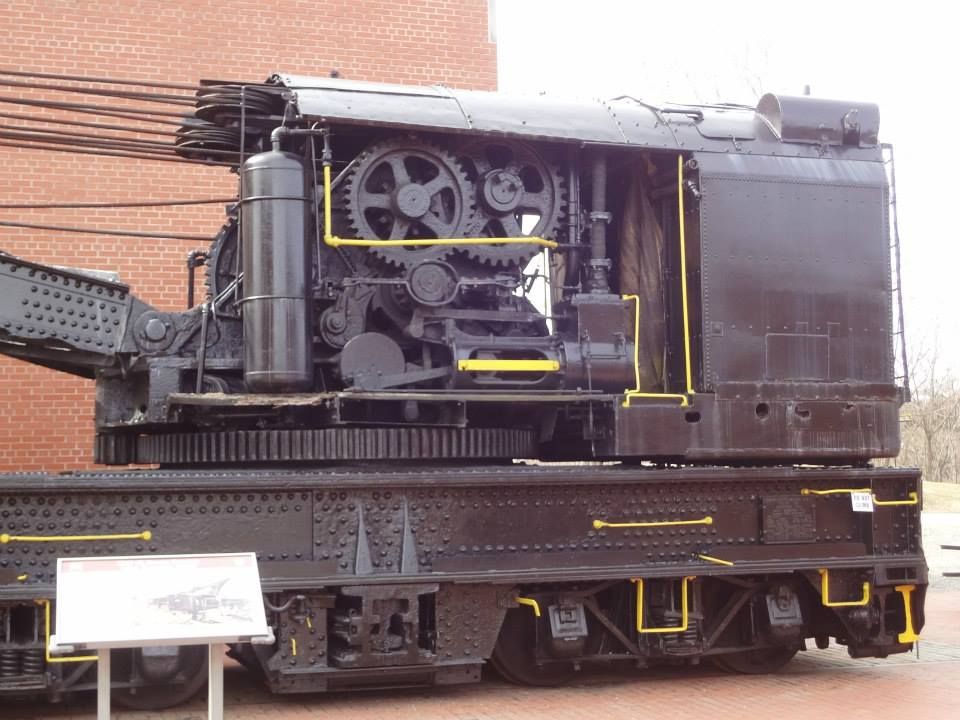
What I deduced from studying the few pictures available, (one standoff profile picture showed the cables coming from the cabin), was that there were a series of sheaves mounted in such a way as to keep the cables on the car centerline. Pictured is my version that contains 3 layers of horizontal sheaves mounted side by side inside the boom mount. When I assembled the design, I found that I could rotate the booms about 88 degrees before the cable hit the frame. Deduction, the sheaves that I used needed to be a bit larger diameter or mounted a little bit further toward the car center.

I am not sure how many drums were on the winches. I went with 3, the basics: Boom lift, large hook and small hook. There may have been more in that I was told that the sheaves mounted outboard on each boom (4 per boom) were actually driven capstans. How they were driven I have no idea and did not find a suitable explanation. The winch side frames also had to be fairly large again referring to the profile picture that showed the cables coming out of the cabin were at different heights, the top cable being over six feet from the car deck. This also required small sheaves within the boom itself to control the cable path up the boom.

Of course the fun part was that the 2 booms could operate independently so that meant 2 of everything.

A little insight into my design.

Alan

Alan Friedland said:

For those that were not at the York D&B, here is my latest 1/29th scale project. This crane was designed to work around, through and under the City of New York. Electric powered, self propelled, it ran off of the 3rd rail or batteries. The model is 100% scratch built from laser cut and etched styrene.

Alan www.thegalline.com

Looks Great!

Neat Prototype

Raising hand to ask two question’s and educate myself as well if I may?

1…Where are the pick up shoes located for the 3 rail?

2…When running on battery power where were the batteries carried ?

Excellent documentation. I know the excitement of finding the answer to a question that you think might not be answerable just because of time. Great work!

Rooster

The electrical pickups are represented by what looks like red horizontal bars at journal level between each pair of trucks in the picture.

Because it was all electric and built back around 1911, along with batteries there had to be a resistor bank. (Used for speed control). I have no idea where these things were mounted. My supposition is that these were mounted on the underside of the car.

Reasoning number 1: I have seen resistor banks mounted that way on other engines.

Number 2 : batteries were often mounted outside of the cabins. Back then and even today they can be quite dangerous. (High amperage and vapors)

Number 3: I am supposing that the interior of the cabin with the 2 sets of winches was built symmetrical like the visible, outside of the car was. When I designed the winch side frames to meet the need for the winches I found that their foot print took up a fair amount of space in the cabin. The original designer’s symmetry is so apparent on the outside that I cannot help but think he carried it over to the interior. With all that in mind, plus the fact that in the cabin would have been a lot of metal like cables and stuff, plus enough batteries to move that car at 35+ mph, plus the high voltage and amperage of the resistor bank I have to think they were mounted underneath for safety.

If you look at the picture you will see that I mounted a resistor bank under the frame in the center. I have it mounted on a box that represents the batteries.

A lot of educated guesses.

Alan

It was great seeing it in person. Amazing model and the details are amazing.

Alan Friedland said:

Todd

Although I designed it to be pulled on a layout, it will probably spend its’ life as a shelf queen. I built it as a capabilities model. I may make it self propelled in the future. I am exploring ways of doing that.

. . . .
I am glad you all enjoy it. It was a lot of fun to build.

Alan

Awesome model, and interesting details - thanks for the insight.

As far as making it move - there is a recent thread about the NWSL "magic carpet’ drives, now obsolete, which were just a motor attached parallel to the axle and driving through a big spur gear.

Peter Spoerer in the UK makes a similar drive http://www.peterspoerermodelengineers.com/90275/info.php?p=7