Large Scale Central

New RC Train Control

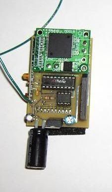
Thought I would create a thread on an RC system I started developing this year. It is based on radio systems I have incorporated into other projects. I appreciate any feedback on the system. I will attempt to explain the overall direction and trade-offs made in design so far. The radio control system consists of a transmitter and multiple receivers. There are both locomotive and accessory receivers. The system is currently limited to controlling 32 simultaneous locomotives. 100 non-locomotive accessories can currently be addressed. One of the main requirements of the system is low cost. At this time the transmitter costs under $120 in parts and each receiver with motor controller is under $70. Remember this is single unit development costs and the devices must be soldered together and programmed. The transmitter controls both locomotives and accessories. It is microcontroller based and operates over inexpensive 433 MHz data radios. The transmitter has an LCD display, 12 key matrix keypad, two push button switches and a rotary encoder for speed. Here is a picture of the transmitter:

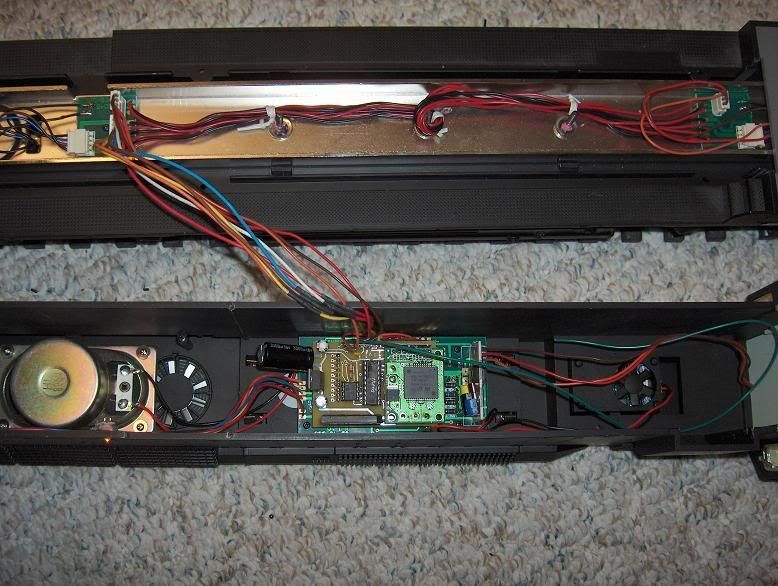
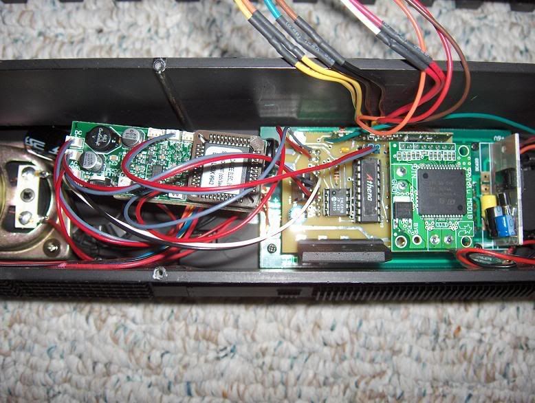
The receivers are designed around the Aristocraft DCC plug and provide control over locomotive functions. The following is a list of capabilities: - Speed control (256 steps) - Direction - Directional lighting - Bell (latched) - Horn/Whistle (momentary) - Accessory 1 (latched) - Accessory 2 - 4 (momentary) - 30 amp DC motor controller (14 amp without heat sink) - Overvoltage protection - Thermal protection - Fail safe shutdown on signal loss (from transmitter) - Setup storage of address, motor control, and default direction - Open digital radio design (433 MHz, 315 MHz, other) - 100 + yard range - Short antenna length - Minimized radio interference from other sources - Reliable operation on even dirty track - Ability to operate on battery - Ability to operate on AC track voltage Here is a picture of the receiver with daughter card motor controller:

Here is a picture of the receiver plugged into an Aristocraft SD-45:

Operation is very straightforward. Here is a video showing operation of three locomotives simultaneously: [url=http://s68.photobucket.com/albums/i27/rmcintir/Robotics/?action=view¤t=HPIM2909.flv]

[/url] Currently the system uses 433 MHz data radios operating at 2400 baud. I have tested several different manufacturer’s radios with good interoperability results. Other frequency radios could be used with similar results. The system is designed around a single transmitter. I am currently working on handling multiple cabs via an interface to the main transmitter. The first interface will be to a personal computer which will provide both multiple cabs and automation. Interference is always a concern with radio control systems. The system is fairly immune to outside radio interference. The only interference recorded so far has been from another 433 MHz transmitter operating continuously next to (or between the transmitter and) locomotives. If the intentional interference was located outside the line of site of the receiving locomotives there was no noticeable interruption to operation. Two way transceivers were not selected in order to control costs of both the radio itself and the additional complexity and expense of higher capability microcontrollers in the receivers. My original design concept called for Zigbee transceivers but the development radios are quite costly and unless purchased in significant quantity receivers are simply too expensive. Hopefully this will eventually change and the radio protocol will not exclude using these radios in future designs. A single transmitter was selected to reduce complexity. All traffic to locomotives and accessories must flow through the main transmitter. This is to allow a single device to maintain the status of all controlled devices as well as simplify the radio protocol. Typically a single engineer will be controlling multiple locomotives so this design constraint provides for faster development. As noted above multiple cab control is being designed and will initially be through a PC interface, possibly with wireless devices. While this adds to the complexity of supporting multiple cabs it allows significant capability for automation and a wide variety of wireless ethernet devices to be incorporated as cab controls. Once I have the basics worked out I plan on publishing everything required to build the transmitters and receivers and open the basic wireless protocols and microcontroller programming. If you have any ideas or concerns please feel free to let me know. Now is the time as it is still fairly early in development.

Russ
looks great. I could not get the video to play.
Also I think you said in a Diff. post that you are using track power? if so glade to know that as all I run is track power.
Would love to see a computer interface. I run my Christmas lights with my computer it would be cool if I could set up the trains to work off the computer as well.
Look forward to finding out more and see more.
Thanks and welcome to LSC

Geoff George said:
Russ looks great. I could not get the video to play. Also I think you said in a Diff. post that you are using track power? if so glade to know that as all I run is track power. Would love to see a computer interface. I run my Christmas lights with my computer it would be cool if I could set up the trains to work off the computer as well. Look forward to finding out more and see more. Thanks and welcome to LSC
It's a flash movie I think, try this URL to see if it works:

http://s68.photobucket.com/albums/i27/rmcintir/Robotics/?action=view&current=HPIM2909.flv

The receivers will run with either track or battery power. I have done both. I set up my SD-45 with two battery packs (about 15 volts) and it worked great. It also can work with AC power (not PWC) to control DC motors as the bridge rectifier is rated at about 20 amps. I don’t necessarily recommend it but it will work. I’m thinking of adding a place for a switch on the receiver to select between battery-RC, RC-track control, and track (DC voltage) control. It’s something that can be added by anyone after the fact but putting it on the receiver pc board might make it easier.

I had all this information in another post but I removed it as it really didn’t belong there, my mistake and apologies!

I’m working on the PC interface. Technically the 100 accessories could be used to control your Christmas decorations as well. I haven’t done as much development work on those. I’m torn on whether to have one accessory receiver react to multiple accessory addresses, i.e one receiver can be designated as addresses 0-15? Right now the non-locomotive receivers are just simple on/off device definitions but they could potentially be set to 0-255. Your thoughts would be valuable on defining those better. I already like the Christmas decoration connection! :slight_smile:

I want to point out that this system is intended as something for people to make themselves. My intention is to provide the ground work for an open RC system for trains that can be expanded. Heck, I would love to find someone else post code for me to control a locomotive via a wireless Nokia 770 web browser interface eventually (ok, maybe I’ll write that one). While I have only been working on this since Jan 6 of this year I have been thinking about it for many years, that’s why I have made the progress you see so far. I’m not sure when it will be ready for the general public to build. I’m actively working on a magazine write up at which point it will be available. Another electronics article I wrote which is not train related should come out next month. I’ll know more about timing after that happens.

Russ thank you for your note.

My outgoing E mail service will not let me reply to you when an E mail is sent from here.

I checked my profile and it did not allow emailing from forms. It’s fixed now. Missed that in the setup!

So if it works on track power as well, could it be another substitute for the Aristo TE?
Not the on-board TE, but the unit that goes between the power supply and the track.

I selected the motor controller for its small size so it would fit into a locomotive. Technically it should work to power the track instead. I might pick something more high power. The motor controller does have short circuit protection as well. Of course the receiver could always be used to provide a PWM signal to some other existing device to vary the voltage. Perhaps even plug into the hand held for an MRC Control Master 20. I haven’t looked at how the hand held works.

Russ is it hard to put the items in the loco that are needed to make them work ?
I’m not real good with that kind of stuff. OR is it going to more of a plug and work kind of item?

Geoff George said:
Russ is it hard to put the items in the loco that are needed to make them work ? I'm not real good with that kind of stuff. OR is it going to more of a plug and work kind of item?
Geoff - I think this is intended to be a DIY project for the electronics tinkerer. If you are not comfortable figuring out the wiring in a loco, you probably wouldn't be wanting to build one of these from a pile of parts (or just a parts list). Russ has used the Aristo plug as part of his design spec, but you need to build the receiver board yourself first.

To me, this looks like something fun I could solder up at the picnic table while camping :smiley:

Jon Radder said:
Geoff George said:
Russ is it hard to put the items in the loco that are needed to make them work ? I'm not real good with that kind of stuff. OR is it going to more of a plug and work kind of item?
Geoff - I think this is intended to be a DIY project for the electronics tinkerer. If you are not comfortable figuring out the wiring in a loco, you probably wouldn't be wanting to build one of these from a pile of parts (or just a parts list). Russ has used the Aristo plug as part of his design spec, but you need to build the receiver board yourself first.

To me, this looks like something fun I could solder up at the picnic table while camping :smiley:


in that case Jon do two. :smiley:

I’ve designed it up and am going to try to get it published in either Nuts & Volts or Servo magazine. It will have all the info to make it yourself, even the pc board design. The magazine likes it when a kit is also offered so I may offer the boards in some state of completion. The receiver boards are pretty easy to solder. The motor controller is from a supplier, it uses surface mount components that are already soldered. Only the pins to plug it into the receiver board are needed to be soldered and that is quite easy.

The transmitter’s CPU board is already available from a manufacturer. It is very easy to assemble yourself but also offered complete I believe. I originally planned on making my own transmitter board layout but the one they had worked so well there was no real advantage. The enclosure is just a radio shack box with the holes cut out for display, keyboard and switches. I’ll have info on how to do that in the article as well. The enclosure is WAY bigger than it needs to be but it fit comfortably in my hand so I like it. Your mileage may vary, I do see real advantages in the small remotes that RCS has!

As to installation into a locomotive. If you have an Aristo engine with the DCC plug the receiver should plug right in when complete. I’m still waiting on my new sound board from Dallee, when I get it I will work out the best way to connect it (and other RC type sound systems). If you don’t have a DCC plug you can connect it much like a typical DCC decoder to the locomotive wiring.

Jon, that’s my kind of campout! :slight_smile:

Looks like a very interesting project Russ. I look forward to seeing more detail. I have messed around with some 433 MHZ stuff myself and didn’t have much luck. 30 amp motor controller? Who’s board are you using? A bit of overkill don’t you think?

I’m an avid Nut’s n Volts reader. Good luck on your article!

I was told N&V was going to publish an article I wrote a while back in the March issue. I hope it makes it. It isn’t train related but I will have an idea of how to link to the final article when it’s all done so I can share it. I think this one will be a series of articles, it’s a bit involved for just one issue but I haven’t heard back on that yet. I’m probably going to send them my first article installment when I get over the flu!

I do a lot of error checking with the 433 MHz stuff, the radios are also picky about alternating 1s and 0s as much as possible (balance) when you transmit. The best method for receiving the data is to use a hardware UART rather than rely on software in the microcontroller. That way you don’t miss any data sent and timing in the receiver loop isn’t as critical. I tried a software receive buffer but it was just too unreliable. The Hardware UART will receive by the second transmission every time.

The 30 amp motor controller is overkill but that current is with a heat sink, without it’s about 14 amps. I wanted to make sure my SD-45 which is supposed to have a stall current of 9 amps wouldn’t over power it. It’s the biggest thing I have. That controller also seemed the best buy for the buck and is a perfect size. It’s from Pololu, the VNH2SP30 motor carrier. It provides current feedback but I haven’t needed to use it yet. No back EMF, when I tried it there was too much noise as I had to stop the PWM to read the motor speed then turn it back on. I didn’t seem to get any significant advantage, even on the rougher running engines, so I didn’t pursue it. Also, it would have required a significantly more expensive microcontroller in the receiver.

Pololu’s cheaper motor controller has some serious problems with self destructing when it is fed too high a voltage or too high a PWM frequency. Ask me how I know… Fortunately I didn’t destroy the VNH3SP30 but it must now be run at a pretty low PWM and I really need to watch the track input voltage. It’s definitely not the same as when I first got it. It’s a little noisy compared to the other locomotives now but it’s a great test receiver still (it’s in the little 2-4-2 Bachmann). I don’t recommend that one for my application but it has other very good uses. Remember the motor controller is the most expensive part of the receiver, everything else is pretty inexpensive. The receiver is designed to handle any standard H-Bridge wiring but the daughter card plug-in is designed for the Pololu unit.

I finally received my Dallee sound board for the SD-45. Sound isn’t too bad, especially for $76. My receiver controls bell and horn fine. I didn’t have access to a sound board and had assumed that the bell needed to be latched, turns out it turns itself on and off with a momentary press of the button so I changed the bell signal to momentary. If other sound boards require something different let me know and I can incorporate a change per locomotive. Here is a video of it running: [url=http://s68.photobucket.com/albums/i27/rmcintir/Robotics/?action=view¤t=HPIM2910.flv]

(http://i68.photobucket.com/albums/i27/rmcintir/Robotics/th_HPIM2910.jpg)

[/url] Here is a picture of it installed into the SD-45:

(http://i68.photobucket.com/albums/i27/rmcintir/Robotics/Dallee_sound_and_receiver.jpg)

I use the power, speaker and motor connection on the Aristo DCC plug and the bell and horn plug on the receiver board. Very simple installation, total 8 wires. I also put a cap across the DC power plug on the Dallee sound board to insure it operates without a hiccup though small power interruptions.

Probably the best thing to do is to make all outputs capable of latched or momentary.

Bells are normally a toggle, hit it, and it changes state.

Some horns are a momentary trigger, some are on in a latched state. Some sound cards have both.

I assume your “outputs” are open collector to ground?

Regards, Greg

Yes, outputs are open collector to ground for lights, bell and horn. The other accessories are through a separate relay board and can be setup to go high or low. I may try to squeeze them onto the main receiver and use a quad optoisolator. I’m recoding to make the controls either momentary or latched. Thanks for the input!

If you want the other accessories and all you need is TTL signaling and won’t sink more than 20 mA then the lines can be used directly. Turns out the Dallee sound board I have supports the on/off function for sound so I connected one of the TTL level accessories to control this and it works great.

Thought I would put up a link to a quick video of installing my receiver into an SD-45. It shows a Dallee sound board piggybacked to the unit. I’m going to make another video or two with my real video camera.

http://www.youtube.com/watch?v=jSJ_jEwZd8s

keep us posted on this and when/where to buy the magazine with the article. I had never heard of thos mags, but I’m not an electronics guys by any means.

I thought I would update and let anyone interested know that I have added Back EMF to the receiver logic. It works amazingly well in initial tests. Right now the operator sets the desired speed for the locomotive. If that speed does not cause the locomotive to move the receiver speed will be bumped up until minimal movement is achieved. If the locomotive is loaded down on a hill for instance, and the wheels stop it will add power and keep moving.

Right now I only use Back EMF to insure the locomotive moves. I don’t have it set up to maintain a particular speed. In all honesty I didn’t have it in mind when I started the project and didn’t design the electronics to provide that kind of feedback. It does work well to insure low speed operation under varying loads which is what I wanted.

It will be a while until I send the new receiver design out. I’m also incorporating speed tables and MU capability. Also going to upgrade how accessories are controlled to allow more flexibility. The microcontroller upgrade in the receiver has exponentially increased the capabilities of the system and it only increased the parts cost by about $6.00 Not a bad trade.

I haven’t heard back yet on whether the magazine is interested in publishing a how-to series. Either way it will be about a month before I complete the new receivers and upgrade the transmitter software. I did make a PC interface to allow multiple cab control and automation.