Large Scale Central

Major K27 overhaul

OH NO!!! Now I am gonna have to start all over again…NOT!

Yeah Greg, I knew they were the wrong way, but I figure that heat sink is so far overkill I don’t think it will make much difference.That sink came off of a 2gig Athalon processor. Way more heat than I am likely to build up in my application.

just having some fun, looks more than adequate. Too bad you could not find a small switcher to do the job, but sounds like you need 2 voltages.

Regards, Greg

Greg,

The first Regulator came as a result of a couple of emails with Phoenix Sound, reviewing a preliminary version of the wiring diagram I posted. The second is the result of not having a small fan that will tolerate 18vdc. All the small fans I have are CPU fans that are either 5 or 12 volt. Go back and review the wiring diagram as I have replaced the original with the latest version.

Bob C.

Yeah… I keep my eyes out for 24v fans, perfect running on 18v…

On other ones, I have put two 12v fans in series on 18v and works well too… seems I have amassed a pile of 12v fans (I get a lot of old laptops I strip for parts).

Regards, Greg

What a coincidence. I’ve had a couple of lap dancers I stripped too!

laptop Andrew not lapdance :slight_smile:

Yeah Andrew I can believe that, but then again Saloons went out of vogue how long ago??? :slight_smile:

Well, another update, and it doesn’t look like much. Spent 4 hours this evening working on finalizing the connections at the D-Sub connector and routing wiring to the general area of the final destination. Still to do is find a small fuse holder that will hopefully mount through the floor and not interfere with the trucks, mount the diode provided by CVPUSA, and install the fan in the floor.

Here are a couple of pics of today’s work.

Wiring A

Wiring B

I finally figured out you are using a standard VGA connector for your external connections.

Quite the project!

Greg

Greg,

Yeah, I was quite surprised when I looked up the connector and it was rated at 3A per pin. That was what made me decide to utilize that connector for the project. Most of the wire runs are control circuits not requiring high (for our application) amp loads. And looking at the wire gauge running between the loco and the tender, combined with my fried traces on the board in the loco and wire gauges connected to that board I figured the VGA connector would be a good fit for my application. Time will tell whether my assumptions are good or not.

Bob C.

Zip ties what an invention!
Looks very neat and profesional even! :slight_smile:
Hope the outcome is as pleasing.
Keep up the great work.
Hope to see a video when all is done!
Sean

Sean, Thanks for the compliments, they are appreciated. It is my intent to do a video at some point. It will depend on how well my old trusty Cannon Power Shot A560 will perform on that given day. Some days are better than others.

Tonight’s update is brought to you by ‘Dremel Lotsa Dust’. I cut the holes in the floor for the fan and mounted the fan. Doesn’t sound like much but when it is all fit as you go it takes extra time.

Here is the way I cut the floor

Floor Opening

And here with the fan mounted. I reused the mounting screws from the side weights in the tender. It got too late to cut them, so that will be tomorrows starting point.

Fan Mounted

Closing in on the end :).

Bob, which way is the air flow?

Greg

Greg, I have chosen to have the air flow is from outside to inside. My belief is that the fan turbulence will assist in getting air into places that laminar air flow will not. I will be adding exit holes in the front of the tender as well.

Another bit of update from this evenings work. Mostly just making connections and tying up loose ends. I still need to locate a GMA size fuse holder for the common power supply upstream of the diode provided by Phoenix. Any way here’s todays.

Cleanup A

Cleanup B

The remaining leads that are not connected are: WHT/ORN and BRN/BLK are the remaining power connections and the PNK and GRN are the chuff sensors. I still need to figure out the detail of how I am going to arrange that - directly on the Bachmann board or make a small sub-board.

Getting down to the short strokes. The weather prediction for the weekend is pretty rainy, so I may be able to get this finished. Crossing my fingers any way.

Due to possible track debris I would force the air down when a fan is near track level.

Just a thought esp for outdoor running.

It is a good idea to make a hole for the air to flow whichever way you blow ; not being overly familiar with the thing you’re working on , I don’t know if there are sufficient gaps in the structure already . If there is not enough flow , the fan can overspeed and won’t be helping the cooling anyway . The total hole area should equal the area of the fan mounting hole . In practise , the “new” hole should be as far away as possible from the fan .

Mike , sitting back on his locos and waiting to be shot down .

Dan - I have a rather fine brass screen I will be installing over the opening on the exterior for that purpose. Plus I don’t believe a CPU fan will move enough air to pick up debris off the track. I am going to have to deal with general dust regardless. May have to open up and clean a bit more often.

Mike - I made comment above that there were additional hole to be drilled in the front of the tender floor for air flow exit. I spent 15 years doing air handling and am very aware that, per se, I am not following ‘best practices’, but then Bachmann never intended the amount of electronics I am mashing in that space. Extreme circumstances require extreme measures.

Bob , I had noticed your reference to air holes ; other people may not get the point of them . I spent half of my life keeping things cool too , and the lack of knowledge about it----as you will know----can be a bit of a disaster if insufficient care is taken . (I worked on Radar development among other things)

Mike

Mike Morgan said: Bob , I had noticed your reference to air holes ;

Is that the same as a water letter outer ? r?

[youtube]http://www.youtube.com/watch?v=NxEOiqtV_MA[/youtube]

Bob, I think I would do it the same way as you are doing it.

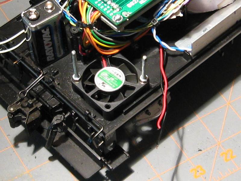
First, I have learned a bit about cooling “consumer devices” in my career, and one precept that seems to be pretty much universally accepted is that unless you are force cooling with a huge fan and ducts, don’t fight the direction of convection currents.

Those will be upwards in conditions you would encounter (outside, and sun shining on a black object).

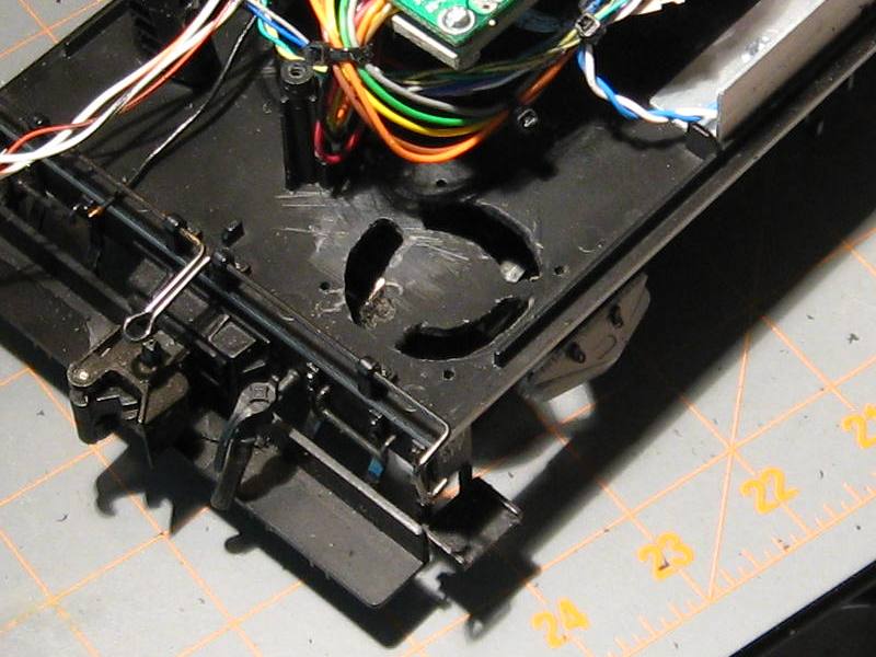
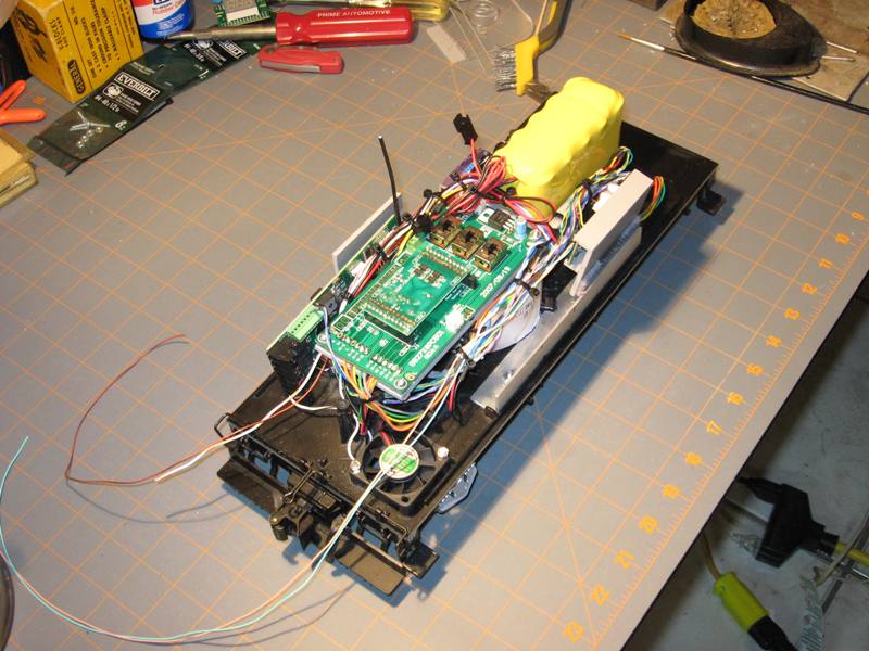
Also, on the intake side, pulling air from the underside of the tender, guarantees it will be in the shade (usually ha ha!) and thus cooler air will be pulled in.

Strategically placed “exit holes” can help also route air where you want flow.

There’s dust everywhere, and it’s not proven to me that air from 1" above the ballast is significantly more dusty than air pulled from 4" above the ballast.

Regards, Greg