Large Scale Central

Major K27 overhaul

How will it affect the performance of the OEM Bachmann tender board if I extend the wiring between the sockets on the tender and the board. I am installing a 5600 mHr LiIon battery and need to relocate this board to make it fit. I am also relocating the speaker as well.

Thanks,

Bob C.

Is this in your K-27?

I installed the same size battery in mine and all I did was cut off one of the posts that held the circuit board.

Ken,

Not sure why, but I tried 16 ways to Christmas to fit that battery with out major butchering but just couldn’t see it. Sooo, out came the tool box. First step was to determine where I wanted the battery to reside. I determined I wanted the ability to remove the battery for charging (if I desired). No matter how I tried, it became necessary to move the speaker back as far as possible. This required removal of the speaker mounting boss on the floor of the tender.

Speaker Mount Cleaned Off

And moved it back as far as I could.

Speaker Relocated

Next I added some 3/4 x 3/4 angle to reinforce the sides, replacing the stiffness the weights added.

Added Reinforcing

I have added some shims under the battery to maintain clearance for the power wires coming up through the floor from the lead truck. The next three pics show the general locations of the components as I plan the layout to be.

Parts Position Top

Parts Position Lefthttp://www.gscalejunkie.com/GeneralPics/K27Mods/PartsPositionLeft.jpg

Parts Position Right

I am not sure precisely how the AirWire and PB11 cards will be mounted yet, still figuring that out. I will NOT use double sticky tape, as I believe that was partly the cause of the failure of the PB9 card - insufficient air flow to maintain temperature.

I am also considering running all interconnections between the tender floor and tender shell through a Sub D electronics connector so I only have one connection to make, and all the wiring will remain neat and tidy. I know, OCD :slight_smile:

Your battery must be a tad bit bigger then mine although it looks like the same pack:

(http://rgsgardenrailroad.com/k27_rcs04a.jpg)

You can see the hole in the circuit board where the screw used to be going into the post I removed. I also don’t install the battery so I can change it out. There’s a charging jack installed on the back end of the tender. All the other stuff I just found places in the tender where it fit with an on/off switch under the coal load.

All my sound cards are mounted on double sided tape. I’ve never had one fail and some are around 15 years old.

What is interesting is I called Rick and got the overall dimensions from him before deciding to go with the 5600 battery, having done some dimension checks and it said it would fit. Best laid plans … and all that.

I will be making a mount for the B’mann board out of some 1/8 ABS. Considering the need to straddle the battery for part of the distance and cantilever the other end I thought the additional thickness would be necessary.

What leads me to believe the double sticky tape might have been the demise of my sound card was that the diodes that self incinerated were squarely in the middle of the tape holding the card to the floor of the tender. No doubt this method has been used for a long time, but I am a once burned, twice shy kinda fella, so I am going back to mechanical mounting. I do need to call both CVP and Phoenis and discuss the ramifications of adding a CPU fan to introduce ambient are into the tender during peak summer days. I am going to guess that if I can read 165 degrees on a brass rail head, a black plastic enclosed tender body just might get close to that with out additional ventilation.

Later,

Bob C.

Engineered the new mount for the main board out of 1/8" ABS plastic I had laying around Didn’t think to take a pic of it alone. Also made a speaker enclosure out of the bottom of a Community Coffee creamer can.

Test Fit Mounting Piece

Got the main board re-mounted and wired in, then did a test fit of the tender shell. OOPPPSSS! The additional bracket for the main board made the stack up too high for the shell. Took it all back off the standoffs, cut .280 off each of the standoffs and remounted everything again. This time it all fit below the tender shell (except the battery pack). Last item completed is I located and mounted the G2 card. I didn’t care for the double stick foam tape cause I can’t work with it easily. I opted for a 1/8" ABS plate epoxied to the aluminum angle and pieces of velcro to hold the card to the ABS.

G2 Mounted

There are three locations on the main board marked ‘R’ and three marked ‘L’. Two are on the sides of the board and picked up the leads from the tender trucks. One each of the R and L pads are on the end of the board connecting to the connector on the floor of the tender for the loco connector. It appears that the side pads are connected together, but not so with the pads on the end of the board. My intent is to place the receiver between the battery/track power and the main board (yes there will be a bridge rectifier on the track power side to maintain polarity). My question is - Do I need to provide power to the R and L pads on the end of the board separately from the side pads or are the connected together else where in the workings of the main board?

Bob, I’m just curious as to why you are keeping the main board if you are using an airwire card? Again, not bashing or anything, just curious.

Also, the PB9 had to black discs (sorry, can’t remember what they were) on the bottom that when double sided tape was attached and the board was moved it would cause damage. Phoenix repairs them for free as it was a design flaw. May be somethign to look into if you haven’t.

Terry

Terry,

Keeping the main board is a flexibility option (plus I don’t want to do all the other re-wiring to get lights working properly). It also makes the loco more salable (my opinion) later should I ever tire of it (not likely).

The thumbnail on the sound card went like this. RLD installed the PB9 card several years ago (Robbie delivered ti to me at the SEGRS 2009 maybe). The card ran for maybe 10-12 hours run time and quit working. When I opened the tender for inspection the burned portion of the double sticky tape was very evident. Took photos, emailed Phoenix pics and back story and asked 'What can you do?" The requested the damaged card for review. A few weeks later I received a new PB11 card. I will praise Phoenix’s customer service on score. And if memory is correct I was told the ‘black discs’ were the surface mounted diodes for voltage control.

This is only part of the total ‘shopping’ of the K. I am also review several old posts on runnability, yours being one I am paying particular attention to. I also had a chat with TOC on the subject and he added a few recommendations I was not aware of. Will also be removing the smoke unit and the fan. In my opinion after installing Rodney’s drive the load on the motor will no longer require the fan. I may try to re-purpose it into the tender for cooling air flow there. That is where the heat is going to be.

Thanks for your input, it is appreciated.

Bob C.

I gotcha. Nice work on the install. Are those 18v batteries you have in there?

Terry

Yep, 18v 5,600 mHr. I figure I should be able to run a full 8 hours at a show or open house. At least that is the game plan anyway.

Thanks for the compliment. More to come a bit later this evening.

Bob C.

A Little more progress today. Fabricated the bracket required to mount the D Sub HD 15 pin socket connector ion the stiffener angle on the floor of the tender. Lots of drilling, cutting (jewelers saw), and filing to get the required shape.

D Sub Bracket

Next I mounted the bracket to the stiffener using Gorilla 2 part epoxy.

Tender Mounted Bracket

Next I wired up almost all of the tender shell switches and plug to the D Sub HD 15 plug connector. I have one SPST switch to acquire at Radio Shack tomorrow to finalize the tender shell mods for the electronics. I still need to cut out part of the front cross member of the shell to allow clearance for the 18V 5,600 mHr batteries from Cordless Renovations. Maybe in a future mod I will try to make my own as others have done. Loco Bill on the Bachmann forum has a quite lengthy thread on doing just that. More to come …

Bob C.

I finally finished up my completed wiring diagram. It is a bit more complex than I want to do in JPGs, so I did a single PDF. Here it is:

http://www.gscalejunkie.com/GeneralPics/K27Mods/K27_Wiring_Diagram_R2.pdf

I hope this will help others with similar ideas.

Bob C.

Edit to update the schematic PDF based on conversations with Phoenix on the functionality of the PB11 card.

Ran by Radio Shack on the way home after work and found the SPST toggle I needed to complete the tender shell side of the mods. I now declare the shell complete.

Outside of shell

The switches/plugs from left to right are: 1) Phoenix Sound on/off, 2) Track power / Battery power, 3) Phoenix programming jack, 4) Phoenix Sound volume switch. RLD Hobbies installed 3 and 4, I added 1 and 2.

Inside tender shell

I was not certain of the wiring for the PB11 Phoenix sound card using the transistor and Bachmann boards, so I sent off a copy of my schematic with a request for a review. John Weaver of Phoenix Sound responded promptly this morning with a positive answer along with a couple recommendations. Now I need to squeeze more stuff in there. Sheeeshhh…

I did finally figure out how to mount my PB11 with out the use of double sticky tape. Thanks to reviewing a article on the OVGRS site, I used a similar method to one a member there used. Thanks OVGRS for the inspiration. Some more of the 1/8" ABS plastic, my table saw and shazam …

Phoenix mount

That is it for now. I need to order some parts from Mouser Electronics and get the voltage regulator John recommended built and mounted before I can finalize the tender wiring and button up the tender.

Nice work Bob. I like your use of the DB-9 to allow the shell to be completely removed.

DB HD15, but whose counting. It was the concept I was trying to portray. I really needed a few more connections, but didn’t want to go the the next size up DB HD. I still have a bunch of work to do to completion. Keep watching :slight_smile:

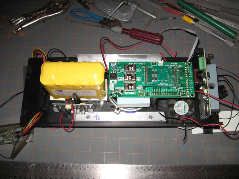
Being as my electronics didn’t arrive in the mail today as they weer supposed to, I moved on to the locomotive modifications. The four major mods to be done are:

  1. Lock axle #1 and #4 to near ‘0’ side play

  2. Install Rodney’s gear reduction drive

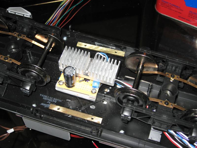
  3. Remove the cooling fan (don’t think I am gonna need it)

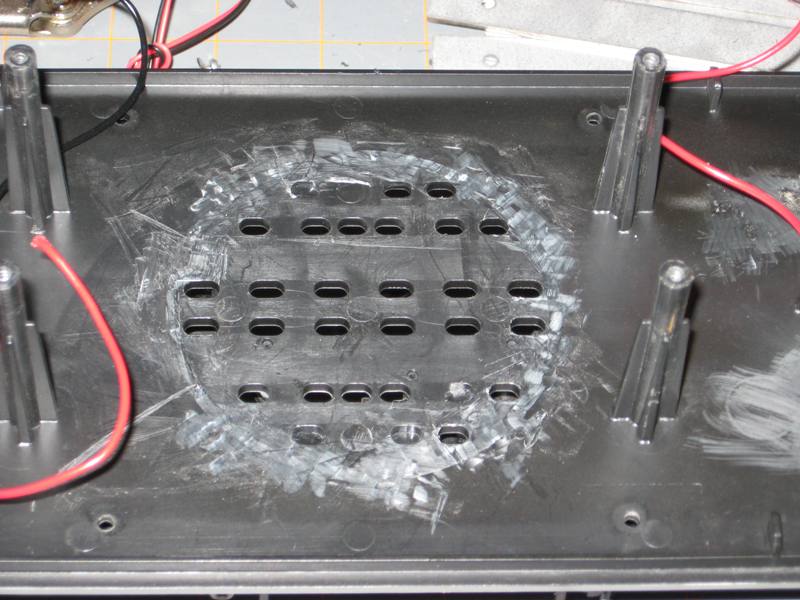
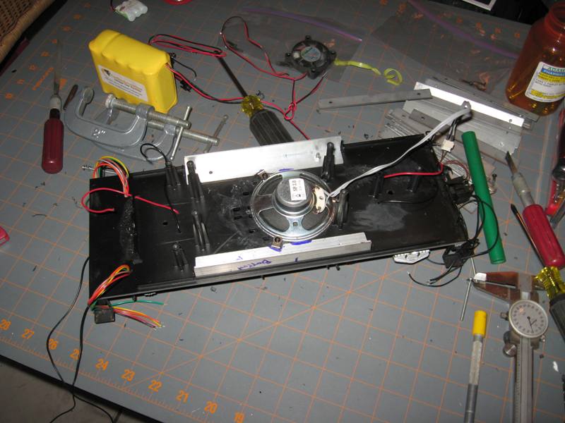
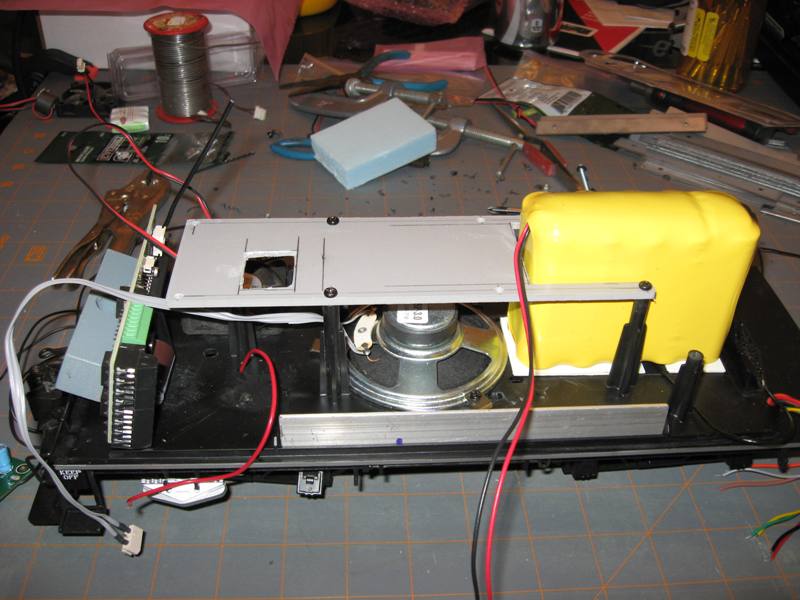
  4. Remove the smoke unit to make way for a speaker and possibly more weight in the front.

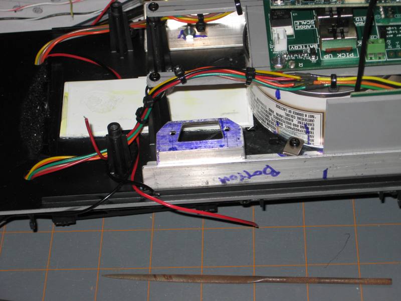
Please excuse the pictures. I got in a rush to get it done and forgot to take pictures during dis-assembly. I think the shots during re-assembly, shown backward will get the idea across and allow me to do some explanation. I borrowed a trick someone else on the forum commented about and used the original styrofoam packaging as a work stand.

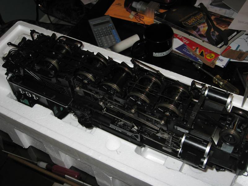
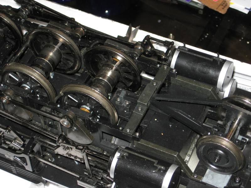
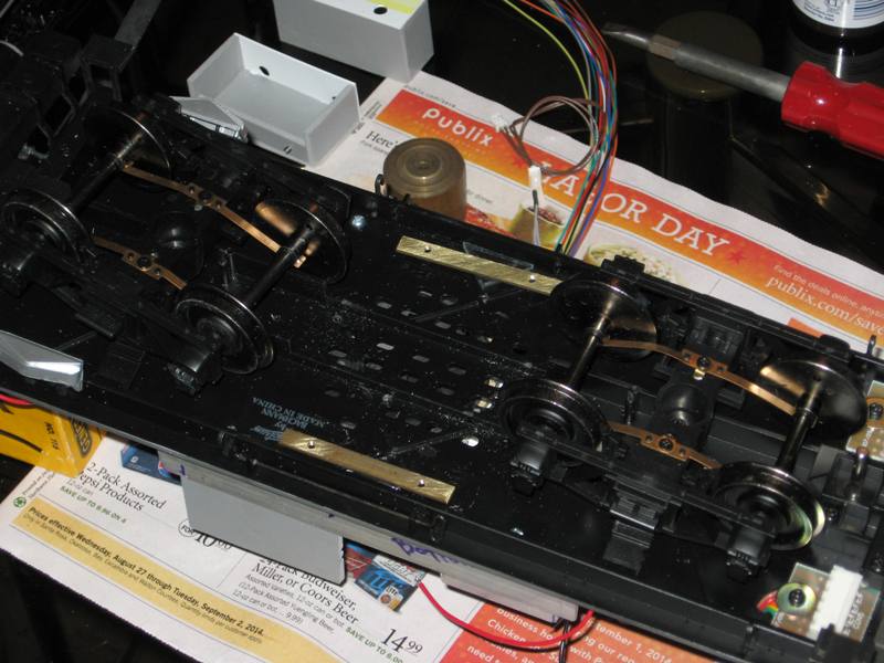
First task is to remove the retaining plates holding the journals in place. As I started to dis-assemble these I notices that several of the screws were no longer tight, but has begun to loosen and work their way out. Note to self, check these screws periodically.There are 5 screws in the front retainer and 4 in the rear retainer.

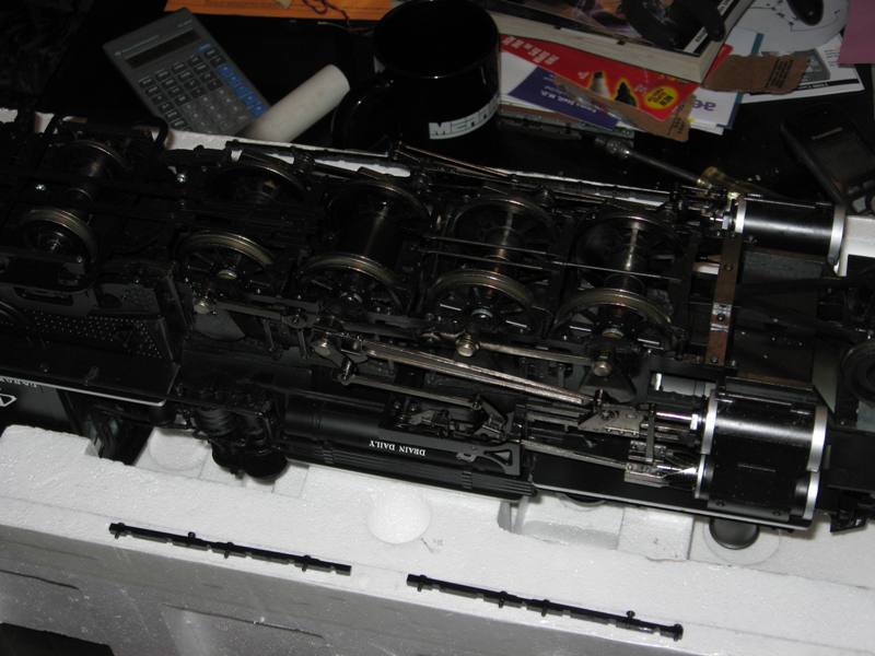
Next task is to carefully pick up and remove the brake rigging that goes down the center of the locomotive. The front rigging will have the brakes for axles 1, 2 and 3. The rear rigging will cover axle 4, and there will be a single screw holding it in place, centered on the rear of the rigging.

Once the brake rigging is removed and out of the way, remove the screws the attach the rods to the counterweights. These are a 9/32" wrench of socket. You will need to rotate the drive about 1/4 turn to be able to remove the screws side to side. Once removed you will be able slide the rods off the counterweight and be able to lift the axle out of the frame. Do this SLOWLY to make sure the suspension springs and electrical pickup springs (located inboard) remain in their locations. I recommend doing one axle at a time to assure parts don’t get crossed up.

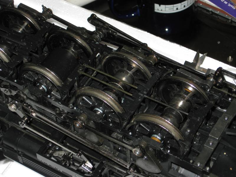
In the photo below, I show the 4 springs that make up the suspension for each axle. Two important items to note. 1) According to TOC (Curmudgeon) all four springs are required to make the suspension work properly, so even if you don’t use track power keep these in place. 2) Just like all the other moving parts of the locomotive, lubricate these periodically.

While I had my loco open for surgery, I removed one of the suspension springs under a journal and did some measurements. For those interested, the spring is 0.103" OD, 0.320" free length, and .013" wire diameter. I have found some slightly heavier springs from Century Spring Co. that I think will work to remove the ‘butt drag’ so many notice. I went to order them online, but they require a $40.00 minimum order so that didn’t happen today. I do have a plan…

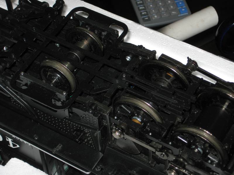
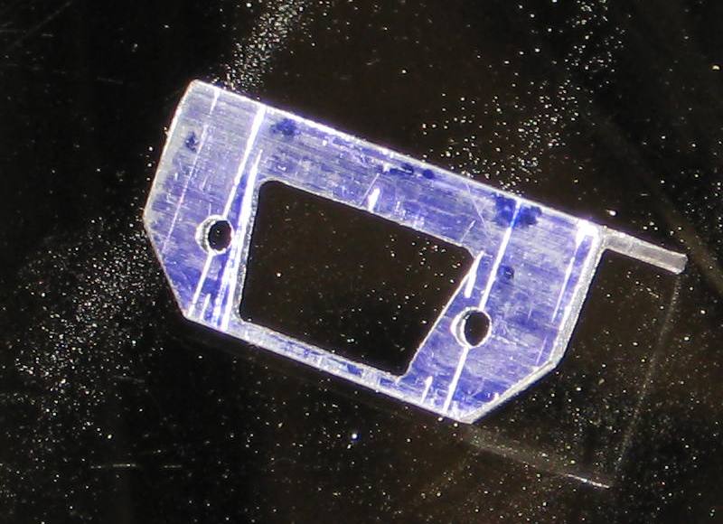
The spacers I made for my K are from a piece of tubing I had in my brass bits box, .375" OD x .250" ID. After a couple of false starts I ended up cuting .200" LG (+/- the thickness of my razor saw) and came out with just about ‘0’ side play. The picture below shows the ‘exploded’ axle on one end. From left to right - axle, new spacer, OEM spring, plastic collar, journal/bearing, and conter weight. Do what you will with the spring, removal is the purpose of the exercise. First install the spacer, followed by the plastic collar. Here is where the ID of the tube is important. The collar fits perfectly inside the .250" ID tube. Follow this with the Journal/bearing and lastly the counter weight. There is a loose fit between the axle and the electrical pick up segments. Keep this loose fit. If the fit is too tight it will make the engine ‘waddle’.

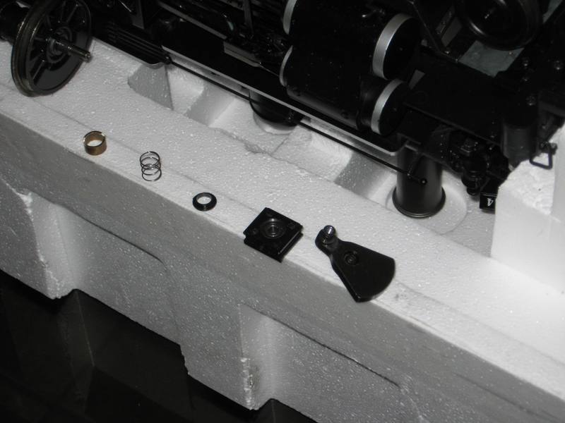
Re-assembly is the opposite of the dis-assembly with the following caveat. The is a small ‘tit’ on the top of the journal/bearing that fits into the center of the spring. Be sure of the orientation of the journal/bearing when re-installing it into the frame so the journal/bearing is located properly.

The length of the spacer I provided is for reference only as this is what fit my K27. You may need to adjust this a bit for yours.

I didn’t bother to photograph the installation of Rodney’s drive as I seem to remember he had an instruction sheet on he web site. Removing the fan and smoke unit are sort of a no brainer. The only thing I did on the smoke unit was to slip some heat shrink over the eye connections on the ends of the power leads.

Very nicely done, Bob… The mount for the PB11 is excellent… Will hold it tight and allow “breathing” room for air to get around and under… Well done… Thumbs upThumbs upThumbs upThumbs upThumbs up

Bob,

looking for springs? try McMaster Carr. you might be surprised at what you find. stock drive products and W.M.Berg as well. online ordering for all three. unfortunately you still get the bite on shipping no matter who you use.

Al P.

It has been a bit since my last installment, so I thought I would bring you up to date. One of the things I have been working on is the Power Control board that will control track power to the loco providing a regulated maximum voltage of 16.5 volts to the AirWire G2 decoder. This will also provide a reduced 12 volt supply for a small cooling fan I plan on getting inside the tender.

A top and bottom view of the board mounted on a heat sink modified from a computer CPU heat sink. Lots of cutting and filing. Here are a couple of pics of the board.

Power Board Bottom

Power Board Top

I have also started working on mounting a couple of ‘tool boxes’ to help hide the electronics. I started by adding a couple of brass bars tapped to #4-40 to mount the boxes. I added a filler piece below the brass bar and epoxied the bunch to the floor.

Tapping Bar

These will mount the tool boxes

Tool Boxes

Finally got the control board mounted on the bottom of the tender floor. This picture does not show it but I also routed the wiring up through two existing holes in the floor.

Electronics Mounted on Tender

And last for this posting is a shot showing the ground clearance of the electronics. Not much. The tool boxes will be approximately the same clearance.

Ground Clearance

Next comes the interconnection of all the wiring between all the devices. I will try to take staged pics as I go, following my diagram. Note: I have revised the wiring diagram based on my conversations with Phoenix, a new PDF has replaced the original.

Hey, those fins aren’t lined up the right way! :wink: