Large Scale Central

Improving the Tracking on AristoCraft Streamliners

I have a trio of the AristoCraft Streamliners and love the way they look. I’ve even modified one adding a drum head and rear flashing lighting that stays on when the engine comes to a stop.

But what I don’t love is the way they continually derail on me on the slightest trackwork imperfections. I know that improvement may be had by changing the springs, I think that there is an inherent flaw in the truck/body interface that exacerbates the problem.

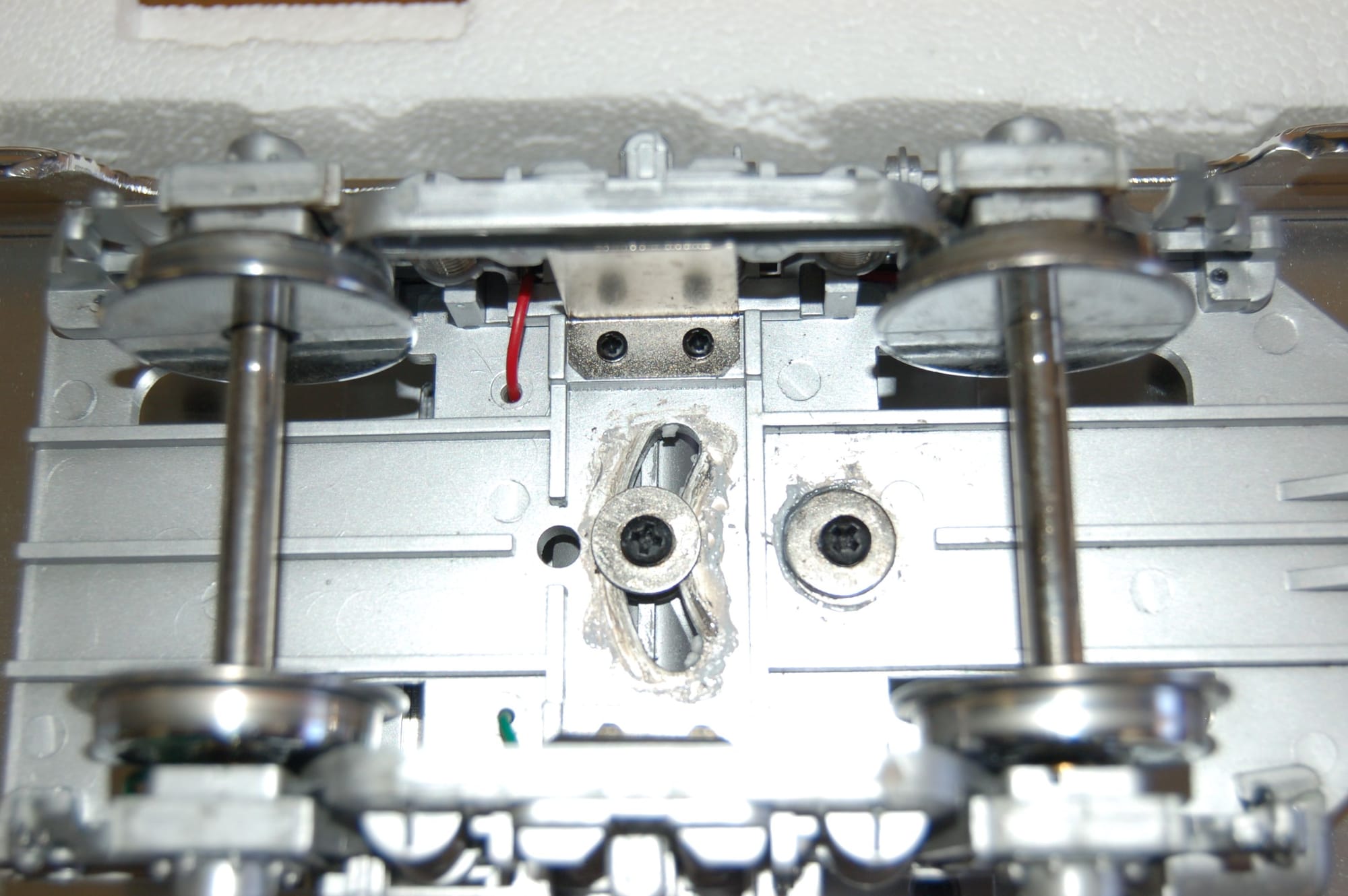
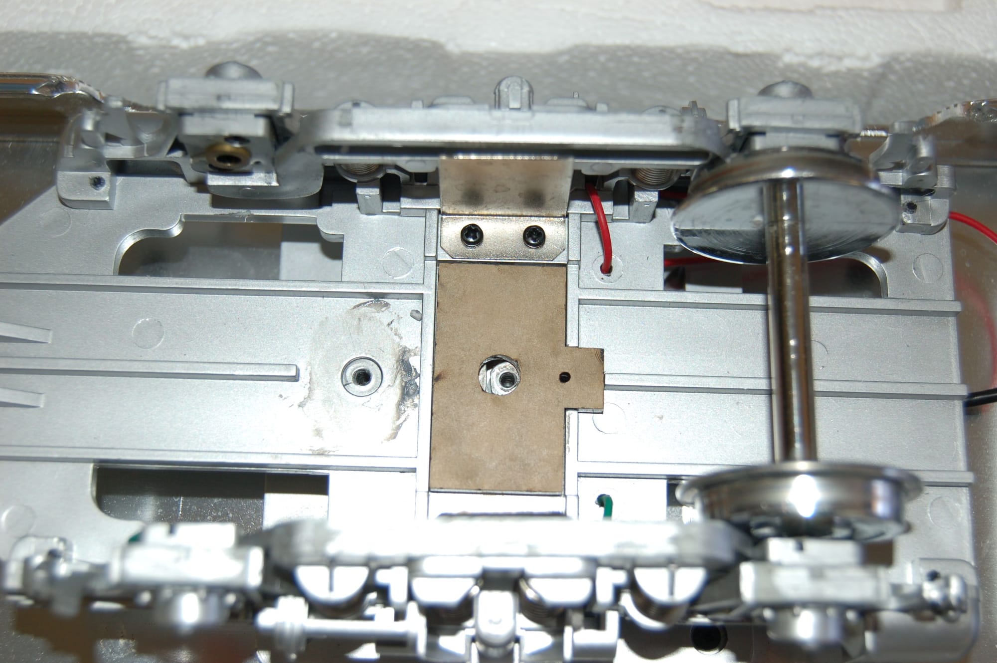
I feel that the problem lies in the fact that truck pivot point does not lies midway between the axles, but rather just behind the front axle. The result is that changes in the position of the coupler from side to side that also pull the near axle over are “amplified” to the far axle forcing it further out in a curve making it want to/more prone to jump the rail head.

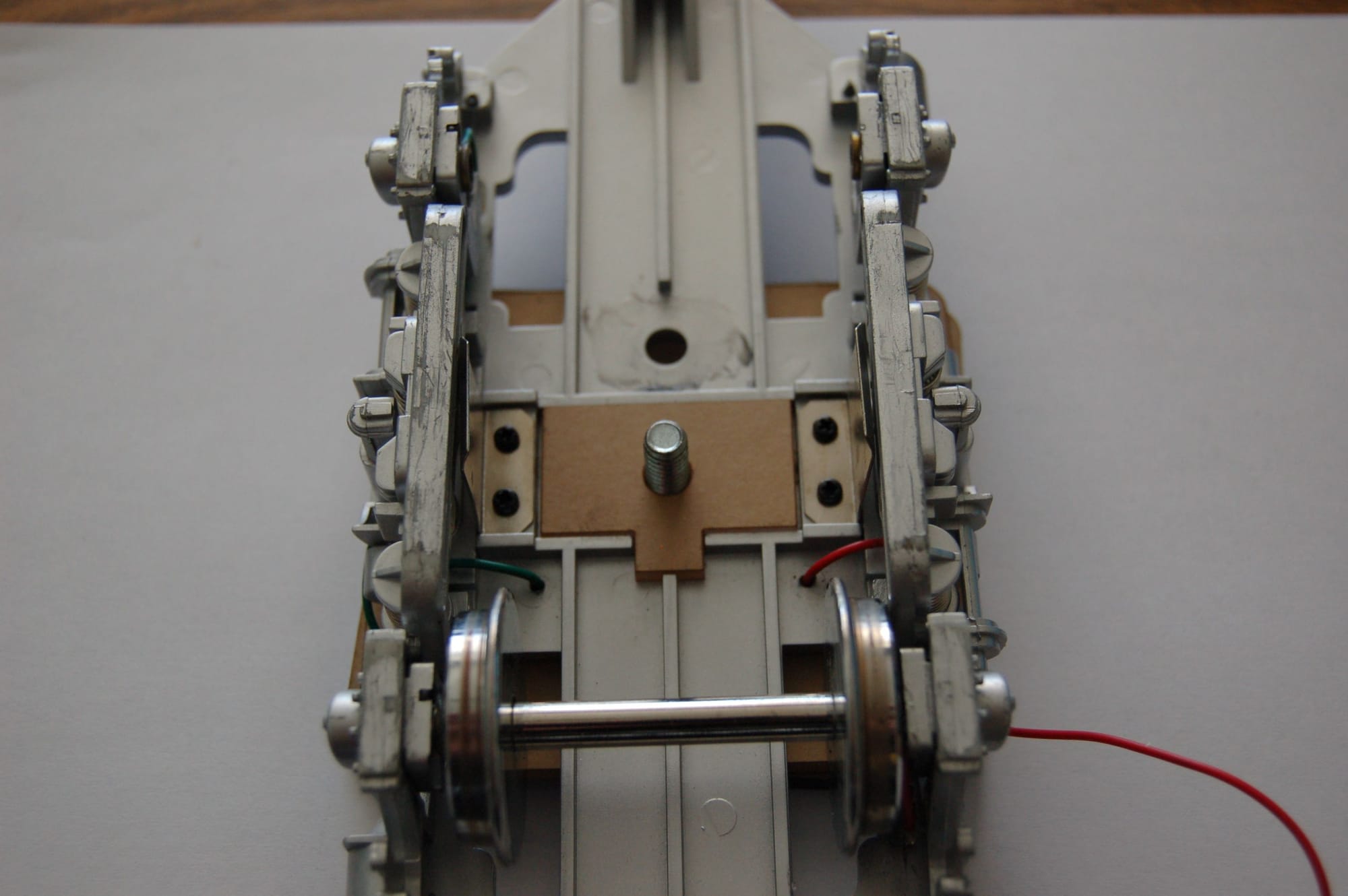
I cut a filler plate on the laser that will place the central pivot point where the rear “slide” point now resides, midway between the axles. Then I’ll design new bolsters with will capture a 1/4"-20 screw for use as the new pivot point. These will be done in three parts.

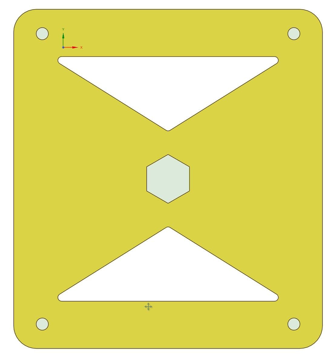
The lower bolster (closer to the body) plate will have about the same shape as the existing bolsters with the four screw mounting holes to meet the existing holes in the body. The center will be cut as a hexagon to contain a 1/4"-20 bolt head.

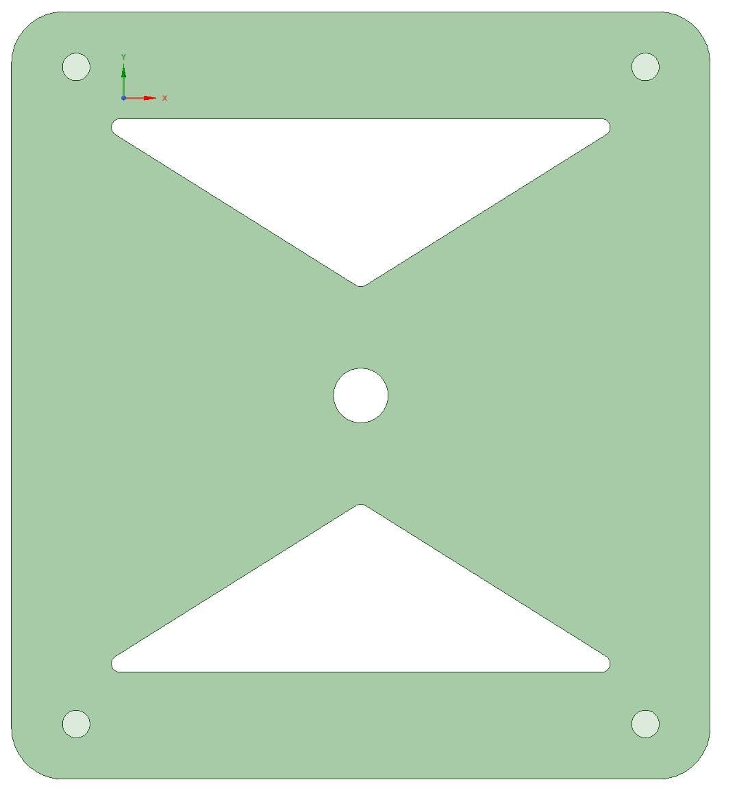
An upper bolster plate (further from the body) will be of similar except that the center hole will be 1/4" to let the bolt threads pass through.

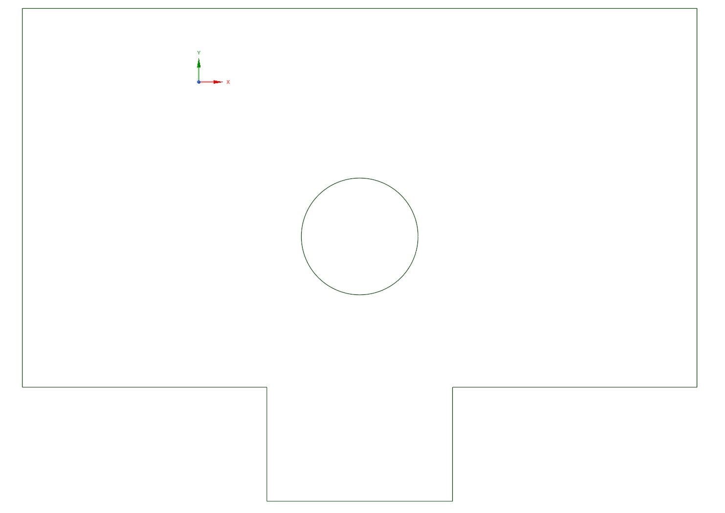
A round disk will then be placed over the bolt to allow the trucks to rock and will compensate for the portions of the truck that would hit the bolsters.

Hopefully this will improve tracking, but if not, no damage done.

http://www.girr.org/girr/tips/tips3/streamliner_tips.html

might help(https://www.largescalecentral.com/externals/tinymce/plugins/emoticons/img/smiley-cool.gif)

It might be noted that GLX Scale models has a kit for making all the improvements involved in this thread. I have converted at least 6 cars using the kit, and can attest to the quality of the parts. It includes the conversion to body mounted Kadee Couplers.

www.glxscale models.com

Fred Mills. scalemodels.com

It might be noted that GLX Scale models has a kit for making all the improvements involved in this thread. I have converted at least 6 cars using the kit, and can attest to the quality of the parts. It includes the conversion to body mounted Kadee Couplers. They have had this kit available for at least 3 years.

www.glxscale models.com

Fred Mills.

David Marconi,FOGCH said:

http://www.girr.org/girr/tips/tips3/streamliner_tips.html

might help(https://www.largescalecentral.com/externals/tinymce/plugins/emoticons/img/smiley-cool.gif)

Thanks, I hadn’t seen that in a while. It is nice that George has saved me from performing the measurements for the bolsters. Now I can proceed without taking anything apart (for measurements) until the pieces are ready for install.

BTW, the pics of the LGB equipment were taken here at the Tortoise & Lizards Bash on its inaugural run day.

Fred Mills. said:

It might be noted that GLX Scale models has a kit for making all the improvements involved in this thread. I have converted at least 6 cars using the kit, and can attest to the quality of the parts. It includes the conversion to body mounted Kadee Couplers. They have had this kit available for at least 3 years.

www.glxscale models.com

Fred Mills.

Thanks. At $89 each kit plus shipping (one axle or two???), that is more than I paid for each streamliner. I’ll continue with my idea which just costs me some time. Besides, I think mine is the only one that will put the bolster mount half way between the axles and it seems like that has to work better.

Todd Brody said:

David Marconi,FOGCH said:

http://www.girr.org/girr/tips/tips3/streamliner_tips.html

might help(https://www.largescalecentral.com/externals/tinymce/plugins/emoticons/img/smiley-cool.gif)

Thanks, I hadn’t seen that in a while. It is nice that George has saved me from performing the measurements for the bolsters. Now I can proceed without taking anything apart (for measurements) until the pieces are ready for install.

BTW, the pics of the LGB equipment were taken here at the Tortoise & Lizards Bash on its inaugural run day.

Remembered the measurements were on there, was the main reason I thought it might help. changing the mount screw does help. I’ll take a closer look at the LGB then.

Todd Brody said:

… The result is that changes in the position of the coupler from side to side that also pull the near axle over are “amplified” to the far axle forcing it further out in a curve making it want to/more prone to jump the rail head.

from your words i deduct, the couplers are truck mounted.

if that is so, you might consider to save a lot of work, by simply giving the connection between truck and couplers some sideways playway. (that should eliminate the sideways force on the far axle)

Korm Kormsen said:

Todd Brody said:

… The result is that changes in the position of the coupler from side to side that also pull the near axle over are “amplified” to the far axle forcing it further out in a curve making it want to/more prone to jump the rail head.

from your words i deduct, the couplers are truck mounted.

if that is so, you might consider to save a lot of work, by simply giving the connection between truck and couplers some sideways playway. (that should eliminate the sideways force on the far axle)

Been ther done that. Couplers (truck mounted Kadees) are free to pivot almost 120 degrees in either direction about their mounting screws. But even if the coupler is allowed to pivot, the “tangs” (mounting shafts) are pushed outwards in a turn and this still puts a torque on the truck.

Tod;

The major problems with all the trucks , be they 6 wheeled, or four wheeled, on all the Aristo heavy-weights, and stream liners, was the way they the trucks were mounted; OFF CENTRE. All this just to try to lesson the swing of those bloody, truck mounted couplers. Then of course the 6 wheeled trucks having ridged centre axels. Basically the whole set-up was engineered by an idiot. (IMO)

BTW, the GLX kit includes the solution for the offset mounting of the stream-lined 2 axel trucks which you are probably, unknowingly copying.

Body mounting Kadee couplers on these cars is a major step in closer coupling of these cars, making them almost appear to look like the prototype, and will allow for minimum of 5 foot RADIUS curves.

I’m not going to get in a no-winner argument, over which coupler is best, but I do admit to favoring the Kadees.

BTW I do not in any way get any rewards for promoting GLX. All I know is that their kits for these cars solve all the problems, except the poorly designed 6 wheel trucks, on the heavy-weights.

Believe it or not, just out of frustration, and to prove a point…although they are NOT the proper truck for them. I moved the body bolsters on the heavy-weights, and made them accept “Believe it or not” Bachman passenger trucks. The cars now, with body mounted Kadees, are VERY dependable, and now give no trouble at all. Proving that the 6 wheeled trucks were the major problem.

No, we don’t run our trains on a display type railroad, with few, if any switches, and 29 foot diameter curves. We operate and have multitudes of switches, primarily Aristo Wide radius, and a minimum of 10 Diameter curves, featuring up to 2-3% grades.

Good fortune in trying to solve your passenger car problems. Your experiences, and solutions are worth reading about. Thank you.

Fred Mills

Thanks Fred,

I also have heavyweights and replaced the 6-wheel truck on the dining car to the 4-wheel version and my heavyweights with shortened couplers operate without derailment through 8’ diameter curves as well as back-to-back LGB 1600 turnouts.

All of my curves are between 8 and 10 foot diameter, and the streamliners have their biggest problem though the “S” curve that is on a slope. If anything gets out of “kilter” even a bit, they will derail.

The GLX site does not appear to show the bolster mount on their site, but I did find a pic of what I think they use. Do they also add a filler piece to the to turn the curved hole to a round hole on the trucks? Is there an illustration of all of the components preferably assembled?

BTW, when doing my conversion, (i.e., changing the rear curved hole to a round hole and letting the truck pivot about this new point), still does not set the hole in the exact center between the trucks (assuming the rectangular area is centered), but rather about 0.12" behind the center as opposed to about 0.85" in front of the center which is how they come.

To get to the exact center of the truck would require that the slotted (curved) hole be drilled forward about 0.12 inch at its center and the bolster would need to have it’s central point moved forward by this same amount. Otherwise the movement of the truck (fore/aft) would interfere with the wheel cutouts sitelines, though 0.12" of movement may not be noticable.

OK, these are the CAD files for how I propose to do it. As an added benefit, it will be much stronger than the original plastic mounting posts, several of which show cracks. My mounting post is a 1/4"-20 bolt.

This is the bolster plate closest to the body. It will be cut from ~0.175" thick acrylic. The head of a 1/4"-20 bolt is ~0.155" thick so the acrylic is a hair thicker than the bolt head and will retain the bolt from turning. The cutouts allow for the wires to pass through.

Next is the top bolster plate that retains the bolt. It is like the lower plate except that the hole is 1/4" round and the piece of acrylic is ~0.125" thick.

Next out is an acrylic washer that is 0.5" diameter with a 1/4" hole in the center. This lets the truck rock and the acrylic is just a bit thicker than the detail on the trucks that sticks up and would interfer with the bolster plate allowing the necessary clearance. This is also ~0.125" thick.

I am assuming that the actual center of the “plastic square” of the trucks between the axles is centered between the axles, but have never measure to confirm. Anyway, the rear post of the original bolsters is not centerd in the square, but about 0.12" rearward towards the center of the railcar. But it is much closer to the centerline than the existing pivot point (~0.85" forward of the centerline of the trucks) and will be used for this exercize. This is an acrylic plate that nestles into the coupler and turns the slotted hole into a round hole in the proper location.

Finally, a washer and 1/4"-20 nut will retain the assembly. The nut will actually add a bit of weight at a very low center of gravity which is a good thing. I’ve actually cut one of these plates on the laser and the fit is perfect. But I did have the hole centrally mounted in the larger rectangle and it did not line up with the post being off about 0.12". It is the midway point of the slotted opening that is at the center of the trucks. (http://www.largescalecentral.com/externals/tinymce/plugins/emoticons/img/smiley-wink.gif)

Based on the thickness of the acrylic, this modification will lower the body about 1/8". I run these behind AristoCraft FA/FBs and didn’t want to lower the bodies a bunch because the engines are already just a bit taller than with the existing mounts.

For those unfamiliar with the workings of the trucks, I present the following pictures:

Note that the truck pivots about the screw on the screw tower to the right, while the center of the truck is actually about where the the screw tower on the left is located. The actual center between the two axles lies at the midway point on either side along the swept curve.

So, if we torque the truck about its pivot point, the rear axle sweeps a much bigger circle than the front axle sweeps, which is in the opposite direction. Ideally, these should be the same (i.e., symmetrical about the pivot point), at least in my mind.

So rather than pivot about the front tower, it is much closer to the centerline to pivot about the rear tower, which is almost right between the axles.

So, to use this more central post (or a replacement for it), we need to get rid of the outter post because it will interfere with the truck’s swing. And, we need a way to keep the truck swinging around this central post, rather than sliding off to a side as the curves slots would allow for. The curved slots are perfectly sized to accomodate a 1/4" bolt.

A filler panel that nestles right into the design of the trucks should work like a charm. Here you see my prototype, and my discovery that the post is not exactly centered between the axles. The next filler panel will compensate for this by moving the hole to the proper location (~0.1" rearward from shown). BTW, as I noted, you can see a crack in the tower. This is common and I have a few like this.

My answer to your two questions is YES. Also included are the needed pieces to replace the two small connecting plates that connect the body end pieces to the main body, and are the base for the body mount Kadee couplers.

Basically all your designing and work for the Stream-Lined cars/trucks, has been accomplished, already, and tested by GLX.

Oh, BTW the needed lowering of the cars is also accomplished by the GLX kit.

Fred Mills

As I said, I would like to see their offering, but don’t see it broken down. All they show is a pic of the streamliner.

…And there is the matter of cost. This costs me nothing as I already have the acrylic and bolts, and I already pay to use of the laser regardless if I use it or not. Additionally, if it works, I get a sense of accomplishment that is just not attainable buying a ready-made product.

Tod;

As long as you are happy, and generously sharing your experiences with others…That’s what counts…

Fred Mills

Tod;

As long as you are happy, and generously sharing your experiences with others…That’s what counts…

Fred Mills

Looks like I may have found a picture and it looks like they are doing almost exacly what I propose including the slight offset from center. (http://www.largescalecentral.com/externals/tinymce/plugins/emoticons/img/smiley-wink.gif)

I had never even heard of these guys let alone known about this. I guess it’s true that GMTA! (http://www.largescalecentral.com/externals/tinymce/plugins/emoticons/img/smiley-laughing.gif)

The following, “vignette” includes what I had done to mitigate the Aristo fluted side Streamliners:
"Aristo Streamliners - Lowering & Body Mounting Kadee 907 Centerset Couplers"

The train with lowered cars and body mounted Kadee centerset couplers can be seen in a video done on May 6, 2015 (It’s best seen on YouTube for the “show more” comments):
Union Pacific 7 car Streamliner train operating on outdoor layout.
Link:
https://youtu.be/3LjYOVJv2fc

-Ted

Thanks Ted.

I was able to get to the workshop today to use the laser. These parts are thin and to do all three railcars with one set spare took under an hour to cut. The bodies will actually be lowered 0.15-0.2" from the standard mount and allow more forward/aft rock as well as side to side rock, which is non-existant with the stock set-up. And, unlike most of the other conversions, the trucks will now pivot much closer to their centerlines.