How does Aristo track maintain proper gauge? Inquiring minds want to know! 
Just measured a piece of their track. Tolerance spread from 44.60mm to 45.20mm No, I don’t know which standards apply to their products.
I either take out the screws underneath, or leave them in. If I am bending a piece, they come out. If I’ve slid a piece of rail into the tie strip (even an original piece removed for whatever reason), they may or may not be replaced. Either way, the fishplates hold it in gauge well enough for my equipment to operate without derailing.
I was told the screw on the bottom hold the gauge but like Todd I removed all the screws when bending the track and for the most part the gauge is fine.
A little tight, NMRA specs are 44.85 mm to 45.54 mm.
G1MRA is 45mm specified as plus 0 and minus 0.5 mm.
So depends on whose standard you want to use, but out of spec on either one... I've seen a lot worse. (like at my house ;-) )
Greg
I made a track gauge to the G1MRA specs, and I find that the Aristo track tends to be a bit tight, especially on some of my curves. Most of the track doesn’t have the screws through the ties into the rails. I have the Aristo stainless track with the USA style ties. I am not sure how that compares to the “Euro” ties for gauge.
In a few places, I notice that my LGB locos will hop just a little. They hop because the gauge is so tight hat the wheel flanges, on both sides of the loco, are contacting the rails and it pushes the loco up. But this is only in a few places. My other equipment doesn’t do this.
The worst section of track for gauge (both under and over gauge) I have replaced this spring. The problem I had there was self induced. I had used some small scrap pieces to finish the loop. and I wasn’t using a rail-bender at the time. So my rails weren’t bent parallel to each other. This spring I bent a full 5 foot long section to replace those bits and pieces.
The Aristo track is a bit sloppy on its gauge, but I don’t have any serious issues because of it. In fact, I believe that track gauge slop is kind of expected in model trains, that’s why the wheel treads are so darn wide. If the slop wasn’t expected, then we would be using fine-scale wheels on our layouts. Indecently, I have found the same to be true in HO. I have put an NMRA HO track gauge on a few different brands of track, and the track is manufactured too wide. And HO wheel tread is also way over scale thickness, just like our large scale wheel treads.
One of the major issues with gauge, wheels, etc. is smooth operation and no derailments through switches.
Quite often, manufacturers make the back to back and the wheel gauge too narrow.
For years this has been compensated by sloppier tolerances in the wing rails and the guard rails.
Unfortunately, this makes switches less reliable.
When you attempt to “fix” the switches by using tighter tolerances (meeting NMRA specs) then you find that the improper back to back and bad wheel gauge causes issues.
Fix the wheels, and magically, everything works much better.
But now you may look askance at tight track gauge, like you experienced with your LGB loco, and the now infamous wheel setups in the Aristo Consolidation.
There’s more to the equation, but when everything meets NMRA specs then everything works much better. I can back a 45 car train through any of my Aristo switches without a hitch.
Sure, not everyone runs 45 car trains, but this makes even short trains run better.
I can leave a 45 car train running up 3.4% grades and down 5.5% grades while I go to home depot and not worry.
So, I’m a firm believer in standards (that make sense).
Greg
Greg, I agree. I re-gauged the wheels on my cars to spec and many of the issues I originally had on my railroad went away. It would be nice if track and wheels were to spec (the same specifications) from all the manufacturers. That would solve a lot of issues.
Any new piece of rolling stock goes through my shop before it ever gets onto the track. I upgrade to properly gauged metal wheels, or check and re-gauge the wheels if the car came with metal wheels. I believe this simple step would eliminate a lot of frustration for may model railroaders, in any scale. I was surprised that so many replacement metal wheels were so far out of gauge right out of the package. But I have noticed that the latest batches of wheels that I have purchased, have either been properly gauged, or just slightly over-gauge. So the manufacturers seam to be getting better at properly gauging their wheels.
And lets not talk about my shelf queen. The consolidation sure is pretty though.
Either “nicely” or “poorly,” depending who you ask.
Tom, I agree, or disagree. 
I run Aristo track (mostly stainless, some brass all American style) and would like to achieve better reliability. I don’t do roundy-round and don’t need my trains to keep running while I run off to the store, but it would be nice to never have derailments that weren’t a fault of the crew. I’ve come pretty close to achieving this, but still have a few problem areas that need work.
All my SS track began life as 5 foot straights. Sections that have been curved were removed from the ties for bending and only a few screws put back. Straights are unmodified from the factory. As long as my side-to-side is fairly level and there are no sharp vertical curves; I have no issues with the track whatsoever - it just works. Switches are another story.
Early on I came up with my own back-to-back wheel standard. G1MA recommends 1.575" but I chose a slightly tighter 1.565" which seemed to work better with the 1:24 stock on R1 curves and switches that I started with. Now that I run mostly 1:20 and a little 1:29 maybe I should re-think that standard.
99% of my track problems are with the Aristo Wide (10Ft) switches. I’ve tried many of the published fixes, but either I’m not doing it right or my .01" difference in back-to-back is the problem. I can not get most of my 1:20 stock to run through the facing point diverging route on an Aristo Wide switch without picking the points and derailing.
Aristo’s “sloppy” gauge doesn’t really seem to be a problem. If I could just get my “Wide” switches to function correctly then I can call my track reliable.
After 10 years with Aristo Stainless track, my answer here is how does any track maintain gauge. I have never had a problem with derailments due to gauge variations with this track. My derailments are mostly caused by larger rocks from my yard, getting in between the rails. But never a gauge problem.
Jon Radder said:
I can not get most of my 1:20 stock to run through the facing point diverging route on an Aristo Wide switch without picking the points and derailing.
Aristo’s “sloppy” gauge doesn’t really seem to be a problem. If I could just get my “Wide” switches to function correctly then I can call my track reliable.
Have you tried the bent strip of brass that I first came up with? It is the only thing that keeps my heavyweights and streamliners from picking the points as you mention.
Todd - If you are talking about tightening up the gap in the guard rails, then yes. If not, please explain or point me to the info.
Well, the pieces of the NMRA standard all work together. The target is 1.575 +.002 and minus .018, so you are within spec, but your “drift” should manifest itself in needing wider flangeways in the guard and wing rails in switches.
In my personal experience, the switches are the main focus of reliability, and the frogs are already sloppy, so where I can “tighten” the flangeway widths, then I have experienced more control of how the wheels track through the frog, and less derailments, less dropping into the frog, less frog wear.
What I would do is take a switch, and 2 wheelsets, one gauged to your standard, the other to the NMRA target of 1.575 and see how it rolls through the frog, closely observing the extremes of motion allowed by the guard rails and wing rails.
The guard rails are easiest to modify, move the rail or shim it, while the wing rails are often cast in.
When I played with wheels and switches like this, I saw so much opportunity to derail, it convinced me to go almost “paranoid” on the specs, setting each wheelset to exactly 1.575 (of course that does not take into consideration variations in flange thickness)
Anyway, doing the visual experiments and seeing how switches, and their components really worked, I learned a lot. Of course I read a lot also, and many of the early pioneers in building switches, like Grant of Outback (do I have that right?) really helped.
Regards, Greg
Jon Radder said:
Todd - If you are talking about tightening up the gap in the guard rails, then yes. If not, please explain or point me to the info.
Jon, I use a piece of thin brass strip that I bend around the end of the guard rail. This “bows” the brass toward the outer rail first guiding then pinning the wheel in place on the outer rail. George Schreyer has a picture of it on his web site (and gives me credit), but that link is not working for me, though some of his other of his links still do.
http://www.girr.org/girr/tips/tips1/lgb_1600.html
I think that I recall that Greg also includes a picture of it on his site, but no mention of the inventor.
Thanks Todd.
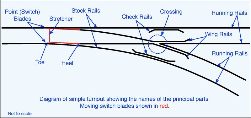
So everyone is on the same page I’ll post a diagram that has most of the components correctly named except the frog is marked Crossing. The Check Rails are also commonly referred to as guard rails…
(http://lsc.cvsry.com/post4/SwitchDiagram800.JPG)
Todd, your fix keeps wheels from picking the frog point. My problem is picking the movable switch points in red. On a switch aligned exactly as shown above, if I approach from the left, some wheel sets will pick the upper red point and travel down the straight route while the previous car correctly took the diverging (bottom) route. This will pull both cars off the rails if you don’t run extremely slow and watch every wheel cross the point and stopping when one takes the wrong path.
Greg - Thanks for your response. Good suggestion on trying a test of wheels set at 1.575"
I have attempted Ted’s point fix as posted on your website. So far, it’s not working for me. I’m afraid to grind too much. Shimming the Check Rails with .020 styrene does make then a bit too too tight for some of my thicker flange wheels. I know that this is a solvable problem. I just have to keep at it.
Jon Radder said:
Thanks Todd.
So everyone is on the same page I’ll post a diagram that has most of the components correctly named except the frog is marked Crossing. The Check Rails are also commonly referred to as guard rails…
(http://lsc.cvsry.com/post4/SwitchDiagram800.JPG)
Todd, your fix keeps wheels from picking the frog point. My problem is picking the movable switch points in red. On a switch aligned exactly as shown above, if I approach from the left, some wheel sets will pick the upper red point and travel down the straight route while the previous car correctly took the diverging (bottom) route. This will pull both cars off the rails if you don’t run extremely slow and watch every wheel cross the point and stopping when one takes the wrong path.
Greg - Thanks for your response. Good suggestion on trying a test of wheels set at 1.575"
I have attempted Ted’s point fix as posted on your website. So far, it’s not working for me. I’m afraid to grind too much. Shimming the Check Rails with .020 styrene does make then a bit too too tight for some of my thicker flange wheels. I know that this is a solvable problem. I just have to keep at it.
John, what kind of couplers do you use and how are they mounted? What is the track work adjacent to the turnout?
When I came up with the brass insert, it was because I had a 1600 LGB turnout to the right and the straight route took a 10’ diameter curve to the left for one AristoCraft sectional piece, then curving back to the right. My heavyweights would continually pick the point to the right, even when the points and engine went straight.
What was happening was that as the engine went off to the left after the turnout, it pushes its coupler, and that of the heavyweight behind it toward the right and this makes the truck jump the point toward the right, in the wrong direction, causing a derailment. The brass strip helped significantly, but was not 100% effective in this use and occasionally, the heavyweights would still pick the wrong direction.
The ultimate fix was to put a 6" straight section after the turnout (and also in the 8’ diameter “s-curve” on the diverging route to the right to balance out the length) so that the engine does not start to tweak the couplers outward in the area of the points. That was 100% effective. I later further reduced the space between the couplers (truck-mounted Kadee), and this also helps, especially on 1600 series S-curves, because the talgo does not tweak the coupler out as far with the shorter spacing.
Though not identical, your problem may be similar.
But the brass strip really proves itself on the A/C turnouts where the heavyweights and streamliners would continually pick the wrong direction at the frog without them. Filing down the flangeways on the A/C turnouts just makes the matter worse because the raised flangeways actually help the railcars roll off in the correct direction.
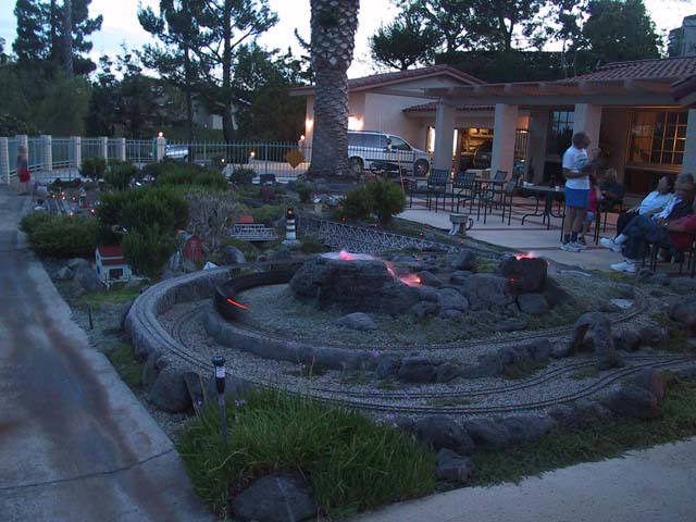
This picture shows where I had the problem by the volcano where the diverging route goes under the stone arch. Certainly doesn’t look like a problem area, but before those 6" pieces were added…
Todd, I went to George’s page on the wide radius switch, no mention of the guard rail nor picture of a shim, not to mention you as the inventor.
I don’t see evidence of you as the inventor documented anywhere, so please point it out, or rest easy on the fact that some other person in the world might have figured it out on their own.
My page references two people using brass strips, one .015 and the other using .025 … I have no pictures of the brass strip.
This is so long ago, I really don’t remember how it came about.
Greg
Jon Radder said:
My problem is picking the movable switch points in red. On a switch aligned exactly as shown above, if I approach from the left, some wheel sets will pick the upper red point and travel down the straight route while the previous car correctly took the diverging (bottom) route. This will pull both cars off the rails if you don’t run extremely slow and watch every wheel cross the point and stopping when one takes the wrong path.
Jon
I have the same problem . Especially with Accucraft wheels.
The solution is rather simple but time consuming.
What you need to do is grind the stock rail for the divergent route so that the toe of the point is back inside the top round edge of the stock rail.
I put 3 or 4 cutout disks together to make this grinding easier.
Note you also have to reshape the divergent point a little to make it smother.
For the turnouts I have done this with the point problem has gone away.
For the guard rail area, I round the tip of the frog so that the check gauge is correct using the existing guard rails.
For the turnouots I have done these mods to the derailment problem has been solved.
Hope that helps
Stan