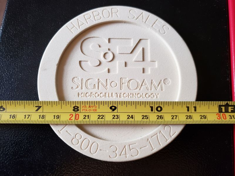
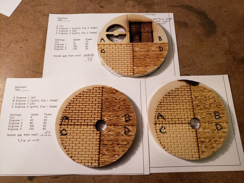
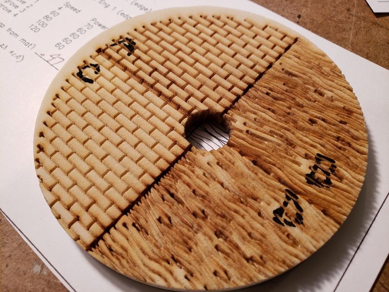
Precision Board is a very high density urethane foam material used for signage. It’s usually cut with a router, but is also touted for lasering. Basic engraved linework seems to be straightforward enough: you set the power lower and / or the speed higher to get the penetration you want. This is what I did with shingles and wood grain with acrylic, and the process seems similar with PB.
The thing I’ve been wanting to understand though is how to get different depths in the surface. I got a small sample last week for testing. Yesterday I read a little, did a simple test pattern in CAD, made a JPG of the image, and imported it to the laser software. Without much effort. this is what resulted.
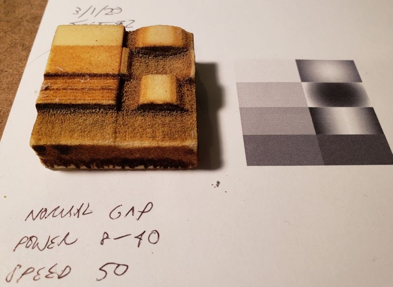
In a nutshell, the laser software I use (RDWorks) has vector and raster modes. In raster (they call it “scan”) the software interprets the image’s darkness with power level. So lighter areas are shallower. I was pretty excited to see something come out. But I also noticed that the effect isn’t linear. As you can see, the really shallow passes don’t do much. But then a certain power threshold breaks through and eats deeply. I suspect the surface of the PB is a little tougher / denser, causing this effect. No big deal though.
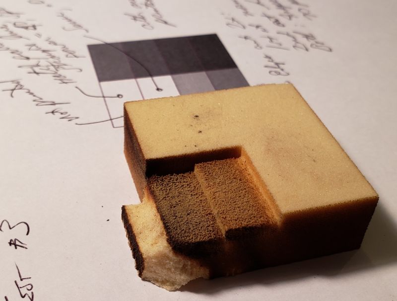
In the above test, I blended the raster jpg with a vector line drawing of the borders. That way, after the depth-cutting was done, the vector linework layer (set to high power / slow speed) kicked in, and cut the material. That took 2 passes though, because of the thickness. But this mixing & overlaying of files was difficult, even in this simple test. Complicated buildings, with cuts and deepened areas, would be a pain to register.
However, I noticed something interesting in the software settings: that you set your resolution in terms of density of laser passes. Like, if you set the density to .12mm, that’s the distance between passes. So I figured, why not make a hatch pattern in CAD that has the right line density? That way, all the graphic commands can be done in the same CAD vector file, without messing with JPG’s and all that. Here’s the first test I did like that.

The upper left two boxes were done with a simple cross-hatch in CAD: .005 & .010 spacing, set to power & speed as noted. And it came out just like the jpg (raster) areas in the other 6 boxes.
So that was exciting. I ran a few more tests, to judge the differing effects of speed, power and nozzle gap from the material surface.
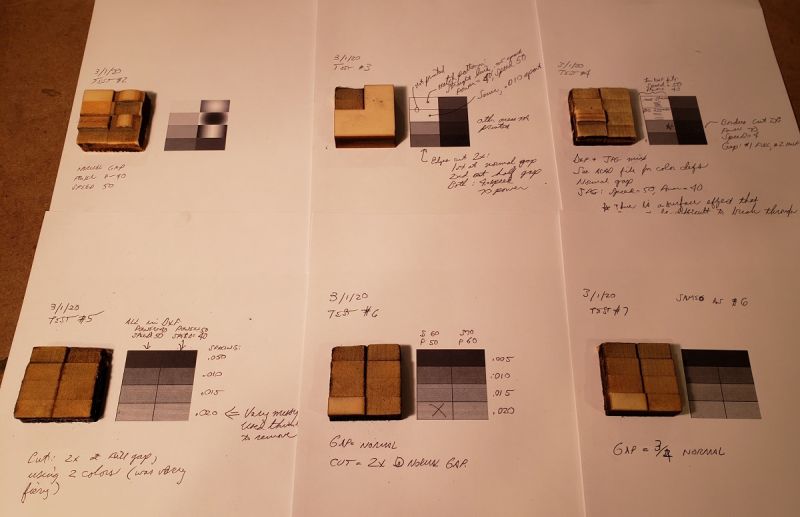
This one was all vector file (lines in CAD), comparing power / speed.
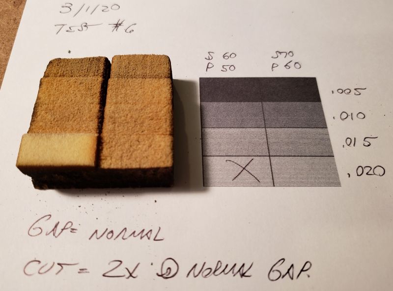
You can see the lines in the foam.
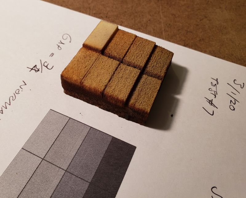
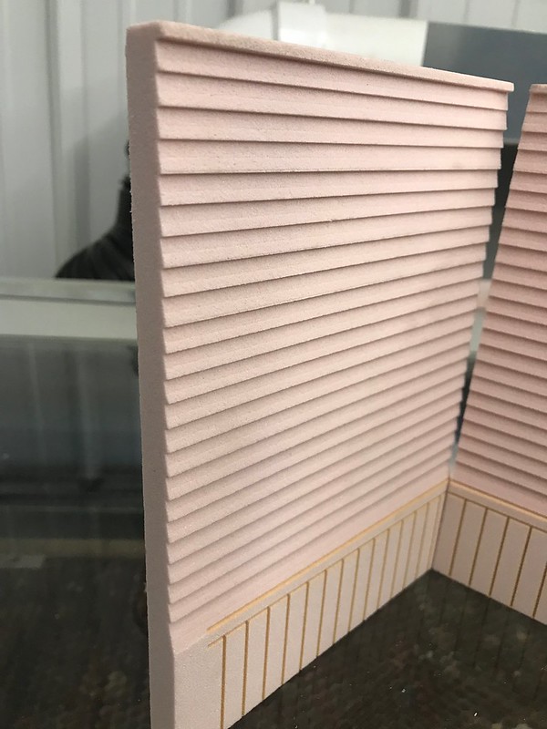
I mainly need a couple of depths, just to give some sense of texture. And from these tests, that seems quite workable. These cuts are about 3/32 and 3/16 deep.
Why is this making me hungry?
===:>Cliffy

