Jon said: “exposed”
edit because I can
Jon said: “exposed”
edit because I can
Had the mobile clearance gauge (AKA Bachmann 45 ton) out on the new track yesterday checking things before permanently attaching the track. First test: The left switch off the main. I intended this to be tight. No fingers ion the hand rails please…

It gets by without scraping. The loco is wider than my widest car, but short, so a long-car tests is also needed. I pulled these past the pinch point with no issues…
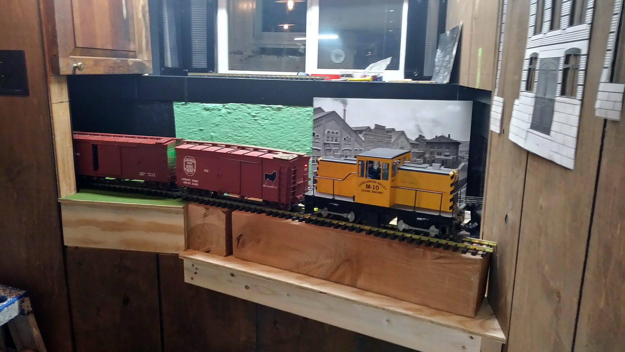
Next; check the left switch - McGillicuddy’s lead. Must have room for a 6mm mounted print on the wall without touching…

And, as expected, M10 will not fit in the uber-tight box at McGillicuddy’s - but the box car will…
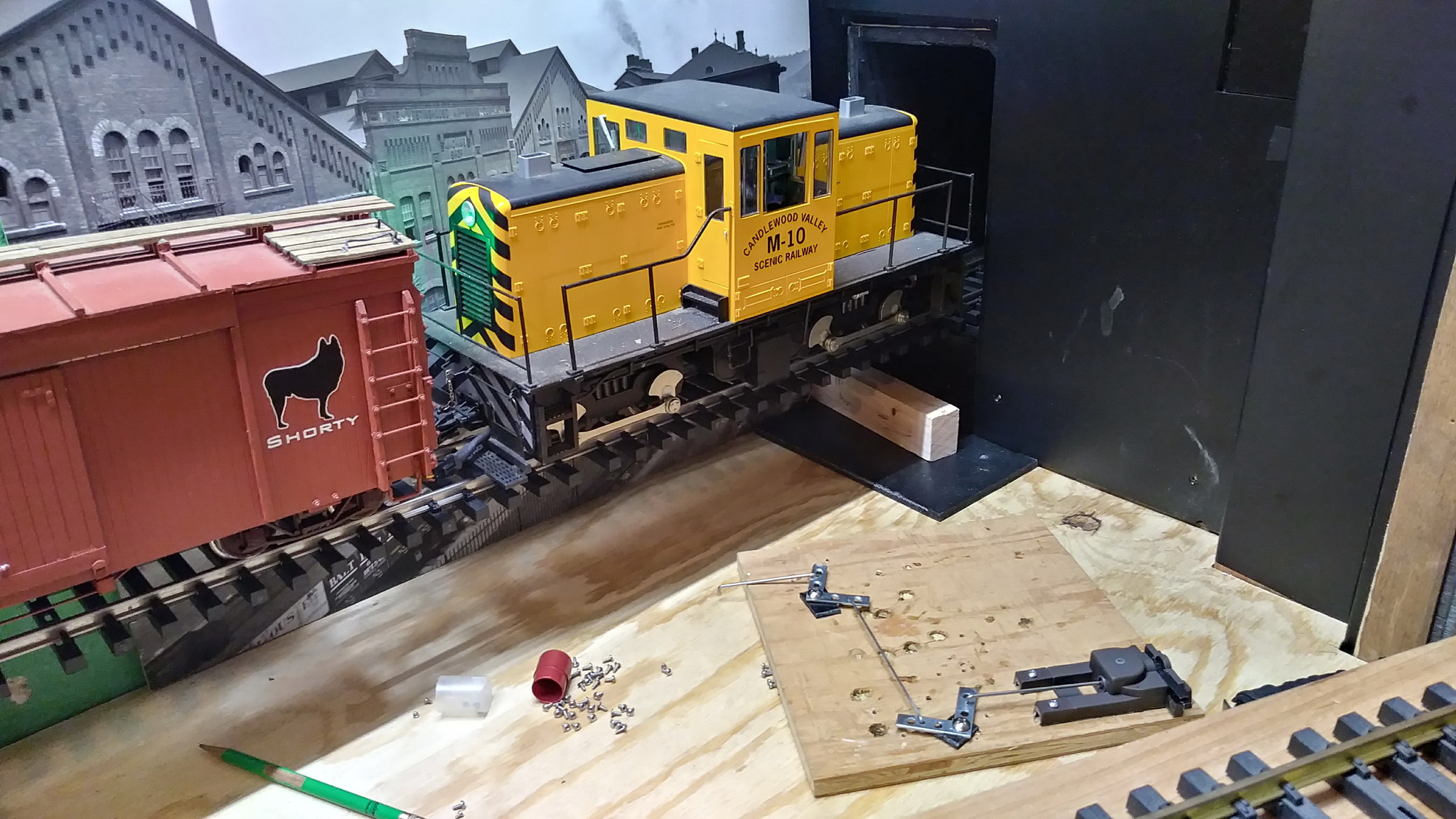
In the foreground you might notice my experiment with remote mounting a switch stand. The McGillicuddy’s switch can’t be reached from either end (without climbing in) so it will need a way to be thrown from a distance. A choke cable would work, but I think I can make something with linkage that will work as well. I am going to stop at the RC Car hobby shop tonight and buy some quality push-rods and fittings. Too much distance for extra slop. I thought for a few moments about just using a servo, but then I need electronics to drive it. A fun someday project, but I am in a hurry!
Nice progress, Jon… (http://www.largescalecentral.com/externals/tinymce/plugins/emoticons/img/smiley-cool.gif)
In typical C.V.S.Ry. Over Engineering Dept. fashion, the remote actuation of the McGillicuddy’s lead switch has taken on a life of it’s own.
Borrowing some hardware ideas from the RC Plane industry I picked up a length of Sullivan Carbon Fiber Golden Rod semi flexible control rod. First task: make a tight connection to the throw bar using a clevis provided in the kit. I reinforced the throw bar eye with a thin piece of brass that was drilled as an exact fit to the pin tin the clevis. No slop in this connection…
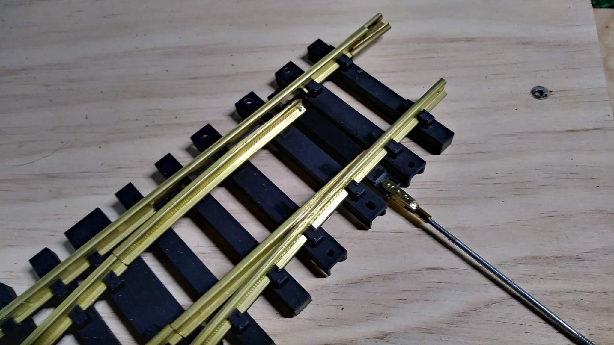

Next I worked out the route from where the stand will be to the switch. It will cross the lead through a short straight. I notched out a 6" piece of track and glued the outer tube in place. 72Hr full cure time (: 

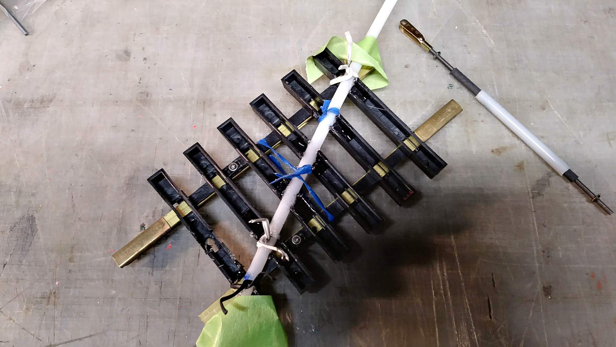
To get this done all of the track laid out and screwed down yesterday was pulled up.
Trying to come up with a cool railroady looking idea for the bell crank or two I will be using to turn the linkage at sharp angles.
If you build it strong enough, it will break something else.  Never forget to use 15 lbs. of weight, when you needed an extra ounce. This is what will make archeology so much fun 2,000 years from now. It’ll be a “hold my beer and watch this moment”. Way to go!!!
Can you put a shanty over them at their location?
Ric Golding said:
This is what will make archeology so much fun 2,000 years from now. It’ll be a “hold my beer and watch this moment”. Way to go!!!
I’ve had that exact thought; but maybe just 50 years from now. Can you imagine buying a home then when gardening find Deep Cut Tunnel buried there? What the hack would this have been??? A drain to nowhere???
Joe Zullo said:
Can you put a shanty over them at their location?
Not really enough room for much in the way of structures here. I need to look at how it was really done with the manual inter-lockings of days gone by. Probably just some simple ground mounted hardware. The tube alone will look pretty ugly. Will probably wrap it in vinyl. I think I may have some paint mask kicking around work with that rust paint on it!
I stopped at the local RC Car/Plane hobby store today and picked up a few bell cranks. Tonight I bread boarded the linkage. I used some of the extra parts that come with the Bachmann throws to support the cranks. This is close to what will be the final set up…
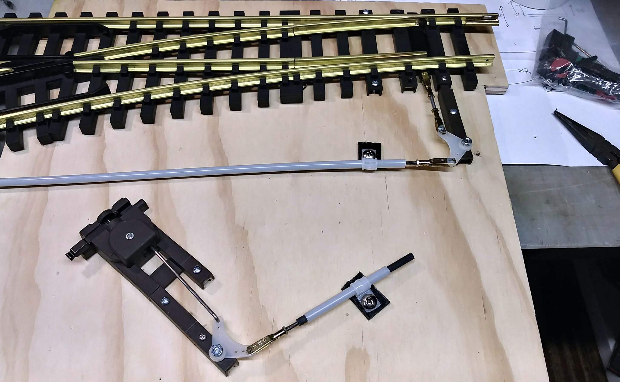

I laid out the breadboard on the new bench to measure the tube and place the throw. Before this picture was taken the rod on the throw was changed to the shorter one and the crank moved…
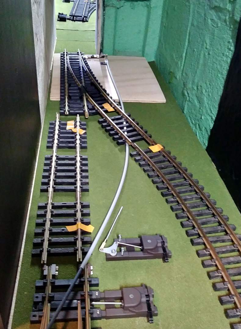
I cut the tube and attached the throw and put all the track back together and screwed it down. Tomorrow I need to crawl in again and screw down the bell crank and the tube. When that is done I can finally install and load the drawer.
Linkage was installed last night. Reaching through the tunnel to screw things down was a bunch of fun. It is now functional and clearance tests have been run making sure the throws (without the indicator) do not interfere with my mobile clearance gauge. It works great to open the switch (pull on the long rod) but isn’t perfect pushing. I traced that problem to the throw itself. I might be able to tweak the gear positions to resolve it, but for now a quick push on the bell crank gets it done.
Latest pic…
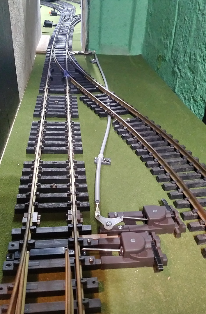
With this done, I can finally put the drawer back on the track and start loading it up. This project is two days away from 2 months in. I would like to be able to get rid of the temporary shelving holding all the stuff removed from this spot to allow construction to happen. Hopefully this weekend I can wrap up construction details and clean!

Is it possible to flip the rod coming from the throw … so it is mounted under the cam ? It might be binding.
I will have to open up a spare and look to see if there is enough room inside the housing for the rod to bend up, rather than down. Not sure if that would help as it dos not seem to be binding at all. I could also flip over the bell crank making it closer to the tie which would straighten the rod a little. It is a major pain to open that little clevis to disconnect the rod. If I am going that far I might try adjusting the length to get the trow more even from position A to position B.
All of this is low priority now since it really is no big deal to give it a nudge after it’s flipped.
Jon,
from an engineering perspective are you bell cranks moving thru equal angles relative to the center of the points? this may account for an error in the amount of throw translated between locations.
Al P.
Al Pomeroy said:
Jon,
from an engineering perspective are you bell cranks moving thru equal angles relative to the center of the points? this may account for an error in the amount of throw translated between locations.
Al P.
I wish I was smart enough to answer this question (https://www.largescalecentral.com/externals/tinymce/plugins/emoticons/img/smiley-surprised.gif)So, I’ll do what I usually do in such cases; guess. I didn’t make any measurements and when it came time to screw the switch to the bench I wasn’t able to see very well and what I could see was from an off angle. Both bell cranks are mounted on a beam that is roughly 90 degrees to the track, but likely out of square by several degrees. The throw rod and the push rod to the points is also at roughly 90 degrees to the track. The carbon fiber rod curves a bit, but is generally parallel to the track. Does that give you any hint?
If I disconnect the rod from the throw, I can manually move the points cleanly to both extremes using the bell crank at the throw.
One simple stupid note that you will understand. Perhaps your conduit is pushing upward when closing because you don’t have it strapped down at the end. I personally would move the conduit clamp closer to the end before I play with tweaking it. The solid rod on the bell crank also looks like it’s a bit tight in the hole (…) maybe drill out that hole a bit for some slop. I played around a little with bell cranks in the past and they can be a bit tricky…(https://www.largescalecentral.com/externals/tinymce/plugins/emoticons/img/smiley-wink.gif)
Honestly I don’t even know which end you are controlling it from beer 4!
I’ve moved on to getting the basement put back together. The switch tweaking can be done later. I did add another clamp Roo, but on close analysis the problem is the bell crank mount at the throw. It is not rigid.
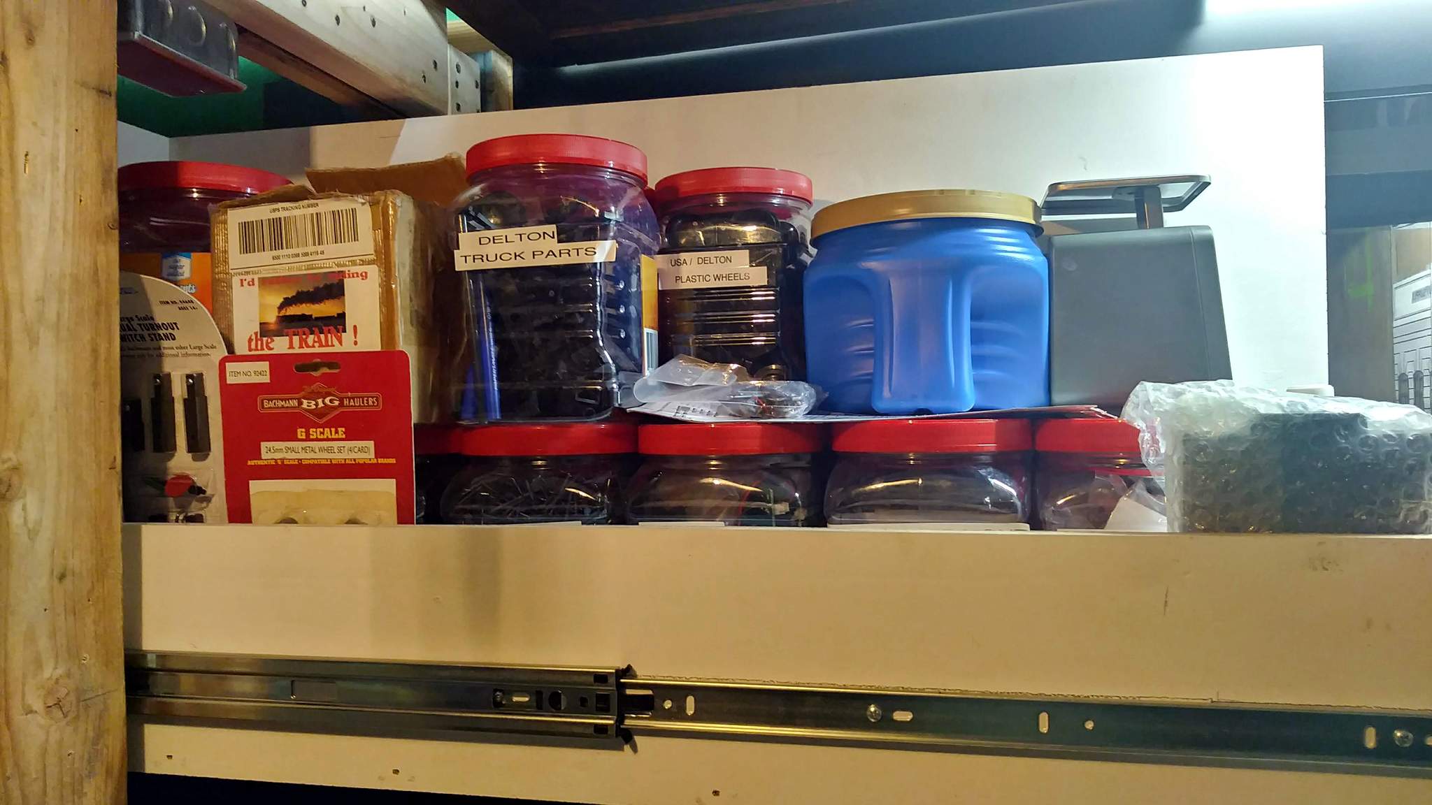
I added an end to the drawer with 10mm coroplast, then put it back in place and got it loaded up with my grapefruit container storage system! Here are the latest pics…
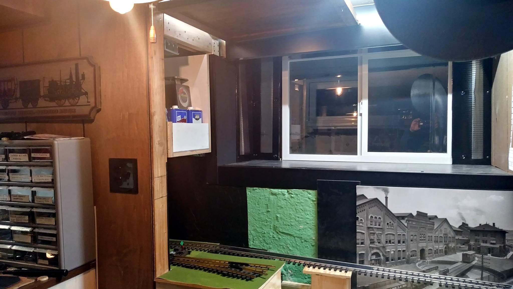

Today’s project is to install the film on the left pane of the window so I can start loading junk up into the “shadow box” area.
Jon, not sure if you looked at these pictures very closely, but there is some dude taking pictures through the window (https://www.largescalecentral.com/externals/tinymce/plugins/emoticons/img/smiley-surprised.gif)I like your storage solution. Good use of available space.
Dan not to worry you only see his head … must be a short guy… (https://www.largescalecentral.com/externals/tinymce/plugins/emoticons/img/smiley-wink.gif)
Pay no attention to the man in the window! Yesterday’s goal was achieved. The large plastic shelving unit that I set up to hold all the stuff removed from this area for demo was emptied out and a home found for everything. Outdoor buildings inside for winter went up in the ‘Shadow Box’. A bunch more stuff got loaded in and on the antique book case. The white plastic shelf unit that used to live here was eliminated and both shelving units were hauled up to the attic until they are needed again. The latest long shot shows the progress…
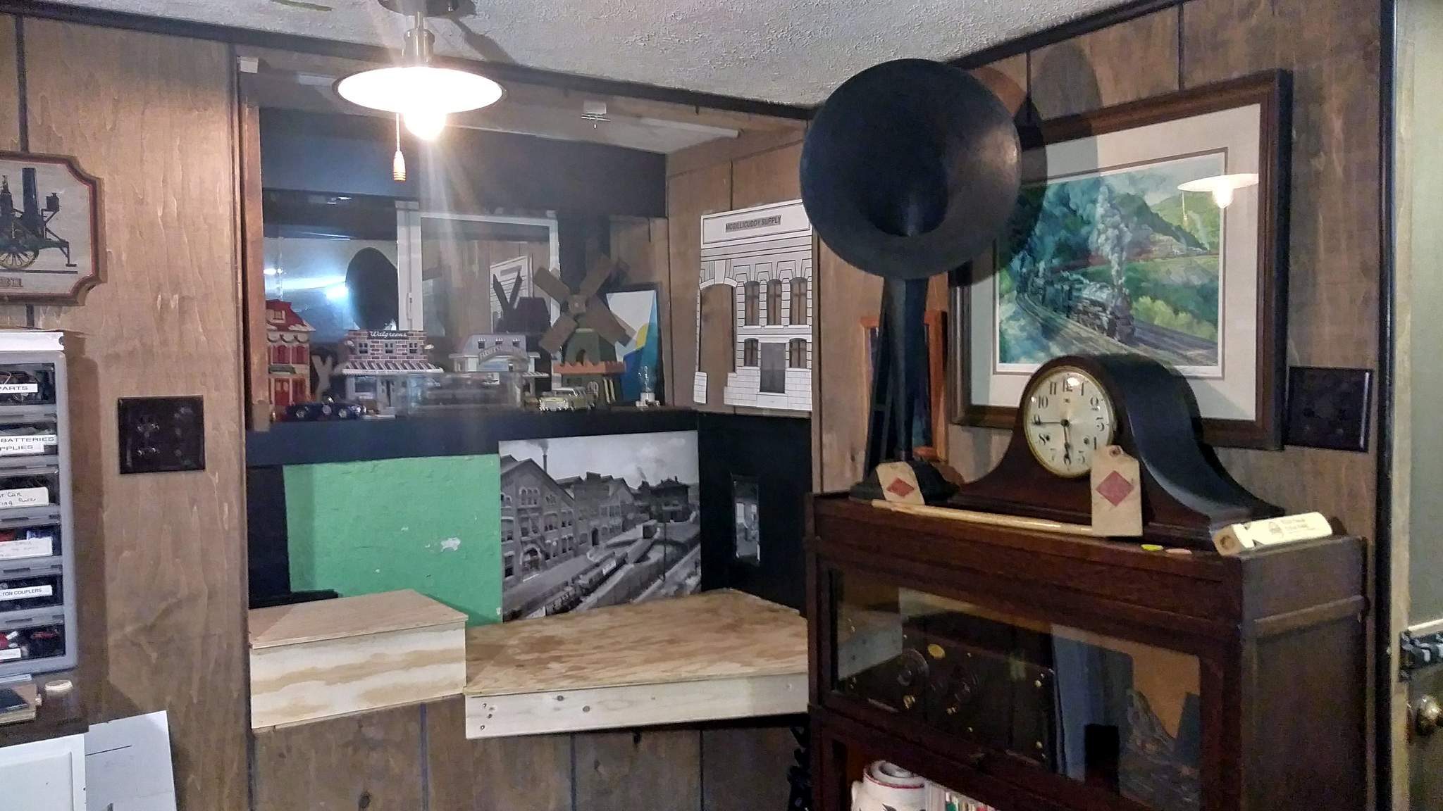
Construction is now complete, except for a little more fake grass and some aluminum trim to dress things up.
With clean-up done I turned my attention back to that pesky switch mechanism. I think Al correctly diagnosed the problem even though I didn’t know how to measure the angles; when I looked at the two cranks as a matched pair, I noticed the difference. The angle error was compounded by a weak mount for the closest crank causing it to lift (as Roo noticed). The solution was to improve the pivot mount so it can’t flex and move it to the other arm correcting the rod angles…
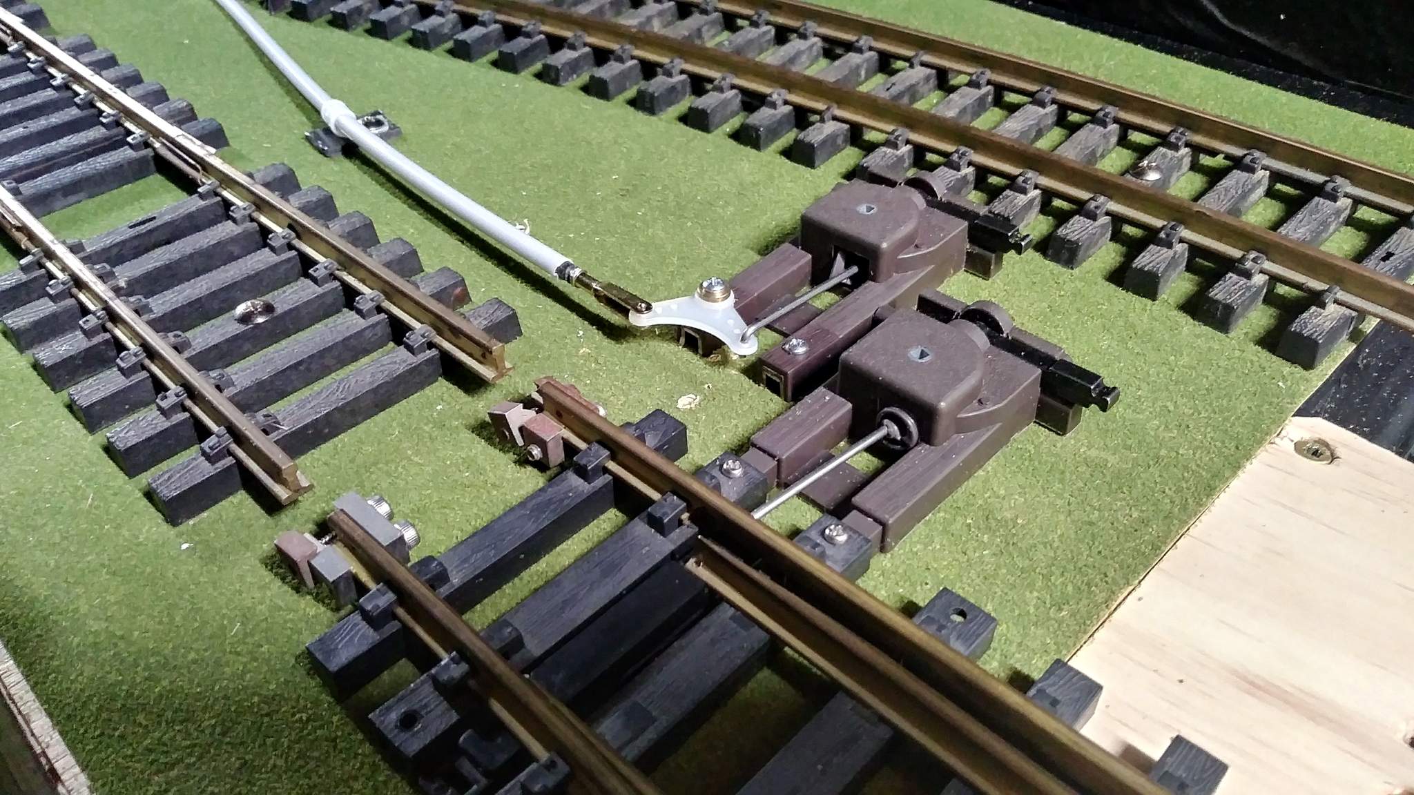
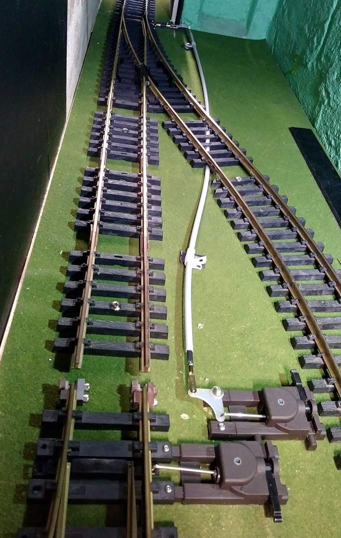
With these changes the throw gets mounted about .75" closer to the camera which now interferes with the throw from the right switch. I can either go through hell to shorten the rod and cover (everything apart again) or add a short section of rail to move the switch. Being lazy I’m going with the second option.
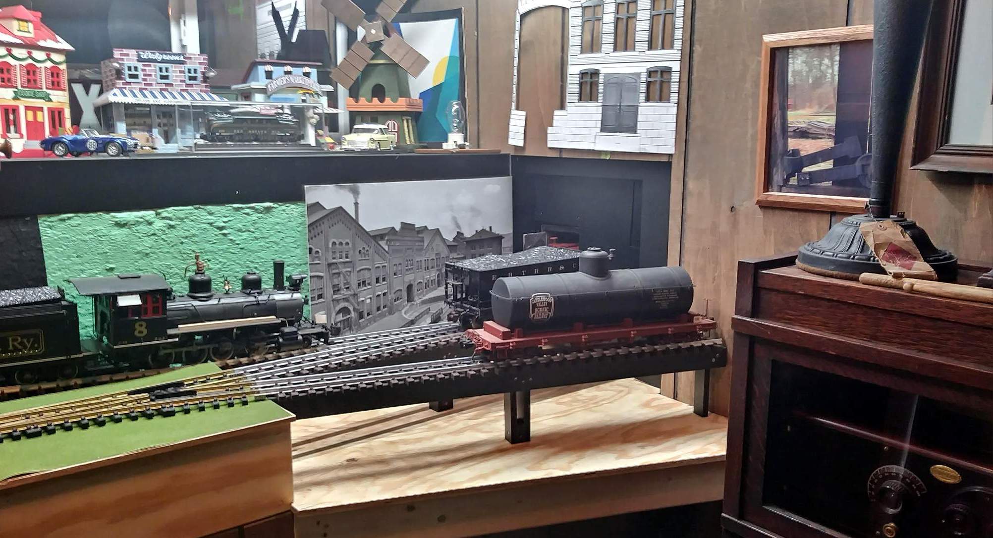
Today was track and roadbed day. Eventually I will build wood trestles, but for now, black PVC roadbed stands in for the trestles. I cut track to fit from 7 foot code 332 aluminum track by Accuctraft. The aluminum track is super easy to cut on the chop saw with just a little clean up with a file or sanding disk. Final track alignment…
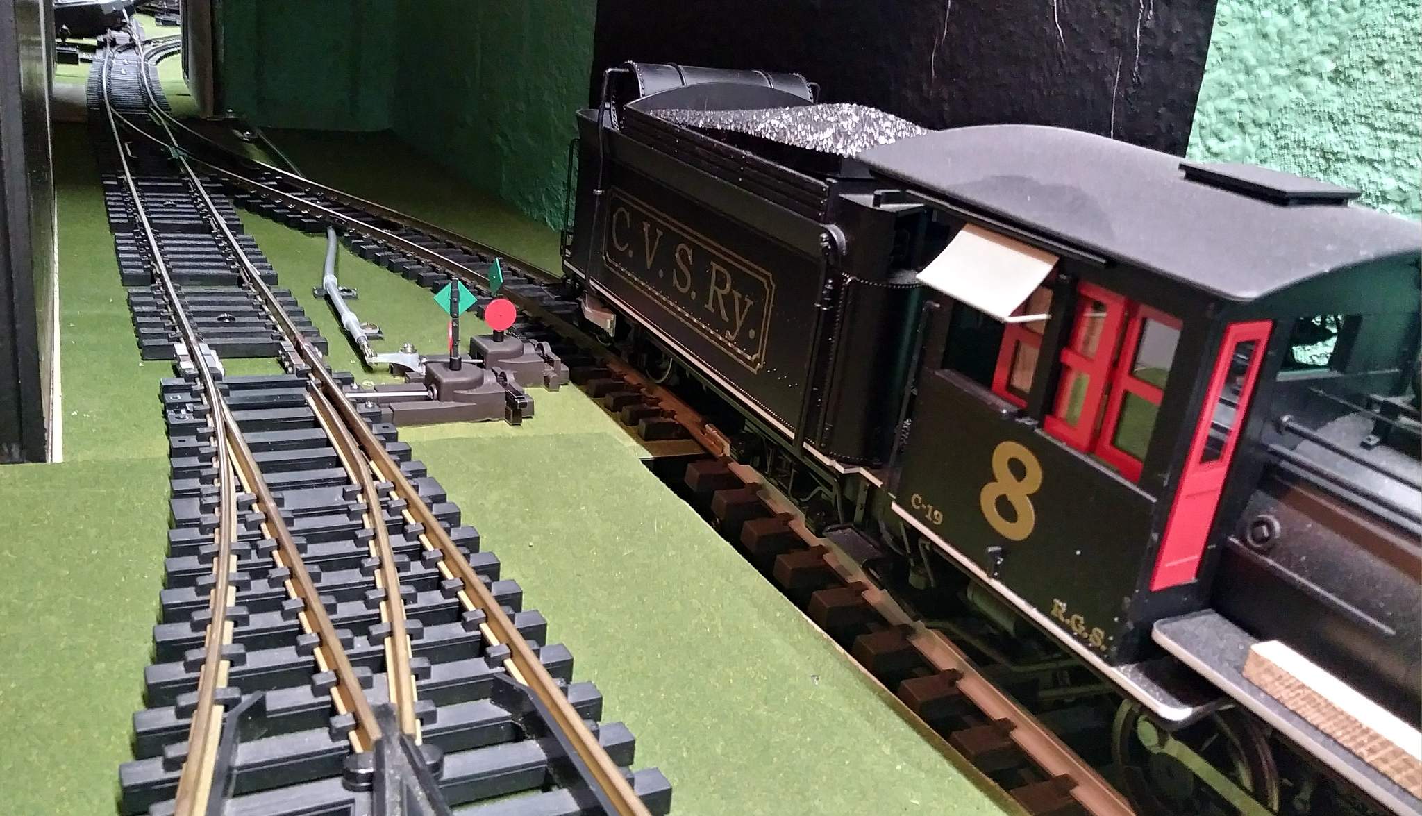
Final switch machine positions…
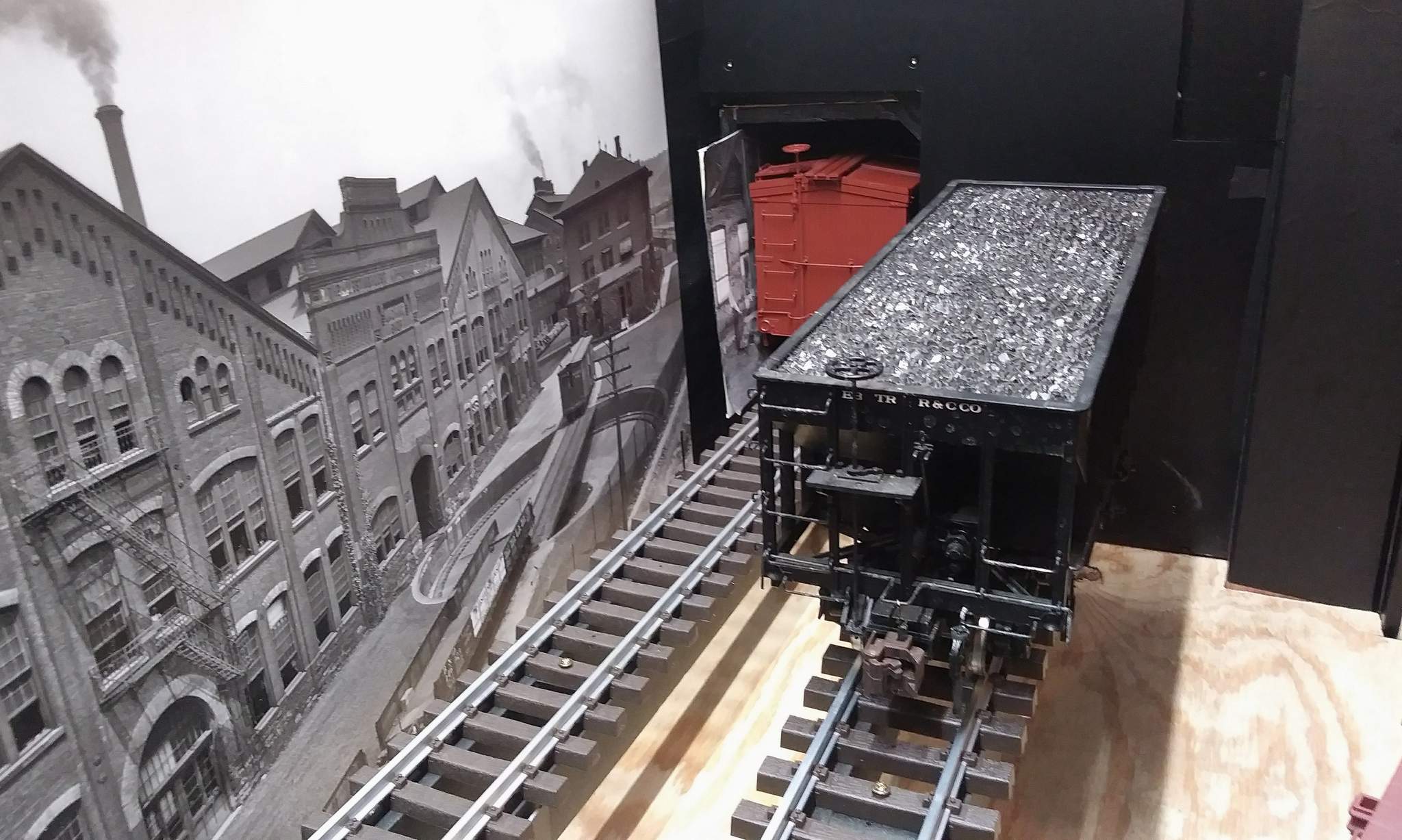
The final grade measurement on this short 4 ft section of track is 4%. The box car still fits…
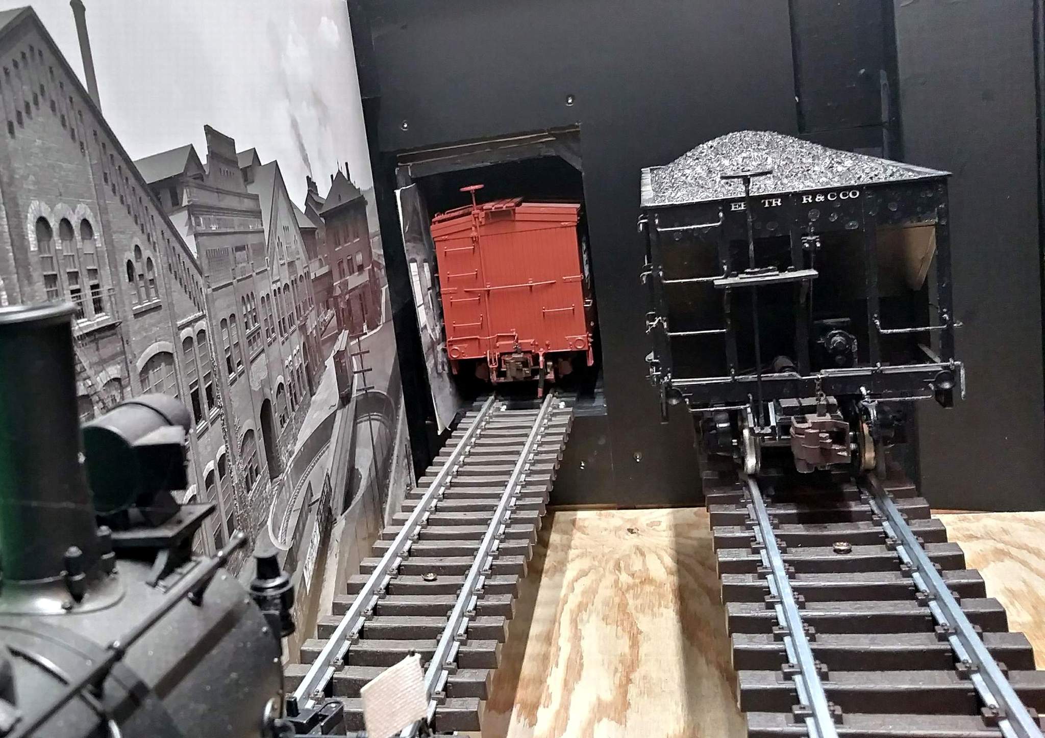
All of this is just one step above dry-fit. screws are in, but it will all come apart. I want to yank it up now and put down the grass mat and finish the edge trim. I also need to cover that last bit of green concrete block. I can’t wait to get back to work on McGillicuddy’s to finish this scene…
