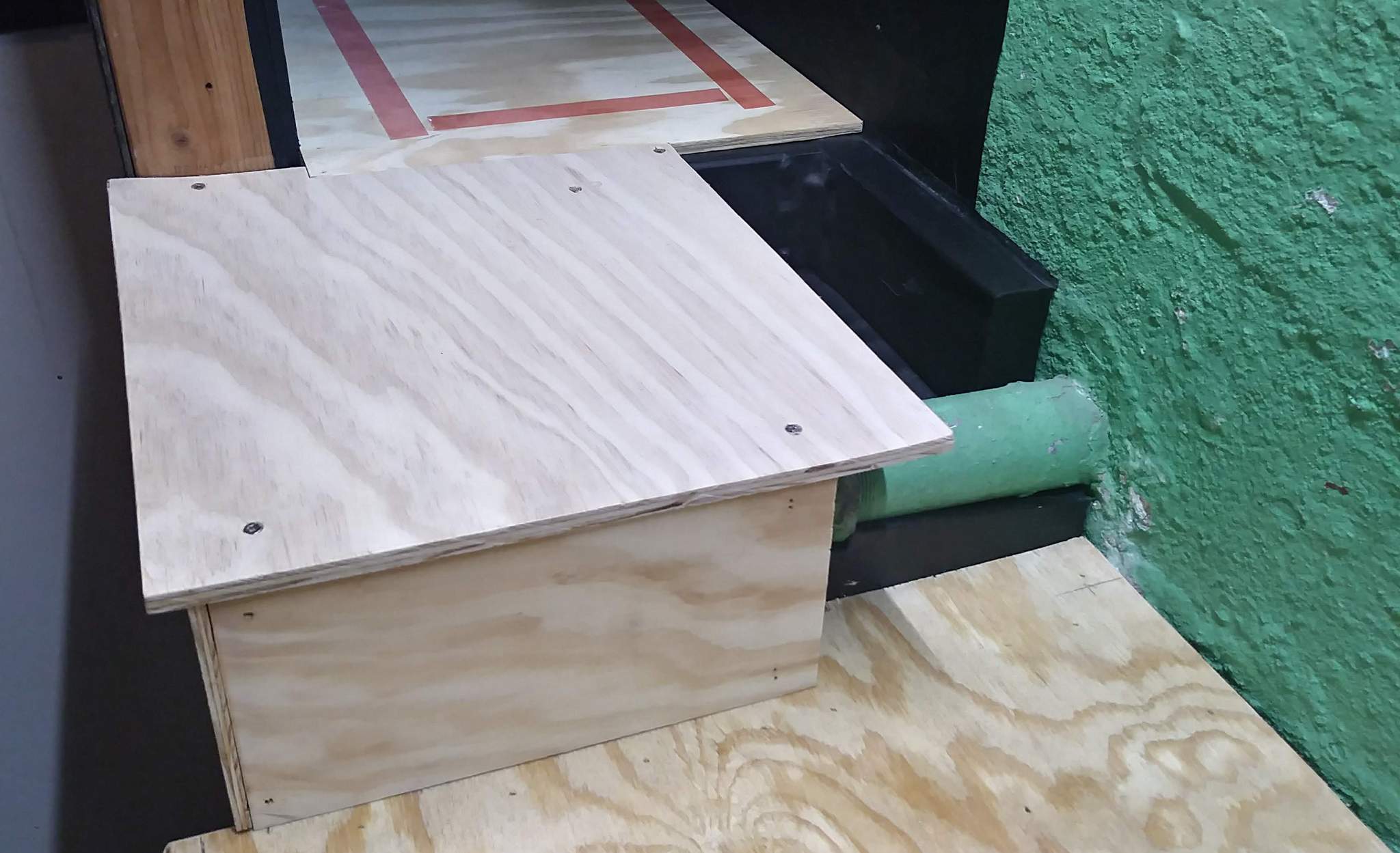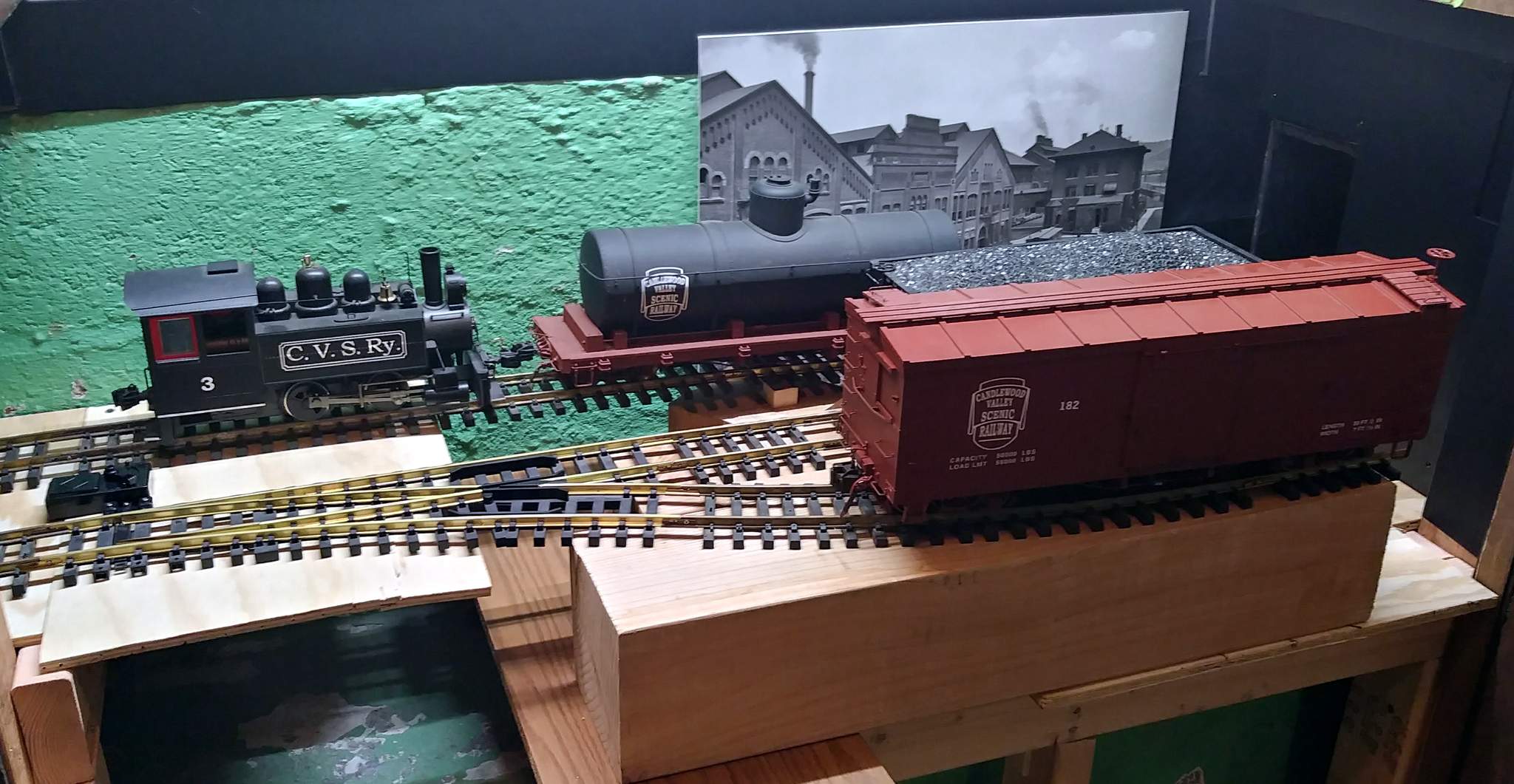
What if you had a curve going towards the right after the switch in this pic it goes to the left …

What if you had a curve going towards the right after the switch in this pic it goes to the left …
That’s the part I like, moving track around, finding out what fits and what don’t, what works and what don’t.
Ken Brunt said:
That’s the part I like, moving track around, finding out what fits and what don’t, what works and what don’t.
And thinking it works…until you run a train…(https://www.largescalecentral.com/externals/tinymce/plugins/emoticons/img/smiley-foot-in-mouth.gif)
Bruce D. Chandler said:
Ken Brunt said:
That’s the part I like, moving track around, finding out what fits and what don’t, what works and what don’t.
And thinking it works…until you run a train…(https://www.largescalecentral.com/externals/tinymce/plugins/emoticons/img/smiley-foot-in-mouth.gif)
Exactly. That why this was a connected rail test. Those cars came in by loco from the working layout. I spent some time switching out both configurations to see what worked.
@Sean - A curve toward the camera was the original idea. I decided that the one extra car it would gain was not needed. I’d rather be able to put back the antique glass front bookcase with the clock on top in teh spot it came from. After all, it’s not how many cars you can put at a spot, it’s how many spots there are for cars. Get it??? Just as much fun to switch out one as three.
When I start cutting track, both tracks out of the switch will be dead straight about 36" long.
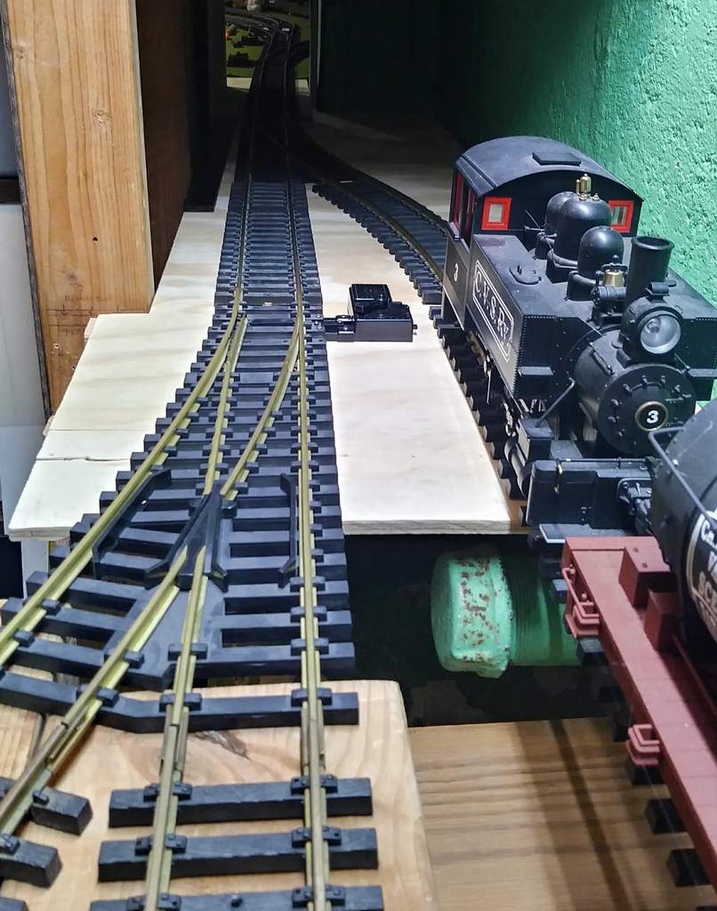
In this pic , could you move the switch back a tad, so you are closer to the stud … how close is the box car now or are you just right ?
Going back to the block wall idea for the fascia … after seeing the latest track plan …
Fancier
Sean McGillicuddy said:
In this pic , could you move the switch back a tad, so you are closer to the stud … how close is the box car now or are you just right ?
Again - this is not final alignment. I used sectional pieces that I had on hand to get close. Once the construction is done I will move things as close as possible while will maintaining full Fn3 clearances. That places the switch back about 8 ties from here it is in this pic.
And yes, a retaining wall is still in the plan. Eventually all of the track crossing over the low section will be on wood trestles. I’m thinking possible a coal unloading trestle and maybe a conveyor system feeding the building.
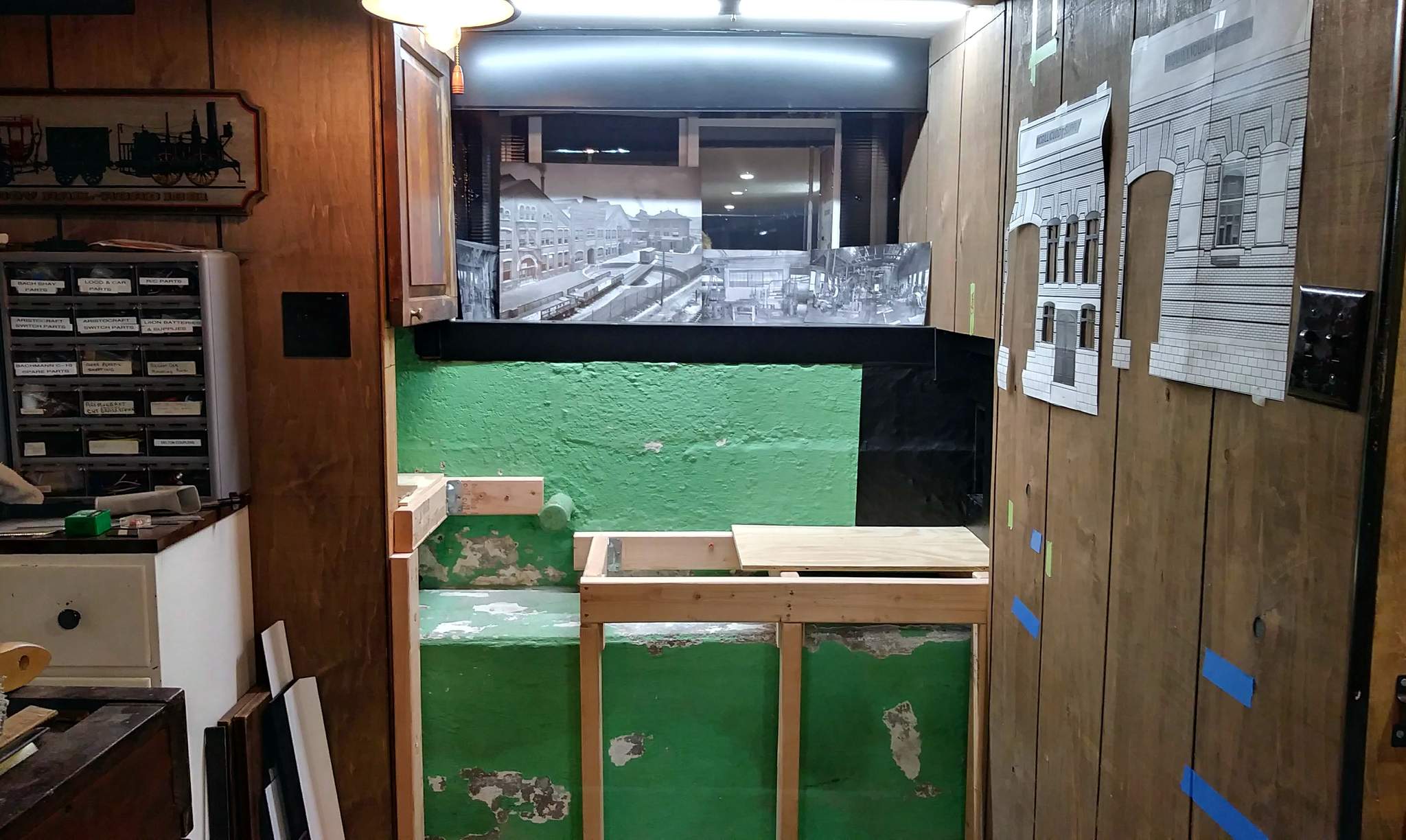
New pic required !
Nothing has changed from that angle, but behind the wall the abyss has been sealed up & preparation made to hang sliders for the shelf / drawer. I can’t finish the exposed bench untill all work is done back here. I need that exposed concrete to step on. Today’s work…
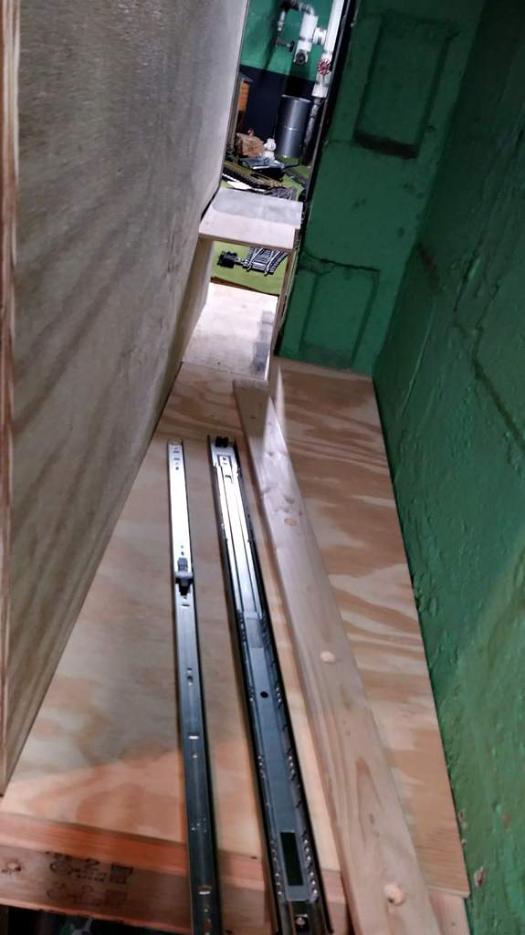
Great pictures! Having been there, I can fully understand the space and what you are doing. Great use of space!
I took a snow day today, so a lot got done. First up: Mount a 1x3 to the block wall with Tapcon screws as a mount point for the drawer slide, Do similar with a strip of 1/4" plywood on the wood wall side then mount up the slides. Getting everything square, level and parallel was a bit of fun. With that done I was ready to close up the bench frame - all except one member which needs position calculation using track in final configuration.
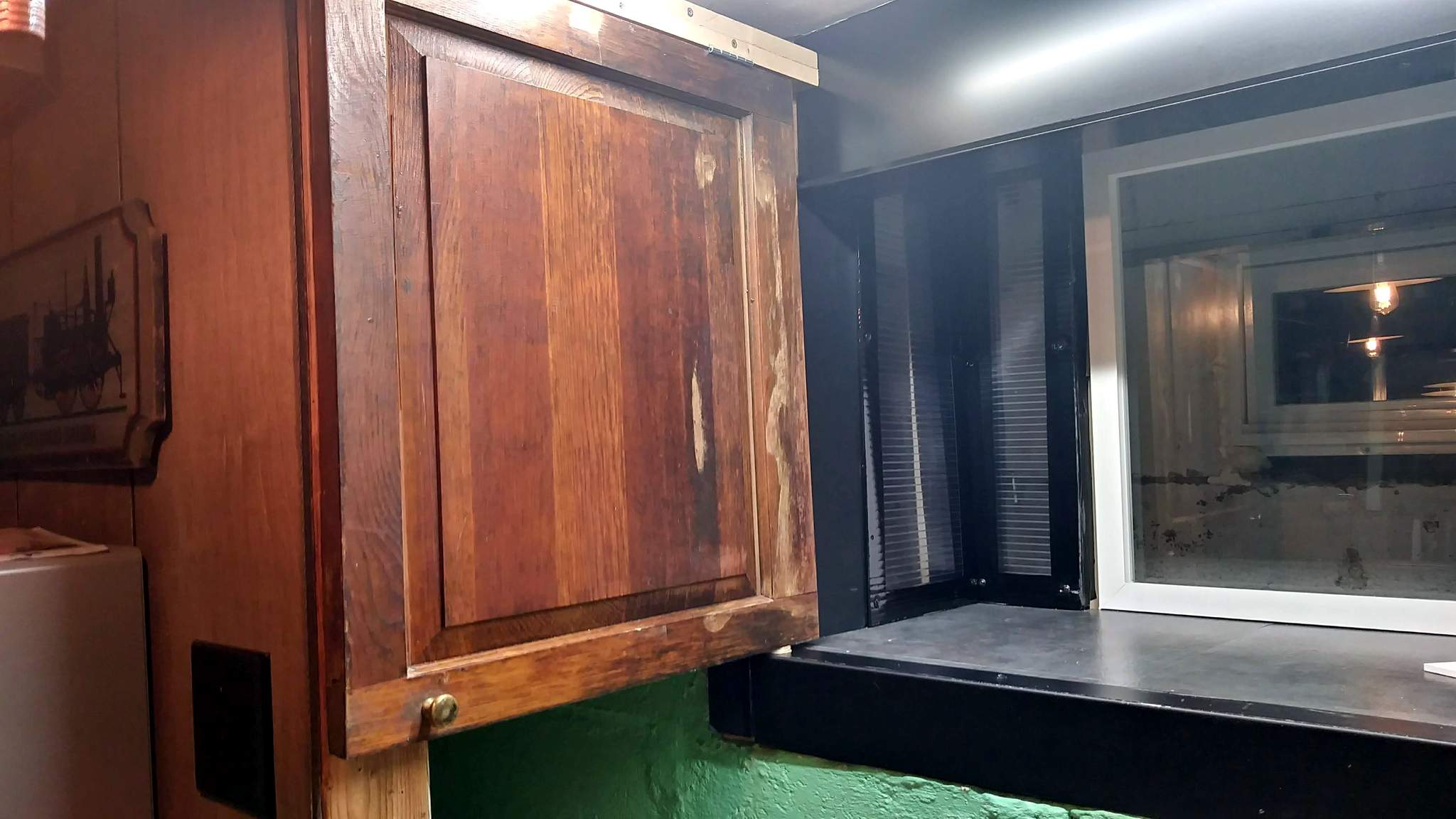
Here is the face view - I’m trying to keep the angle close to the same so Sean can animate them when it’s done! Door closed; shelf stowed…

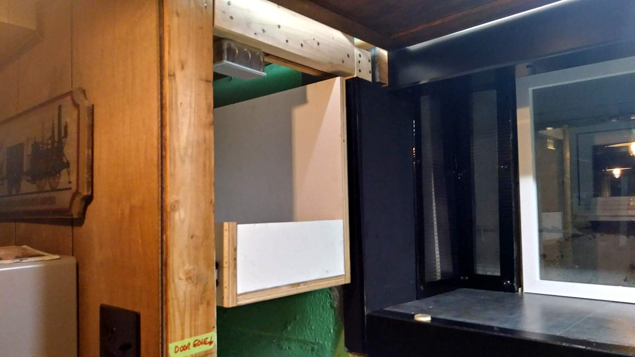
Open the door and slide out the test shelf frame…
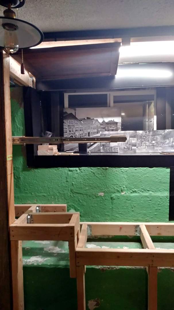
Looking in, toward BOX Tunnel…
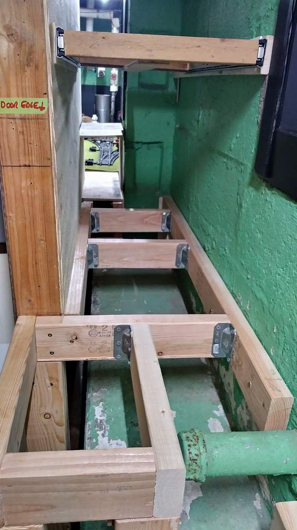
Just above the pipe in the last pic will be another cross member closing the box. This will be the transition point for the grade so it needs to be at a track joint. I just hope it’s not too sharp causing coupler issues.
Before the next steps I need to be close to final track alignment, so set it all up again. I can get adequate clearance on the box car and still get 36" or better of track after the switch on both legs. Checking where the angle ends up I can still fit the bookcase on the wall…
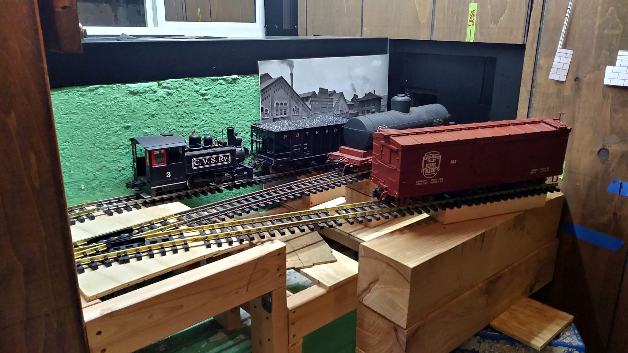
Next I need to frame out the face angle. Then I can cut deck plywood. This weekend I might get paneling cut and put back on.
BTW - There is some serious lens distortion in the portrait shots. It’s a lot closer to square than it looks!
Very clever drawer! (https://largescalecentral.com/externals/tinymce/plugins/emoticons/img/smiley-laughing.gif)

Hmm you hinged it from the top …I would of just mounted it to the race of the draw slide …would help to keep thing on the shelf…
Jon
How are you opening up that door … with a pole … I can’t see you standing on the floor doing that … Then you will have items infront of that area!

Paneling … I would install it on the lower section ( that you see on the right ) and maintain that level all the way across …

The short section that is left , I would go with the retaining wall idea , … so you need a piece of blocking to carry the levelness of the lower section … am I making sense ?
@Sean - I was going to do a quick reply saying that’s NOT the plan, but you got me thinking - and I like it!!! I had already planned on retaining wall as the finish on the drop face from high to low, but was just going to use my RR Standard black trim at the deck edge. BUT, now that you mention it, that paneling would be hard to keep out of photos of the trestles I hope to build on the low section so it makes sense. And it’s easy too.
My only issue now if depth. The thinnest foam I use is 3/4" which will sit proud of the paneling by a 1/2". Maybe a Z bend of my black aluminum fascia trim wiuld both finish it and support it.
Today at work I had some time to cut a drawer kit from an old 3/4" plywood sign. Nice part is it’s pre-painted except for the cut edges. I hope to get that assembled and installed tonight.
Rumaging through the junk pile at work I found the good parts I salvaged of an old rotting MDO Plywood sign. I had cut them off and stashed away months ago with no use in mind. Today it jumped out as perfect size to cut a drawer kit on the panel saw. The “kit” came home with me flat and was assembled this evening using Fuze-it and finish nails. It turned out about 3/16" wider than the test drawer and I was worried it wouldn’t fit. Surprise it did!! I guess I’m a cabinet maker now.
@Sean - The door opens up because initially there was to be a static shelf above the RR. The sliding drawer idea developed after the door was installed. The ceiling is under 7 feet so I can easily open and latch the door when needed. Doing it this way keeps the weight off the track too. This MDO monster is heavy and the entire package - drawer plus load is only rated to 100 pounds.
So here it is…
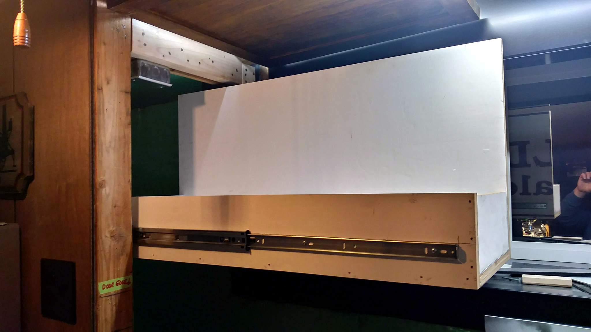
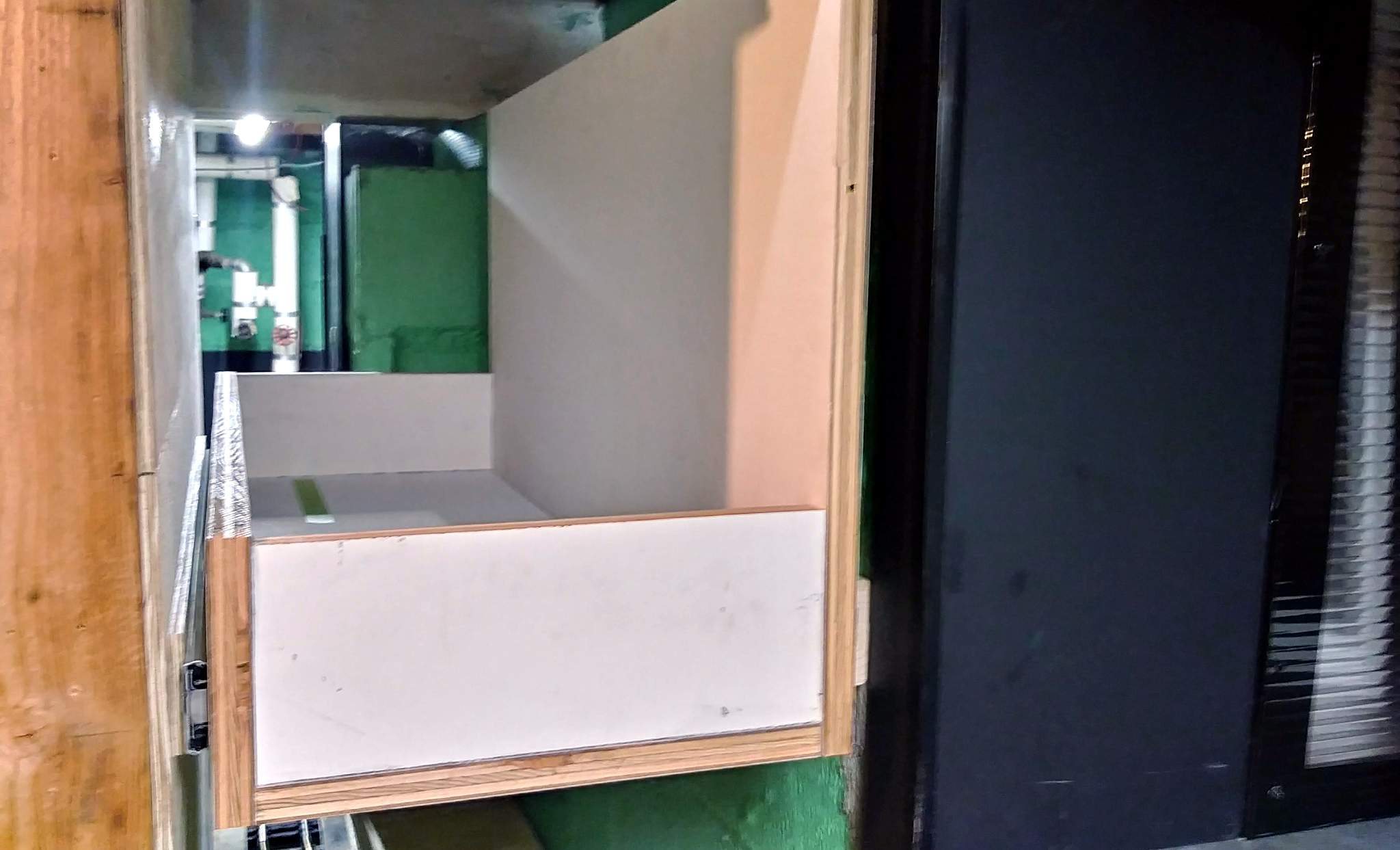
I think I will hang a lightweight shelf about half-way up the back and close in the end with some PVC just to keep stuff from dumping out. Almost ready to start putting stuff back (https://www.largescalecentral.com/externals/tinymce/plugins/emoticons/img/smiley-smile.gif)
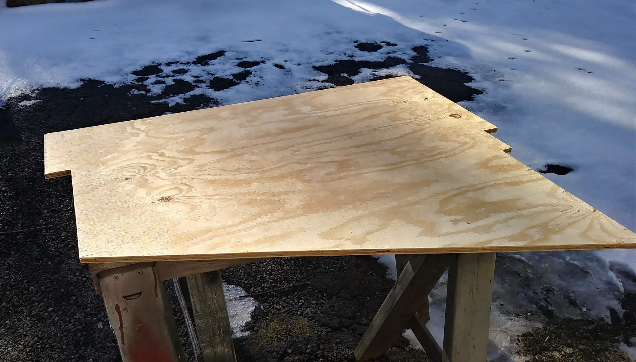
I put in close to a full day on this today and got the framing closed in and decks in place. The biggest challenge was the low deck. I wanted to make it in one piece and used a heavier plywood (15/32). It was a complicated cut. I took my time and verified all the contours. It ended up being a perfect snug fit…
Here is the obligatory long shot. I might get the furniture put back tomorrow…
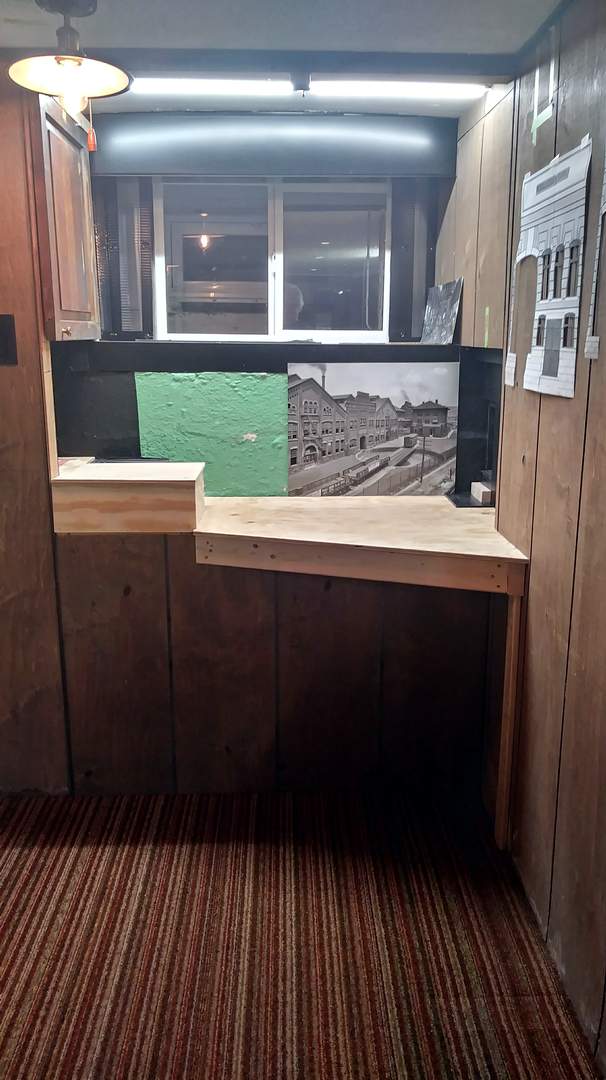
Gotta cover the last of that green soon!!!
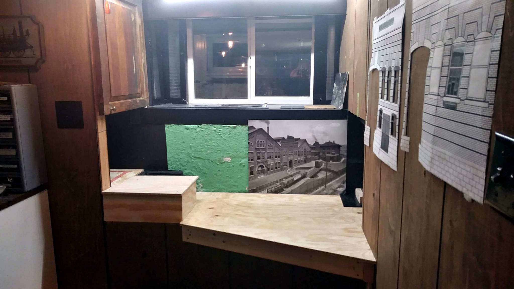
The next project is to get grass down and track laid behind the wall so I can put the drawer back in and start using it to clean up the mess I made readying this spot for demo on Christmas eve.
Looking great there Jon !

Am i right in thinking that you are going to place the stone wall on the exposed 2X lumber, it looks like you did think ahead and have enough plywood overhang…
Close, but no cigar! The exposed 2x4 will be trimmed out same as the rest of the layout: Covered with .063 flat black aluminum bent under at the bottom. The aluminum will continue at the same height completely across the opening. The vertical plywood skin is a temporary cover to be replaced by a carved foam wall at some point. I may even take your suggestion and extend the pipe to come through the wall. I did leave it exposed where the track will go over it near the wall…
