Randy, nice template… 
Thanks Andy, trying not to be a slacker !
Ken Brunt said:
Some look gray, some dark brown, some look black.
Yup I agree, but I don’t think you can go by the ties around Rockhill since a lot have been replaced with creosoted ties since it started back up for the tourist age in the 60’s. The ties in that Robertsdale shot I posted on page 1 look pretty black maybe a bit brown, that would have been the 50’s I’d think this would be close, unless some of these were replaced by then with creosote?
Perfection is often the cause of insanity. (http://largescalecentral.com/externals/tinymce/plugins/emoticons/img/smiley-surprised.gif)Just adopt Allen McClellend’s “good enough,” philosophy of model railroading, and color them “dark.”. (http://largescalecentral.com/externals/tinymce/plugins/emoticons/img/smiley-laughing.gif)
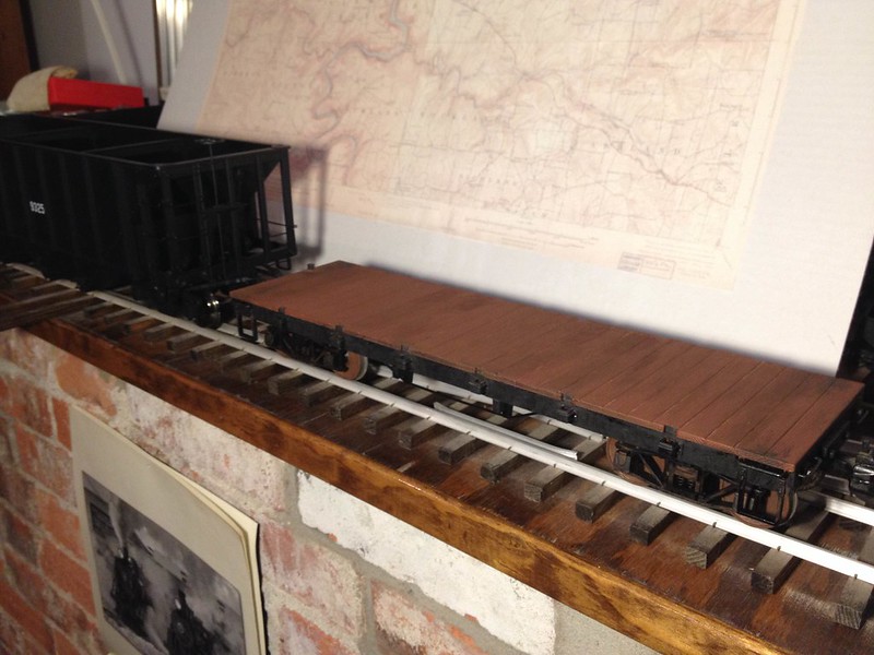
Got some good advice from an expert and I’ve settled on a color. As I’ve stated the EBT didn’t use treated ties. So they were faded gray. Ballast was a mixture of boney and cinder below and generally crushed furnace slag around the ties. Spent a little time tonight and sprayed the assembly and some rail. I’m pretty happy with it. Lighting is kind of bad in this shot.
Randy,
Are you sure that you really need the stiffener under the track? My #9 turnout is quite stiff once everything is spiked with 4 spikes per tie, per rail. My only advice would be to check and double check the gauge, especially around the frog and the points. If you have a properly set wheel set as well, it helps to make sure everything flows smoothly. When you get to laying the frog, your wheel set should be able to roll through the frog without any guardrails if you keep the tolerances tight. The other thing to keep in mind, is you might want to put a slight kink in the stock rail leading to the diverging route.
Here’s my #9 turnout before I had the points finished.

Here you can see the slight kink.

Here’s the track gauges I use. The plastic ones on the left are from Switchcrafters, the metal ones on the right are from Rodney Edgeington. The 2 bottom gauges are used to hold the frog in gauge. I have 4 each of those and 8 each of the others. Notice the one side that slips over the track is missing so it will fit over the frog.

Here’s the whole array of tools I use.

The truck helps me find any trouble spots.
Here is the only Large scale switch I’ve built so far. Lots in HO. It had/has no stretcher, but also only has one spike per side on the ties. It is a bit too flexible for my liking. I think the Key is 4 spikes per rail crossing. Then it would be rigid. For this project the stretchers have to stay for the stub switches, since all rails are cut at the same tie. So I’m keeping them on everything. I like how strong it feels already. Since I’m trying to go for a 20+ year switch I think strength overkill is best.
Craig, By the way, that switch looks great. I’ve watched a few of you switch builds.
(Edit: I did the kink thing too, along with not removing the inner foot from the stock rails. Just shape the points correctly)
Ken, Thanks for the gizmos tour. I need to make or get a few. I have a neat one in mind that I want my buddy to 3D print.
(Edit: ken I see the spiker works so well you don’t even have a pair of pliers shown. Cool, a test is underway …)
Bruce Chandler said:
BTW, here’s a shot of my trestle as I redid the spikes a few years ago.
In the foreground you have the spikes put in with the spiker. 3/8" spikes, 2 per each side of the rail. The rest of the trestle shows my 1/2" spikes rising up in revolt. At one time they were flush with the rail, but winter drives them out. Not so bad with the 3/8" spikes.
I thought of this photo when I was waiting for daughter at the MBTA Commuter rail station in Ballardvale, Andover, Mass. Even the real thing has that problem:

You have to be aware that on the real railroad, the spikes are only meant to hold the rail in gauge. Their purpose is NOT to hold the rail down. So; even though a spike has worked its way out a bit; it still functions as it should, keeping the rail in gauge.
Ha Fred I did not know that.
Hooray! Got the frog points yesterday afternoon. So now I present my version of a #7 turnout with only guardrails to add. I think I can bang these out pretty quick.
Nice! How does the point attach?
Randy Lehrian Jr. said:
I think I can bang these out pretty quick.
Good! You can make some for me too. After about an hour working on one my brain goes numb and I have to find something else to do. Usually takes me 2-3 days to build one.
I’m curious about that throw bar too.
Looks good, Randy!
Thanks John, I drilled and taped a #2-25 hole in the frog point. I get the point in place and the rails down behind it, which holds it pretty well on its own. Next I match drill a hole down through the tie. To firm it all up I put the screw up through the tie into the frog point. I actually have to pick up some #2 screws at lunch today. So even though the holes are there, there is no screw in this on right now.
My next step is to cut all of the ties for all 18 of the turnouts and get them all pre-drilled for attachment to the Aluminum bar. Then I’ll probably just build the remaining 5 blanks I need to open the main and start laying rail on them.
Ken Brunt said:
Randy Lehrian Jr. said:
I think I can bang these out pretty quick.
Good! You can make some for me too. After about an hour working on one my brain goes numb and I have to find something else to do. Usually takes me 2-3 days to build one.
I’m curious about that throw bar too.
Looks good, Randy!
My hands go numb after a couple hours. (http://largescalecentral.com/externals/tinymce/plugins/emoticons/img/smiley-foot-in-mouth.gif)I think I probably have about 7 hours total in this switch and I hope to cut that a bit on the next ones. As for the throw bar it’s all brass. Then I took some .024 bras and bent two little z shapes. These I soldered to the bar shimmed and drilled trough all. I drilled corresponding holes in the points and dropped a brass escutcheon pin down through. I bent over the pins and soldered to the bottom of the bar.
Sorry Ken I think I’ll have my hands full with these! (http://largescalecentral.com/externals/tinymce/plugins/emoticons/img/smiley-tongue-out.gif)
Thanks, I couldn’t see the escutcheon pins in the photo. I do the same thing, but the throw bar is a piece if PVC drilled out with the pins bent over underneath. I ain’t real good with soldering.
Nice work Randy. All this talk about switches etc… will help me for when I start building mine. My plan is to spike a section of track throughout the summer and then come winter I can make the switches since Im doing all the same switches.
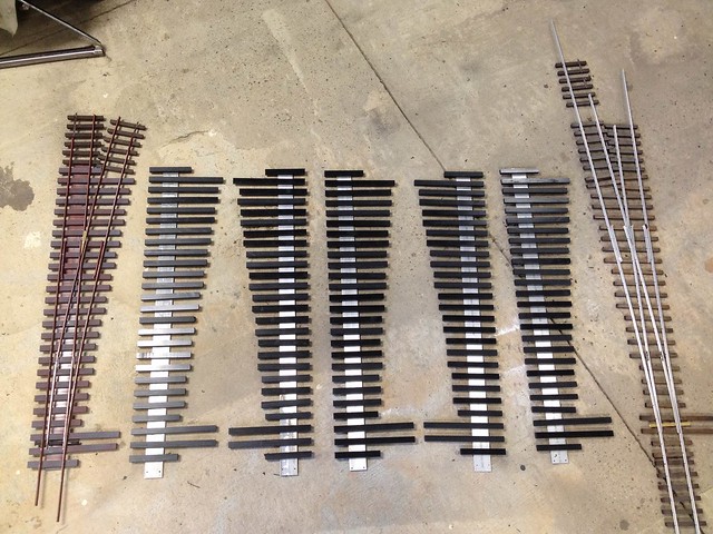
Finally what seems like some real forward progress. With the first switch done, I had the confidence to do a mass production type process. In the first photo You see enough tie to do 20 switches which should leave a few extra since the layout requires 18. They are all cut to length drilled and ready to attach to the base strip. Also pictured are 5 base stringers drilled and ready which is enough to open the main.
In the second shot I put the material in the first to use and now can show all the switches that will comprise the main in some degree of completion. Attending some family obligations right now, but when I get home we will see how fast I can spike…
Speed is nice Randy, but its accuracy that counts. The sample switch you brought over looked really good. Keep up that level of quality and you should be well on your way.
Good start! For some reason,I can’t do it that way. I cut a tie, splke it and then cut another one…(http://www.largescalecentral.com/externals/tinymce/plugins/emoticons/img/smiley-wink.gif)


