“if you ever get a chance to, read the Baldwin spec sheets some time.”
Can you expand on that? I’ve got the spec sheets for all of the EBT’s locomotives, but beyond stating tender wheel diameter, fuel and water capacities, material, and coupler height, (and the drawings to which the tank and frame are to be built), they’re quiet on much else pertaining to the tender. I know Baldwin’s tanks, frames, cabs, and other things were all done to set drawings with key dimensions coded by letters, and those letters corresponding to a chart that gave real measurements based on capacities, etc. I have drawings like that for tender tanks and locomotive cabs, but not for tender frames.
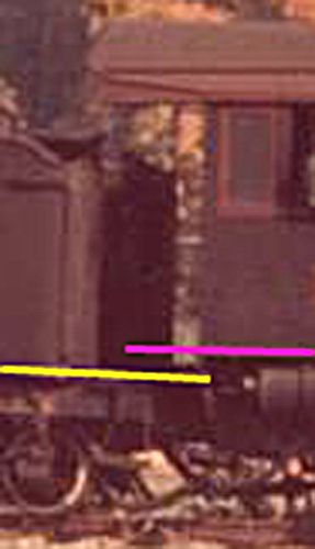
From what I know of the EBT’s tenders, each tender rode on a pair of identical trucks with identical-diameter wheels, and the beams making up the frame were the same thickness front to back. The decking is also the same thickness front to back, so if there is a designed-in forward pitch to the tender frame such that the tank slants forward, it would have to be at the bolster. If there is something built in to that end, it’s doubtful it’d be significant enough to show up in photographs–at least to where it could be attributable solely to that and not the weight of the fuel and water compressing the springs on the trucks front or rear. Quite honestly, in all the photos I’ve looked at and studied, I’ve never noticed any pronounced pitch one way or the other–at least nothing that jumped out at me.
“…+ a fat old man trying to shovel enough coal to feed the beast.”
I’d imagine after a few weeks of shoveling enough coal, the “fat old man” wouldn’t be quite so fat anymore.
Later,
K


