Hi
for those of you that intend to build an octagon roof, there is a YOU TUBE video on how to do it and how to calculate all of the dimensions. just enter “octagon rafter construction calculator”
there are several others on the subject.
Bill
Hi
for those of you that intend to build an octagon roof, there is a YOU TUBE video on how to do it and how to calculate all of the dimensions. just enter “octagon rafter construction calculator”
there are several others on the subject.
Bill
I would draw it out to scale… A top (plan) view and a side elevation view. Measure the Length of the base of the triangle from the plan view and the height of the triangle by measuring the Length of the sloped portion of the roof peak to eves . Note that the angle of the peak should be less than 45 degrees. I don’t mess with calculators and have more fun drawing to scale!
I had the same problem when I built 2 switch towers and had to put what is called a hip roof on them.
It is a 4 sided roof so building a 8 sided one is even harder.
Have you tried cutting out the form using paper or scrap pieces?
If it doesn’t come out exact you could use caulking or glue to seal up the miscuts then cover it with the corrugated tin or use wood shingles or tar paper.
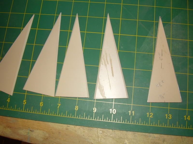
Here is the part I think you guys are missing. The angle at the peak doesn’t scare me. I can figure that out with paper by trail and error. I will probably do just this to get and idea of the height I want since I eyeballed the 2". But using 1/4 plywood which is what I was intending to use the edges where the eight panels join together need to be beveled so that they are flush with one another. the only reason this would be critical is at the end of the panel because the edge forms the fascia. Now using silicone to fill gaps is not a bad idea all around because I am going to use either foil tape for a tared tin roof or sand paper for a rolled asphalt roof. I suppose if I have to I can make a cedar fascia to cover gaps. I was just hoping there was a way to figure that bevel or some nice soul who understands sketchup or CAD would take pity on me.
I know with some fiddling I can get it.
Devon
When I did a water tank years ago, I first cut them square and then eyeballed the angle and made it a few degrees tighter because I wanted the surface flush, the underside not so much because of viewing angles. I’m guessing your angles are around 15*
Panels 4+" x 1.57" Geometry has the formula for the square of the rise and run divided by something too foggy froggy to remember. Trig is more about sine waves …
Half brain thinking, another cup o joe to go …
John
Devon, take a look at this video. It will either give you the info you are looking for or confuse the he77 out of you. There are two parts.
I guess it would help if I included both parts. Sorry.
Devon
In case you didn’t find the sheathing bevel angle in all those numbers,
here’s an easy way to do it.
You know that the bevel angle would be 22 1/2 degrees if you were building an octagonal box.
you also know that the bevel angle would be 0 degrees if the pieces were laying flat.
so in other words at 90 degrees to the horizontal the bevel is 22 1/2
and at 0 degrees to the horizontal the bevel is 0
so at 45 degrees roof slope the bevel would be half of ninety or 11.15 bevel angle
and at 15 degrees roof slope the bevel would be one sixth of 22 1/2 or 3.75 degree bevel angle
I think you get the idea how this works - - -
Bill
Yes bill that’s exactly what I was looking for.
So a 22.5 degree 1/2 turret with a 24/12 roof pitch which gables into a pair of cross gables at a 10/12 pitch should be beveled at whatever the sandpaper angle says when modeling it then?
Edit: Because this a yes or no answer
And for Rooster !
cluck
cluck
bwaaak
Devon, exactly the issue I had to deal with. After finding the correct angle, I made a bevel sled for my table saw to cut the wedges with the side bevels on them. My working water tank roof was (if I remember correctly) about 24" across, so any error was really apparent.
For as small as the size is, it just might be easier to cut the triangles, and then just belt sand the bottom edges of the ply wood till they fit. You would only have to sand 1/2 (every other one) to twice the single piece bevel degrees.
Is this roof going on a circle or on a square? If Circle, you must bevel the edges of the circular wall to get the top to seal around the roof where it joins the sides.
Dave,
I noticed the bevels you made in that other thread. Could figure out why until I thought about it then it made sense. This is going on a small round tank. was hoping since they are small that I can cut it on the compound miter saw. If not I like the sled idea. I also thought I could set up a jig for sand them on the belt or disc.
Devon Sinsley said:
Dave,
I noticed the bevels you made in that other thread. Could figure out why until I thought about it then it made sense. This is going on a small round tank. was hoping since they are small that I can cut it on the compound miter saw. If not I like the sled idea. I also thought I could set up a jig for sand them on the belt or disc.
Hi Devon,
Let me pop in here a minute. I’m the one that originally gave Dave a hand with his octagonal water tank roof and my cad drawings. Hard to believe it’s 3-1/2 years ago! When I used this cad system (MasterCam in my die sinking days), when we machined cavities in a die block, we didn’t have the luxury of cutting a little and trying that out. We had to cut it right the FIRST time or we could be scrapping a $50,000 to $100,000 piece of die steel!
When Dave told me what he wanted to do, I suggested drawing the roof pieces exactly how they would lay on the roof of the tank with all of the bevels and angles in place. Then it was just a simple act of rotating the individual pieces in a plane that was just like Dave’s table saw table. The mitre was set on the blade to the table and then the miter guide was set to that angle and he simply layed the roof piece in place on the saw table and made one cut…done and finished. What was great in working with Dave was that he REALLY understood how compound angles work AND had accurate measurements to give me. Compound angles can be a “mind twister” sometimes. What looks like a weird angle and couldn’t possibly work, actually fits just right. Two or three compound angles working together is very difficult to do. A change on any one of the three, can really make a big difference.
If you want to send me some drawings and some measurements of what you are trying to do, let me know. My email address is rmstd at earthlink dot net. I would rather do this by email rather than messaging through LSC because it is easier for me to attach the MasterCam drawings and other measurements you might need.
I’ll take you up on it Gary. I have options and a decent skill set. While I am no pro at compound cuts I am not s stranger to them either. These with be small pieces that will fit on my 10" compound miter saw. That’s how I want to cut them one and done. I also love an excuse to make a jig for the table saw so a sled is an option. One thing about a sled is I could use it to make s larger one as well.
I will email what I am after. Thanks so much
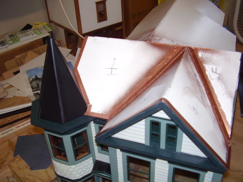
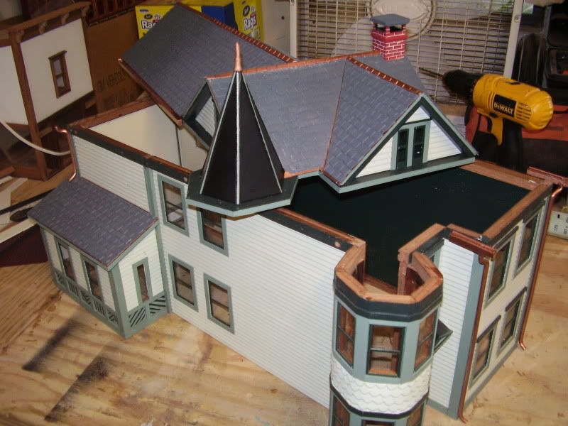
The witches cap I made was a bit easier as I used 1/8" pvc . Posting these for some inspiration as I understand it’s simple feat so I’m watching with interest as to how your project turns out.
Not certain if this will help but here is an Online Calculator. I guess that you could enter the values in 1:1 and then scale results as appropriate.
Roos if you keep posting motivational photos and I might have to give you a positive rep point. That is a nice building
It’s a model of your house isn’t it rooster?
Well a giant thank you to Gary for working this out in CAD for me. I have what I need now to cut it.