I understand, much of the fun is in the journey. The Cytron is an excellent driver at $10 isn’t it? I love that board. A guy over on the Facebook dead rail group turned me on to it. 13A of DCC is (way) more than enough for any of the large scale decoders, I have it in all of my locomotives now. I’ve tested it with QSI, SoundTraxx, TCS and the ESU xl5 decoders. Very tight DCC, it follows the logic input really well.
Martin,
The Cytron is working well for me!
I noticed that the battery monitor I linked to is no longer available. So I ordered one of these:
I’ll attach it to the diag mcu and should then be able to do all the calculations and display the same info on the diag OLED display. Or I might add this display for more bling:
Too much fun!
Seems like its taking forever - I keep re-doing one thing after another - keep adding features…
Have the basic 3 mcu system working, still on a power supply. Battery control is next.
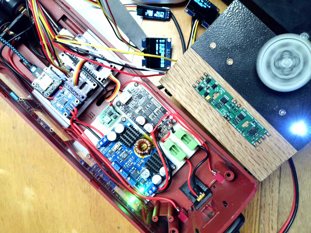
Here’s the electronics pod:

Note the new, larger OLED displays. The old one is in the center for comparison. Also added a display for battery voltage and estimated remaining charge.
Here is a closer view from the side:

They are mounted on this plate (which took me FOUR DESIGN CYCLES to get right!):

The battery manager will mount on the other side.
Steve said:
Seems like its taking forever - I keep re-doing one thing after another - keep adding features…
It’s never so much the destination, but its the journey, that’s the most fun.
O N L Y four??? I would be tickled if I could get a final design in four iterations at the office. Too many fingers in the pie. Nice word Steve
It’s alive!

This is a G-scale boxcar, with 6 26650 LiOn cells.
I still have to hook up a small 5v buck to power the mcus (they are now running off USB power, but that won’t work on DeadRail!)
Also need to print a panel to hold the 3 OLED displays. The battery monitor code has to be written…
I let the smoke out of the 1st battery manager I hooked up, and could find no reason why - hooked the 2nd one up identically, and its working properly. Must have been DOA…
Steve:
When you get this wrapped up would you be willing to give us some idea of the costs? Per controller, per loco electronics, etc.?
And it would be interesting to hear what the features are that you include vs other off-the-shelf options such as Airwire and Railpro if you know.
Cheers!
Jim,
If you go back a page or two you will see parts lists with links to a website selling each part in almost all cases.
I will do a summary page once complete, I guess I could do the as-built parts list & links there. I hesitate to give actual prices as with the supply chain being what it is today prices vary all over the board from one week to the next.
As to Airwire and RailPro, I know nothing about either of them. I suspect the big difference is that I am using mesh wifi for control, necessary because of the distances involved.
The track plan Good stuff on page 8 & 9 also.
I’ll be using a mesh network Wifi installation. Bluetooth just wouldn’t cut it.
If others want to actually build one from my design I will be glad to publish FreeCAD and kiCAD files.
I would also have to provide my rather extensive changes to DCC++EX.
Thanks Steve. Not trying to cause you more work. Prices will very much fluctuate, understood.
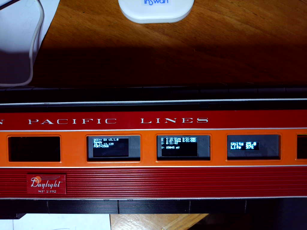
The display panel is printed. It will be exposed thru the boxcar door once I get the boxcar body mounted:
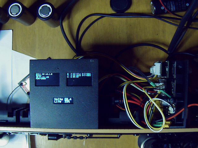
The top left display is for DCC++EX, showing status, wifi address and wifi port.
The top right display is for the diagnostics mcu, showing boot time, current time and uptime.
The lower middle display shows the current battery pack voltage and estimated remaining charge in percent.
It works!!!

MTH G-scale Coastal Daylight #99. set to DCC.
So now I need to design PCBs for the 2 feather connector boards…
Steve said:
It works!!!
MTH G-scale Coastal Daylight #99. set to DCC.
So now I need to design PCBs for the 2 feather connector boards…
Add a few lightning bolts and the quote “It’s ALIVE!” might be appropriate. (Apologies to Young Frankenstein)
Sent to fab:

The pc boards are due the 15th.
Started working on deadrail passenger cars for the Coastal Daylight twins:
Finished mcu holder in middle, starting on holder for the battery manager and motor board controller next.
A LOT more room in the passenger car vs. the BigBoy’s boxcar.
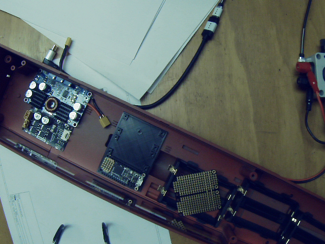
The PC boards arrived today, so I guess I need to put the carrier design aside and get back to the deadrail cars. Mounts for both battery manager and mcus finished and installed. Power switches and external connector installed. Battery holders installed.
Note the module between the mcu mount and the battery holder. This is an opto-isolated 10amp relay board. This will be controlled with an mcu digital pin, and drive a power bus for the passenger car lighting.

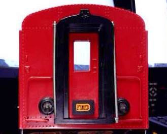
Got a new webcam, trying to set it up. So here’s a test picture of the passenger car switches and connector:
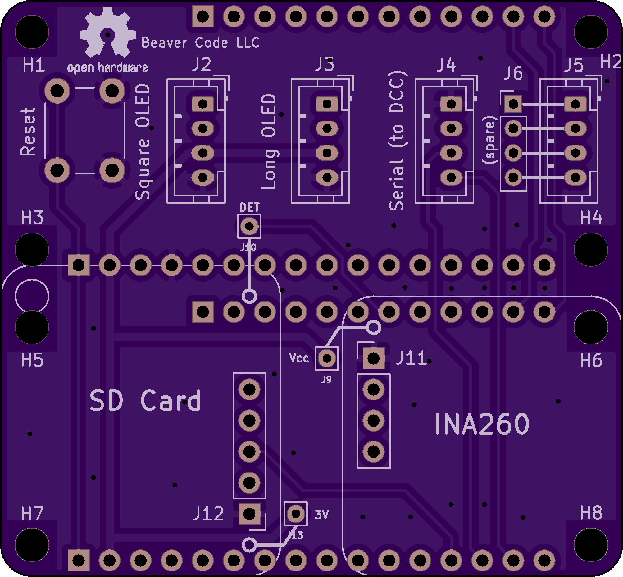
PCBs assembled, tested and working, no blue-wires (https://www.largescalecentral.com/externals/tinymce/plugins/emoticons/img/smiley-laughing.gif)

I previously decided to simplify parts by using the Feather M4 for both DCC and diag mcus. This meant I had to place an SDCard breakout on the diag PCB to replace the one that was on the Feather M0 Adalogger. This PCB also holds an INA260 breakout for the battery monitor software.
When I placed my first order for Feather M4s the standard M4 was unavailable, so I went with M4 CAN (CAN bus) versions. Now they are unavailable till end of Sept, so am going back to M4 Express for the 2 passenger DeadRails cars. The parts supply chain situation continues to suck…
Finished wiring, tested, WORKS!
So the next step is to design and print a display holder:
Steve said:
Finished wiring, tested, WORKS!
So the next step is to design and print a display holder:
That’s always the BEST part: It works! (Too many of my projects seem to never get to THAT stage!)
Congratulations!
Display mount installed:
Now to connect that opto-relay and the interior lights.