Heck of a day - smoked an mcu with a rookie mistake…
That set me back half a day…
But I did finally get the lights working:

Heck of a day - smoked an mcu with a rookie mistake…
That set me back half a day…
But I did finally get the lights working:

Some notes on the relay board I am using.
So there is ample 3.3v supply. But the pin current is too high. There is a 100 ohm current limiting resistor in the input circuit. It’s the part labeled “101” in the above image. It’s located between the input connector (VCC IN GND) and a jumper. Do NOT confuse with the other resistor labeled “102”, which is between the 2nd jumper and the relay. Replace the “101” resistor with a 330 ohm part. This reduces the drive current to 0.89mA, quite acceptable.
Another note. To attach the relay to the diag connector wing I used the spare 4pin grove connector.
I cut off one end and attached VCC, GND and pin 6 according to the standard color code. Just before plugging it in for the 2nd attempt (1st was the time I smoked the mcu/relay!) I noticed the wires on the grove end didn’t match the others on that board. Double checked, they sent me on pack of grove cables with the wires in reverse order on the connectors.
If I had powered it up that way I probably would have smoked a 2nd mcu… Changed pins to proper order on cable connector and all worked.
#4449 is on the road:
The Bigboy REALLY doesn’t like those R3 switches! I cringe every time I run him on the train room track.
His Dead Rail boxcar is complete:
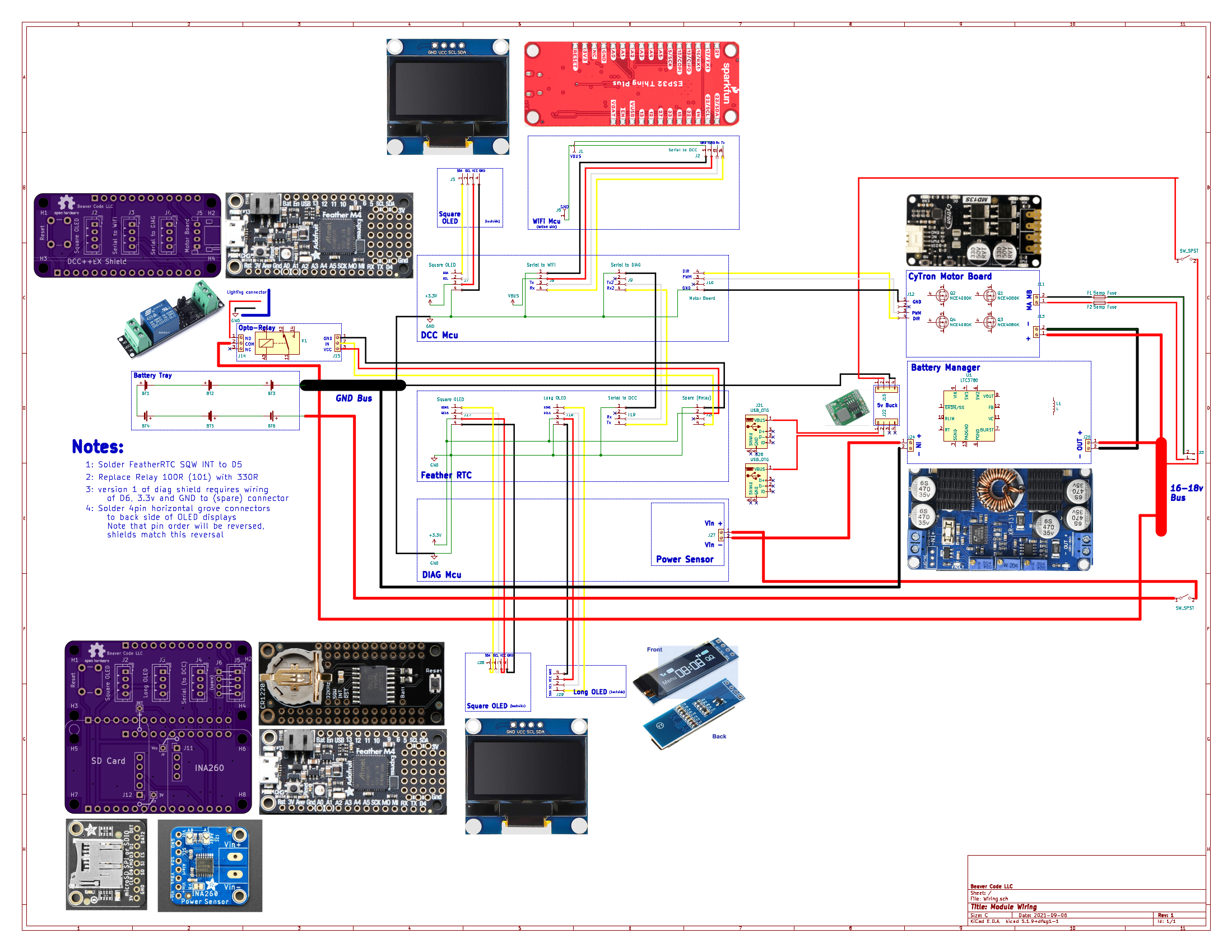
I created a “schematic” that shows the connections of the DeadRail system at the module level:

that is a tall antenna? no tunnels?
Jim,
It’s 4 -1/2", built the tunnels extra high knowing they would have to clear antennas: