Yea, I’m using them on connections that will be out in the weather all the time, like attached to the signals. I want the signals replaceable if one gets broken.
Bob McCown said:
Yea, I’m using them on connections that will be out in the weather all the time, like attached to the signals. I want the signals replaceable if one gets broken. And also for the 12v lighting bus to buildings.
I believe I have the HO prototype working, at least ARD thinks so:


In the right pic, on top of an HO passenger car, left to right:
- Adafruit DRV8871 motor board.
- Seeed XIAO SAMD21 mcu.
- ESP-01 wifi board.
A battery regulator & battery pack and its DeadRail.
Steve
I bought the cheapest 4 function decoder on Amazon. Worked right out of the gate, Headlight ON:

I’m using the fancier XIAO carrier, with builtin OLED. The XIAO is small, but at the cost of pins, and this carrier uses most of them up. To get a serial diagnostics port I am going to have to destroy the sdcard device (remove all its resistors and diodes). This will free up 2 pins that have a SERCOM behind their PADs.
600RPM 12V geared motor ordered, should give nice visual feedback of motor control.
Motor board and wifi mounted on common perfboard with the carrier. Worked out nicely!
Steve
Cool! When I was putting decoders in my N scale stuff, there was all sorts of “you must by high quality decoders!” noise, but I found the generic clone decoders (a few with sound even) would work just fine.
I mounted the decoder to a piece of oak, and printed a plate to mount 4 LEDS for headlight, backup light, F5 & F6.
It also holds the motor, which is doing 20mph in this photo:

It sits on top of the ARD case, and is expected to remain connected to the ARD, allowing sniffing of DCC packets at any time.
Next project for today is a small box with 3 sets of banana plugs and a double pole, double throw switch allowing fast change-over between the main track and programming track in the test setup.
That’s done:

So its time to put the beast into a case.
I found a beater in my junkbox. I believe it is a Hammond RMC Series box:

The additional parts needed (more or less):

Top row, left to right:
- Left Angle Micro USB extension cable (2)
- External Wifi antenna with uFL cable.
- 2 dual banana jacks + 2 fuses each - main/prog tracks - fuses on each rail.
- 110v cord receptacle.
Bottom row, left to right:
- Mean Well LRS-150-12 12V 12.5A power supply
- 3A 5V Step-Down Transformer Power Supply Module
- DROK Buck Boost Converter 5A Power Supply Panel
Other additional misc. thingies will be needed - TBD.
In this model I will be adding a 5V buck to power all three mcus. The 5V wire in the USB extension cables will be cut. This will make it impossible to accidentally power the mcus from both USB and the buck, which could harm one or the other… This also allows the mcus to run without any USB cables attached, important for wifi only operation.
The current plan to do this is mounting these dongles with a 3d printed plate on the back panel.
Then I will cut off the panel end of the USB extension cables to proper length and solder GND, D+ and D- wires to the dongle. The red wire (5V) will be capped with shrink-wrap. I will 3d print a bevel to hold 2 of the OLED displays on the front panel. One for the DCC++EX mcu, and a second for the diagnostics mcu. I’ve ordered a roll of dark gray filament for these bezels.
Hopefully it will come close to matching the color of the Drok buck regulator.
I have the boards fastened to the case’s chassis:

It’s cozy, but not overly tight. Screwed spacers to the individual boards and then used superglue to fasten the spacers to the chassis plate. Less work than drilling a bunch of holes, and easier to change if necessary.
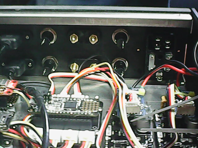
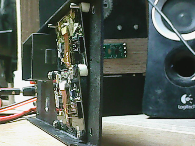
Looking at the inside from the front:

Again, clearances are just about right, room for ventilation, but not much wasted space.
Next step is to hook up the ps, bucks and 110V line (still using the external ps at this point).
That looks nice and tidy. I have some pc board standoffs with adhesive tape on one side, that I use to help me layout boards inside a case. Something like these.

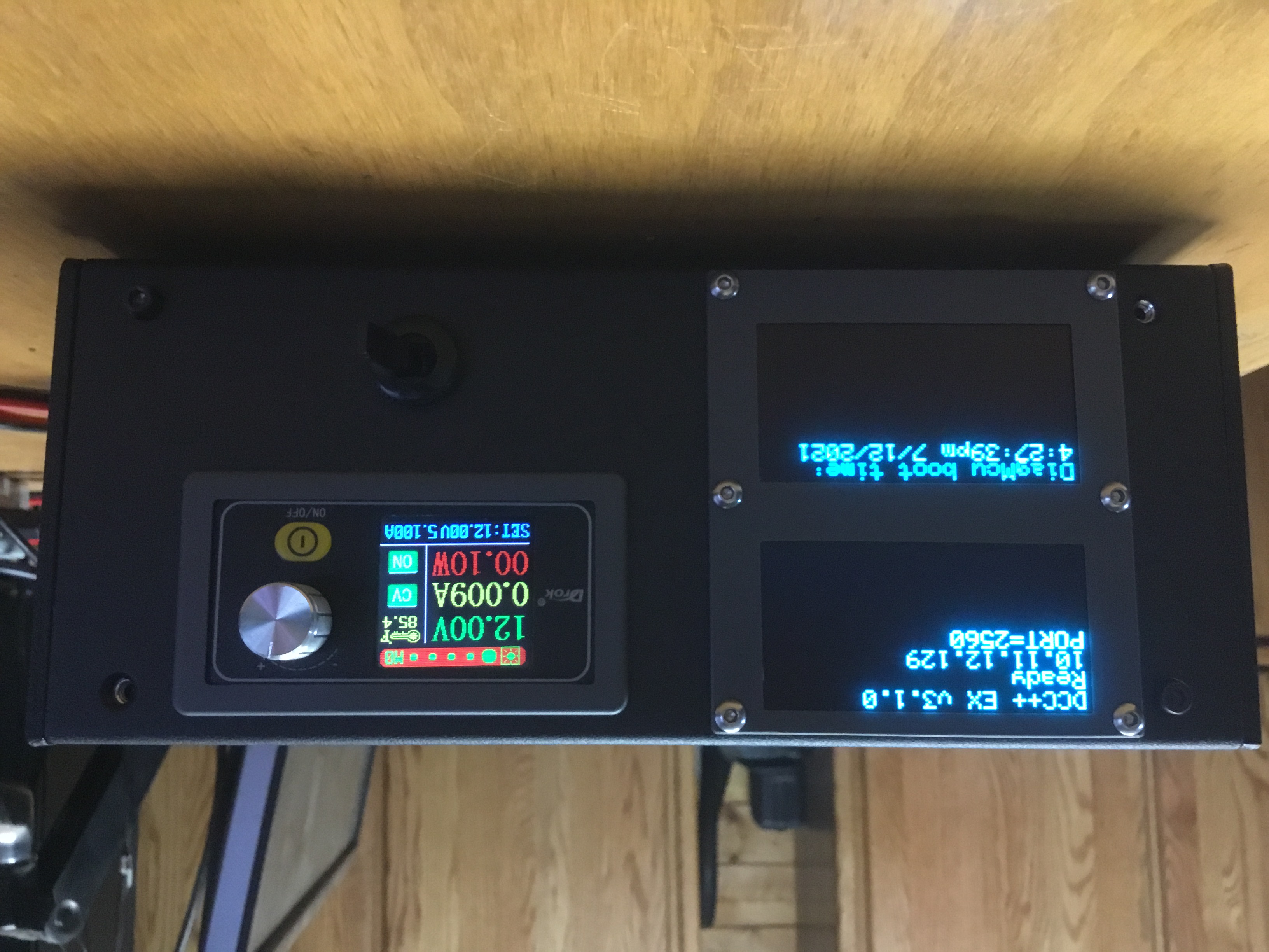
It’s now a self-contained (ie. no external PS, etc.) working unit:

It runs, reads & writes the test decoder.
Now come the part I like not so much - cutting holes in the front/rear panels to hold displays, switches and connectors.
The rear panel was a hopeless rats nest of holes, so I printed a new one:
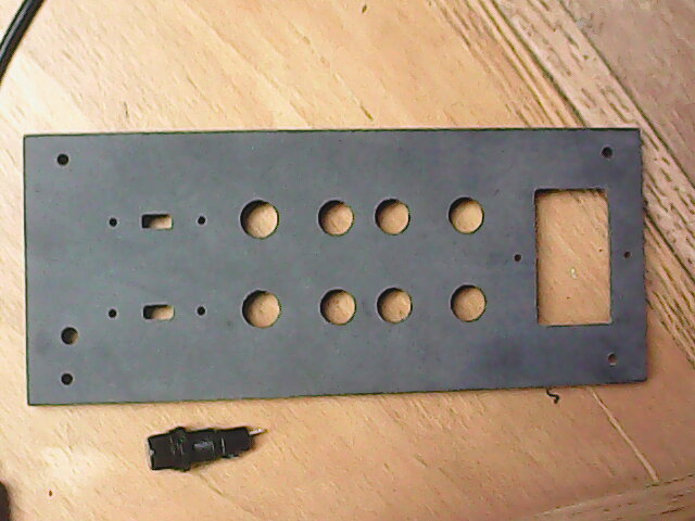
Populated, from the front:
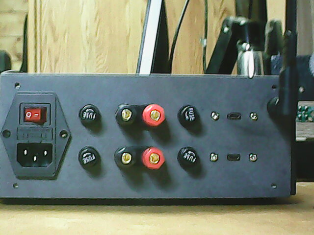
and from the rear:
Unfortunately my can of black powder-coat spray paint wont arrive till Thursday… guess I’ll work on the front while I wait.
I’m torn between these 2 for the front panel OLED displays:
The top one was epoxied then sanded down with 1000 grit sandpaper to remove the 3d lines.
It is definitely closer in color/gloss to the Drok buck regulator bezel…
The bottom one is unfinished - printed face side up.
Just had a brain fart thinking about where to place the mcu power switch on the front panel.
Bought one of these: what could be better!
I realized the reason I didn’t like either OLED bezel is that the scale is wrong, more bezel than display!
So I went looking for another display. I think this is it:

The original display is on the left. The bezel was out of scale because its circuit board is soldered to the OLED panel, so I had to cover the whole thing. This new one is made with the OLED glass separate from the pcboard, attached with a ribbon cable. So I hope to mount the OLED glass on the face of the front panel, and the pcboard on its backside, passing the cable thru a slot. There is also an issue with the height of the pcboard, but I think I can finesse that…
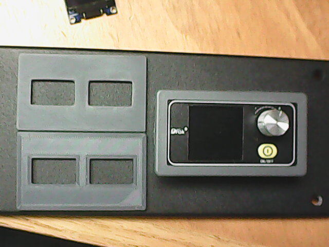
The front panel is finished:
The OLED pcboards wouldn’t stack vertically, so I tilted them back about 10 degrees and over-layed them a tad:
Even then they hit the top and bottom panels so I had to trim the spacers:
![]()
Now I need to paint the 3d printed backpanel and assemble/wire.
Looks great!
(Too much fun? (https://www.largescalecentral.com/externals/tinymce/plugins/emoticons/img/smiley-foot-in-mouth.gif))
Closing Thoughts.
===========
The cabinet:
I used something from my junk box, it turned out to be almost perfect in size. It is a 2U, half wide rack cabinet, ie. 8.5" x 8" x 3.5". It would have been better if it were 4" high to accommodate the display boards. Plan the front/rear panels before making a final choice, the panel layout is the most critical, there was more than enough room for the electronics. An alternative design would eliminate the internal power supply, instead using a 12v barrel jack on the back panel.
=========
The mcus:
The Feather based design has worked out VERY well. Much smaller than the Mega2650, and also more than enough eprom/ram. The Mega2650 runs on the edge… The use of the Particle Mesh grove connector baseboard kept the wiring clean/manageable. I wouldn’t bother making a custom board unless I needed to make dozens of these.
The use of the SparkFun ESP32 ThingPlus with external uFL antenna connector is working flawlessly. Loading the required ESP32 WiFi server code is straightforward.
The addition of the 2nd Feather (M0 Adalogger) for diagnostics was a worthwhile effort. I plan to use it on the DeadRail cars, writing output to the micro SDCard.
I wouldn’t bother using the Adafruit Grand Central board in a base station unless I was planning on controlling a lot of signals/switches/lights. It does have the advantage of more memory and connectivity than a Feather.
The use of an Arduino Mega/Uno is a dead end, don’t bother. (<<< personal opinion)
================
The motor boards:
The CyTron MD13S works well, but required external current sensing. Its my choice for the DeadRail cars as it is single channel, no unneeded hardware.
The Seeed 5 amp 3.3v bidirectional current sensor fills the sensor void. Mounts well to top
of the CyTron. The bad news is (from Seeed website):
Estimated to ship on 2022-04-24 at the latest.
===========
Other parts:
The Drok buck/step regulator works well.
The XT30 connectors scale/fit effectively.
The larger OLED displays are perfect for a tabletop controller, but would be
too large for a DeadRail car.
===========
Other tools:
The ARD-DCCSHIELD from Iowa Scaled Engineering was helpful for debugging the system. I did have to add a 330pF cap between the 2 inputs to make it work (undocumented).
The cheap decoder I set up was also very helpful. If I had used my real loco in the beginning I might have shelled it as the code was doing VERY BAD things early on.
A good scope is desirable.
===================
What I would change:
I should have placed an Ethernet connector on the back panel.
Find myself reaching for the mcu reset switches when developing sw, but they are now
hidden inside the cabinet. Will be placing a pair of reset switches on the front
panel soon. Probably not useful for most users…
I left off some of the stacking pins on the wifi and diag mcus, soldering the serial
port cables directly to those positions. The FeatherWing RTC board that the M0 mounts
on has a row of solder points directly inside each of the stacker pins. Likewise,
the FeatherWing Proto board that the SparkFun mounts on has such solder points.
I would install ALL stacker pins on both the M0 and SparkFun boards, and solder the
serial cables to the mounting boards. This would leave the 2 mcus unencumbered
with cables.
Ability to see some of the status LEDs would be nice, light tubes perhaps?
I really see no need for current sensing on the main track. A pair of quick-blow fuses
on both rails is more reliable: KISS
Accurate current sensing IS necessary for the programming track. Another advantage of the Feather here is that it has 12 bit ADC resolution vs. 10 bit on the Arduino. This is even more important with the 3.3v ADC range of the Feathers.
So now I build the deadrail version.
The parts:
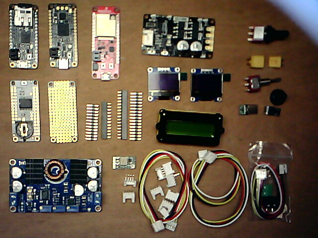
Top row, left to right:
- Adafruit Feather M0 Adalogger for diagnostics
- Adafruit Feather M4 Express, runs DCC++EX
- SparkFun ThingPlus ESP32 for wifi
- Cytron motor board
- Power switches (2)
- XT30 power connector (1 pair)
Middle row, left to right:
- FeatherWing precision RTC, used to timestamp diagnostics
- FeatherWing protoboard, used to mount Feather M4 Express
- SHORT Feather headers for Feather M4/M0 (2 sets)
- SHORT Feather pins for Feather M4/M0 (2 sets)
- OLED displays (2), for DCC++EX and Diagnostics mcus
- Battery monitor
- Power switch rubber sleeve (2)
- USB type-c dongle
- USB micro type-b dongle
Bottom row, left to right:
- Battery manager for track power
- 5V buck regulator for mcus
- Horizontal grove connectors (7)
- Misc. grove cables, various lengths TBD
Not in picture:
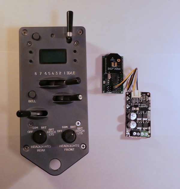
Man, that is a lot of parts. Here is my complete dead rail system excluding the battery and decoder. I didn’t think I would like the PT at first, it’s kinda pricey, but I’ve grown to love the thing.
Martin,
Yes it is. I’m going for the Cadillac of deadrail controllers.
It could be reduced to just the Feather M4, the Sparkfun ESP32, the Cytron motor board, and the battery manager.
But what fun would that be?