The board is coming along quickly.
The front:
And the back:
Steve
The board is coming along quickly.
The front:
And the back:
Steve
I have started the configuration of a Feather TripleWing to a prototype of the DeadRail DCC++EX controller. I discovered that it is meant to be used as a “horizontal stacker”, ie. all the lines between the 3 sections are connected in parallel, as if they were connected by stacking. Eg. the tx line is connected on all 3. Can’t do this when all 3 boards are mcus… So the first thing I had to do was route a channel (top & bottom) between the 3 sections, effective y cutting all the connections between sections. At this point the mechanical work is done. Next step is to run all the wires. Note that I only placed sockets for the actual pins I will be using (plus corners for stability). This give me wide alleys to run the wire thru.


Steve
I’s alive!!!

Steve
Nice! Always fun when something works as designed. I always sweat when I order custom boards, and have to assemble one to see if it actually works (even if I’ve breadboarded it and prototyped it)
Since there has been a lot of discussion lately on the DCC++ , I thought I would show you what i have whipped together. This is all based of the work Dave Bodnar’s from Trainelectronics.com had developed. I just took it a little further by using a smaller Arduino and make a custom circuit board to hold everything except for the motor controller. Instead of using the Arduino Uno or Mega like most with motor shields, I wanted to be able to make it small enough for everything to fit in a Bachmann Bog Hauler Tender under the coal load leaving the inside of the tender for a lith-ion battery. I used the Arduino Nano, a HC-12 transceiver module and the VNH2SP30 Motor controller as well as a DFPlayer MP3 module. I designed a PC Board using ExpressPCB (or was it PCBExpress) software and then had them custom made 5 boards for me. I designed the board in such a way that the board could be used in the transmitter or as a receiver in the tender, depending on what components were installed on it and where. It worked out great not having to have two different board to design and order. Dave Designed his Hand held controller in Coreldraw and laser cut the parts to make it. I went a different route and found a company (Pactecenclosures.com) that makes the case for hand held controllers and bought a couple of them. they were only about $12.00 and looked great and had the mouthing posts in it already to fit the board I designed. I ordered model TT-9VB/2AA which was the perfect size for the wireless throttle. After I had all the electronic parts which all were order off ebay to get the lowest prices. I waited a week before all of them arrived. By then I had the circuit boards in hand and started putting it all together. It took about an hour, then I downloaded the Arduino code from Dave Bodnar’s website and uploaded it to the Arduino Nano. Everything worked perfectly. The throttle worked just like Dave’s did on his website. After building a second board to be the receiver, I wired it into the tender with the on /off switch, binding button and well as the battery charge/track power switch. Plus I added wires to connect the Headlight, Marker lights, cab light and Firebox light. The DFplayer module was also added. but have not created the sound files as of yet. After everything was connected, I tested the system on my indoor 1:20.3 scale layout and it worked great. The only things I dont like about it is that I have to use a binder button to connect to the throttle. I would like to find a way to hard code the loco number in the software when its uploaded to the receiver Nano, so all I had to do was turn the loco on and then select which one I was to run from the throttle. The Throttle is set up to operate 4 engines at the same time. I would also like to figure out how to put code in the software to make the DFplayer module play the whistle sounds automatically when the engine goes forward as well as in reverse per prototype practices. I also need to add some caps to the motor to reduce the motor whine from the ESC controller. You can see how I built it with photos and video on my website at http://www.danstrains.net/wireless_dcc_plus_plus_system.html
Dan Stuettgen
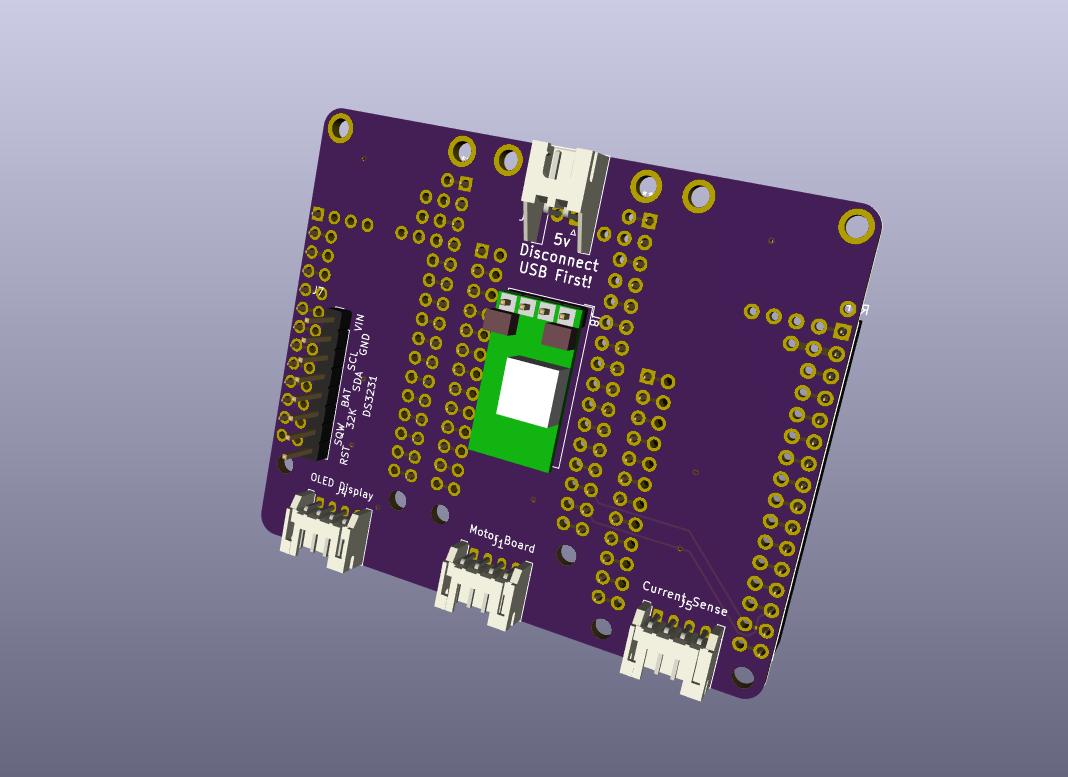
So having worked with my new board for a day I’ve come to realize it was the wrong approach.
It is a brick 3 feathers wide and 2 high. Ponder this:
This would stack on TOP of the Feather M4, bringing out connectors for every thing. The Sparkfun ESP32 wifi mcu would not need a board below it, and could be positioned where ever it worked out best. Probably attached to the inside roof of the boxcar so that when removing the body for a battery change there would never be stress on the antenna cable., only on the serial port connecting it.
Likewise, the diagnostic mcu could be somewhere else, and again wouild need no board below it as in the 1st design. So now we have 1 wide x 1 high (wifi), 1 wide x 2 high (M4 + this board), and 1 wide x 1 high (diag mcu). So a savings in space of 2/6 = 1/3. Plus a lot more flexibility!
I also have realized this could be a nice table-top controller, so I’ve added motor board control and current sense for a programming track.
First thing to do is see if I have enough pins of the proper types to do all this (pretty sure I do). Once I can see them on the scope I’ll do a prototype with a Feather Wing Single.
Steve
So searching for grove connectors I found this:
Adafruit/Seeed grove connector board.
I think it does everything my above prototype does **without any cutting or jumpers **
Just ordered one - 7 days…
Steve
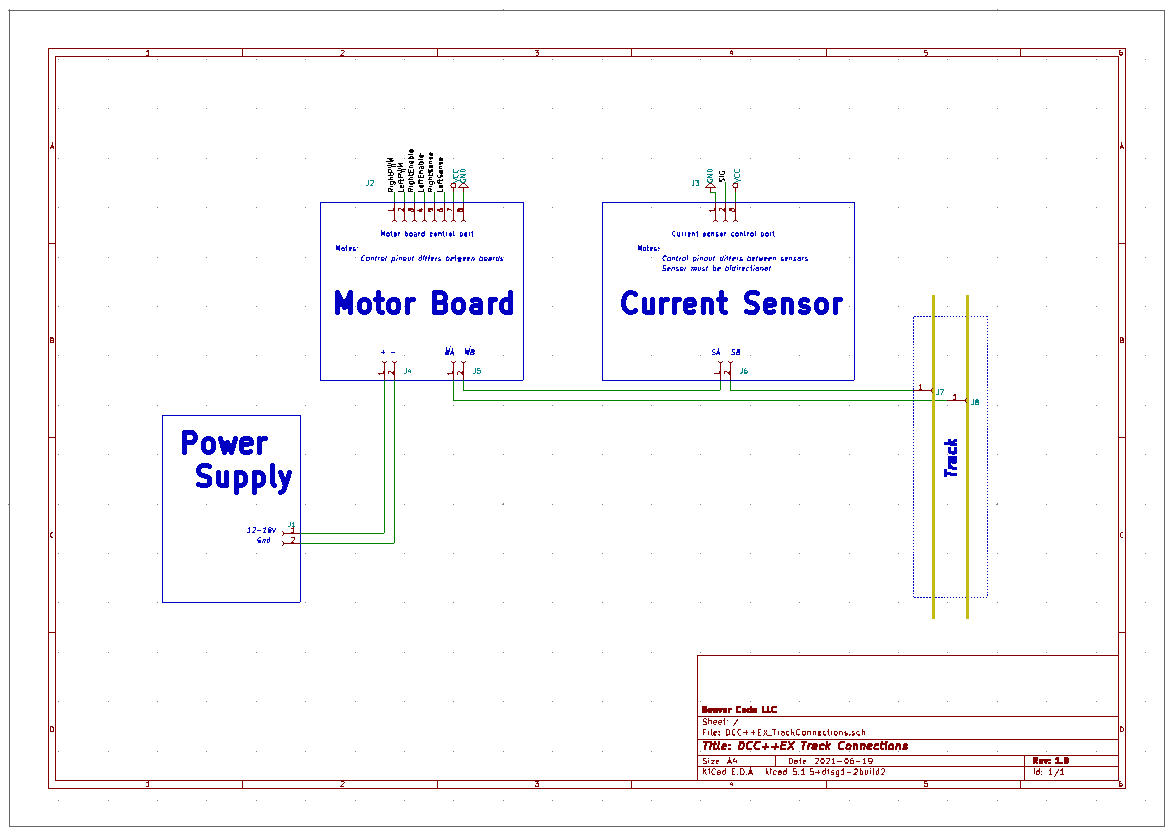
I had a major misunderstanding of the way current sensing is used. I thought I could just place a sensor in the input ps path to determine when there is a short/overusage of some sort.
Turns out it HAS to be in the track side of the circuit to allow the programming track sw to detect the small current draw the loco uses to signal an ACK.
This means it HAS to be a bi-directional sensor (eg. an AC sensor). So I have changed my spec to use this ±5A DC/AC Current Sensor.
This is my understanding of how it all hooks up:
Steve
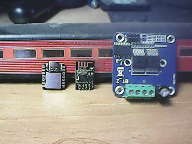
Got HO deadrail?
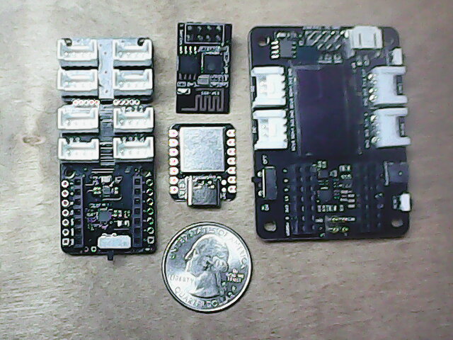
The carrier on the left has a snap-off end so that you can use it with only 4 grove connectors.
The mcu in the bottom middle is a SAMD21. The module above it is the ESP-01 wifi unit.
The module on the right is a more full-featured carrier with an OLED display, RTC and micro sd card holder.
I plan to use that for development, but is probably more card than you would want to put in an HO boxcar.
Any suggestions for a motor board of HO stature? It has to use 3.3V control signals.
Steve
I think the IBT-2 board is the smallest motor board I’ve seen.
https://www.ebay.com/itm/133623501532
Judging by the screw terminals, I’m guessing an inch square-ish.
Bob,
Unfortunately its 2" square:
Steve
Hmm
Digikey lists this one
and this one on Adafruit
Bob,
The pololu looked good but :
Motor supply voltage: 0 V to 11 V
The Adafruit 3190 looks possible, a pic on the site shows it to be the size of a quarter:
6.5V to 45V motor power voltage
Up to 5.5V logic level on IN pins
565mΩ Typical RDS(on) (high + low)
3.6A peak current
PWM control
Current limiting/regulation without an inline sense resistor
Undervoltage lockout
Overcurrent protection
Tiny circuits is out:
Note: Although the DRV8837 is rated at 11V at 1.8Amps, with the small size and small heatsinking, we do not recommend exceeding 5V at 500mA
I spent the last couple days printing 3D bezels & cases, things were getting very disorganized!

Upper left is the PS. A buck for 5V to mcus, and a 2nd buck/step to provide 12V - 18V for motor boards.
12V/12A PS in back of case.
Lower left is a mega + ARD board, banana plug connector for motor board/track connection,
Far right is a small bezel holding an OLED.
Now I can move these devices around from prototype to prototype without it being a major pain.
Steve
Addendum: 7/19/2021:
The tabletop Command Station is (more or less) complete.
See the post dated 7/19/2021 for changes & details.
-------------------------------------------------------------------------------------------------
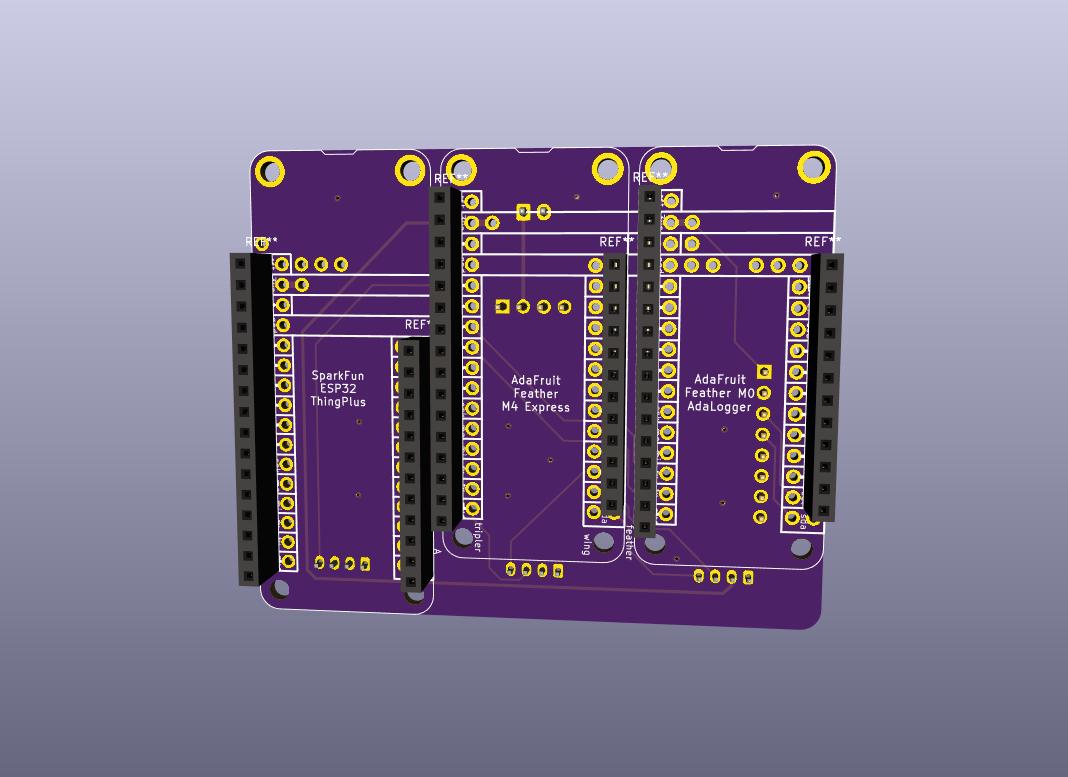
So now I begin the next prototype: An (almost) completely plug-together table-top command station.
The parts:

Top row, left to right:
±5 volt bidirectional current sensor for the main track.
Cytron motor board for the main track.
Adafruit Feather M0 Adalogger for diagnostics.
Adafruit Feather M4 Express, runs DCC++EX.
SparkFun ThingPlus ESP32 for wifi.
Middle row, left to right:
±5 volt bidirectional current sensor for the programming track.
Cytron motor board for the programming track.
FeatherWing precision RTC, used to timestamp diagnostics.
Seeed feather grove shield to hold the Feather M4 and provide connections to everything else.
OLED display, for DCC++EX.
Bottom row, left to right:
Grove cables: both sensor and motor board come with.
Additional 1 & 1/2 doubled ended cables (full cable will be cut in half).
There will be pins to solder to several of the feathers, as well as the cut ends of the grove cables to solder to feathers and OLED. Oh, and high current connectors to the motor boards, I use Amass XT30s.
Still, 90% of the sweat is eliminated by the grove connection system. And it should be much more reliable than making all those connections with solder-tacked wires.
Stay tuned…
Steve
Addendum: 7/19/2021:
I suggest installing all the pin header pins on both the M0 and ThingPlus.
See the post dated 7/19/2021 for details.
-------------------------------------------------------------------------------------------------
The assembly of the 3 Feathers is complete.
I’ve added a FeatherWing proto board to the parts list. It’s used as a mounting plate for the Sparkfun ESP32.
You could also use a chunk of standard proto board, its not used for connections.
Headers are soldered to both this FeatherWing and the FeatherWing RTC board:

Pin headers are soldered to the Feather M0 Adalogger. Note that pins GND, RX & TX are left empty for the grove cable.
The cut ends of a grove cable are soldered to:
Note: DO NOT USE the RED wire! The Diag feather is powered thru it’s USB cable.
I remove it from the grove connector to be safe…
I use a dab of superglue to dress the cable to the bottom of the board.

Pin headers are soldered to the Sparkfun ESP32. Note that 5 pins on the left side and 4 pins on the right side are left empty.
The cut ends of a grove cable are soldered to:
Note: you MUST NOT plug a cable into the USB connector of the Sparkfun ESP32 while it is attached to the grove shield via this cable as its circuitry isn’t happy when fed 3V3 from both its onboard regulator and the Feather M4 via the grove cable!!!

The cut ends of a grove cable are soldered to the OLED display:


Fasten the grove shield, RTC Feather and and Wifi proto board to a base as appropriate.
Install the Feather M4 into the grove shield.
Install the Feather M0 into the RTC Feather. Plug it’s grove cable into the grove shield’s A2 (A2/A3) connector.
Install the Sparkfun ESP32 into the proto board mount. Plug it’s grove cable into the grove shield’s UART connector.
Attach an antenna to it’s uFL connector.
Plug the grove cable from the OLED display into either I2C connector of the grove shield.

Output of DCC++EX:
DCC-EX V-3.1.0 / FEATHER_M4
<* LCD0:DCC++ EX v3.1.0 >
< LCD1:Starting >
< ++ Wifi Setup Try 1 ++ >
< Wifi Check: [+IPD\0] >
< TIMEOUT after 200ms >
< Wifi Check: [\r\nOK\r\n\0] >
\r\nOK\r\n< Found in 2ms >
< Wifi Check: [\r\nOK\r\n\0] >
\r\nOK\r\n< Found in 2ms >
< Wifi Check: [\r\nOK\r\n\0] *>
AT+GMR
AT version:2.1.0.0(883f7f2 - Jul 24 2020 11:50:07)
SDK version:v4.0.1-193-ge7ac221
compile time(0ad6331):Jul 28 2020 02:47:21
Bin version:2.1.0(WROOM-32)OK
<* Found in 16ms >
< Wifi Check: [\r\nOK\r\n\0] >
AT+CWJAP_CUR?\r\n\r\nERROR\r\n< TIMEOUT after 2000ms >
< Wifi Check: [\r\nOK\r\n\0] >
AT+CWMODE=1\r\n\r\nOK\r\n< Found in 4ms >
< Wifi Check: [\r\nOK\r\n\0] >
AT+CWJAP=“AAA”,“BBB”\r\nWIFI DISCONNECT\r\nWIFI CONNECTED\r>
< Wifi Check: [+CIFSR:STAIP\0] >
AT+CIFSR
+CIFSR:STAIP< Found in 4ms >
< Wifi Check: [0.0.0.0\0] *>
,“aa.bb.cc.dd”
+CIFSR:STAMAC,“aa.bb.cc.dd.ee.ff”OK
<* TIMEOUT after 1000ms >
< Wifi Check: [\r\nOK\r\n\0] >
AT+CIPSERVER=0\r\n\r\nOK\r\n< Found in 9ms >
< Wifi Check: [\r\nOK\r\n\0] >
AT+CIPMUX=1\r\n\r\nOK\r\n< Found in 3ms >
< Wifi Check: [\r\nOK\r\n\0] >
AT+CIPSERVER=1,2560\r\n\r\nOK\r\n< Found in 8ms >
< Wifi Check: [IP,"\0] >
AT+CIFSR
+CIFSR:STAIP,"< Found in 4ms >
aa.bb.cc.dd"< LCD4:aa.bb.cc.dd*>
<* Wifi Check: [\r\nOK\r\n\0] *>+CIFSR:STAMAC,“aa.bb.cc.dd.ee.ff”
OK
<* Found in 4ms >
< LCD5:PORT=2560 >
< Wifi Check: [\r\nOK\r\n\0] >
ATE0\r\n\r\nOK\r\n< Found in 2ms >
< ++ Wifi Setup CONNECTED ++ >
< MotorDriver ** WARNING ** No current or short detection >
< MotorDriver ** WARNING ** No current or short detection *><* Signal pin config: normal accuracy waveform >
< LCD1:Ready >
< LCD2:Free RAM=187325b >
< LCD2:Free RAM=187181b >
< LCD2:Free RAM=186877b *>
Output of the diag mcu:
DiagMcu boot time: Thursday 9:09:34am 6/24/2021
Current temperature: 77.0F
read USB - write to serial1
read serial1 - timestamp & write to USB
Thursday 9:09:42am 6/24/2021 -
Thursday 9:09:42am 6/24/2021 - >>>
Thursday 9:09:42am 6/24/2021 - DCC-EX V-3.1.0 / FEATHER_M4
Thursday 9:09:46am 6/24/2021 - MotorDriver: power pin: 4, signal pin: 5
Thursday 9:09:46am 6/24/2021 - MotorDriver: power pin: 6, signal pin: 9
Thursday 9:09:46am 6/24/2021 - DCC++EX Ready
Thursday 9:09:46am 6/24/2021 - Free RAM: 187325 bytes
…
Motor boards are next…
Steve
I’ve put together a motor board with current sense.
I soldered a female XT30 to the motor board’s ± pads and the + terminal of a male XT30 to the motor
board’s MB pad, in an upright position. I soldered one 18 gauge wire to the motor board’s MA pad and another to the - terminal of the male XT30:

I stripped insulation from some 18 gauge silicone wire and placed it over the 2 bare wires previously soldered to the motor board. I then removed the screw terminal block from the sensor. Dressed the wires so that they pointed up and went thru the connection holes of the current sensor. Used a little hot melt glue to fasten other end to the 2 large caps on the motor board. Finished by soldering the 2 wires to the sensor.

First try the power enabled LEDs kept flickering. Thinking it was a short I tore it apart and re-tested step by step… Turned out to NOT be the circuit, but that the over-current sw shutting down the power… So now I need to figure out what I am doing wrong in the code.
Steve
I like those XT30 connectors. I’ve been converting most everything over to WeatherPack connectors myself, but the XT30s look neat for on-board plugs.
Bob,
I’ve seen those connectors on cars, but never thought about using them on locos. Might be useful for my turnout servos, ie. things that stay out in the weather.
Figured out what I was doing wrong in my code, had the pin mappings from my translation of the schematic for the grove shield mixed up. The correct config.h entry would be:
#define DEADRAIL_MOTOR_SHIELD F(“DEADRAIL_MOTOR_SHIELD”),
new MotorDriver( 6, 5, UNUSED_PIN, UNUSED_PIN, UNUSED_PIN, 16.113, 5000, UNUSED_PIN),
new MotorDriver(10, 9, UNUSED_PIN, UNUSED_PIN, A4, 16.113, 2000, UNUSED_PIN)
The main track motor board control cable plugs into Main, aka. D2 (D2/D3).
The main track current sensor plugs into Mcurr, aka. A0 (A0/A1). [unused at this point]
The programming track motor board control cable plugs into Prog, aka. D4 (D4/D5).
The programming track current sensor plugs into Pcurr, aka. A4 (A4/A5).


Steve
