Large Scale Central

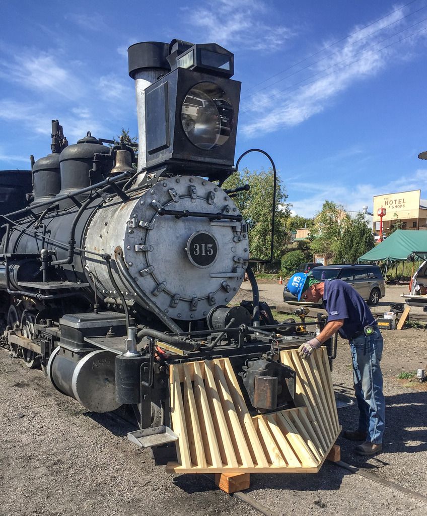
D&RG 315, My week in Silverton

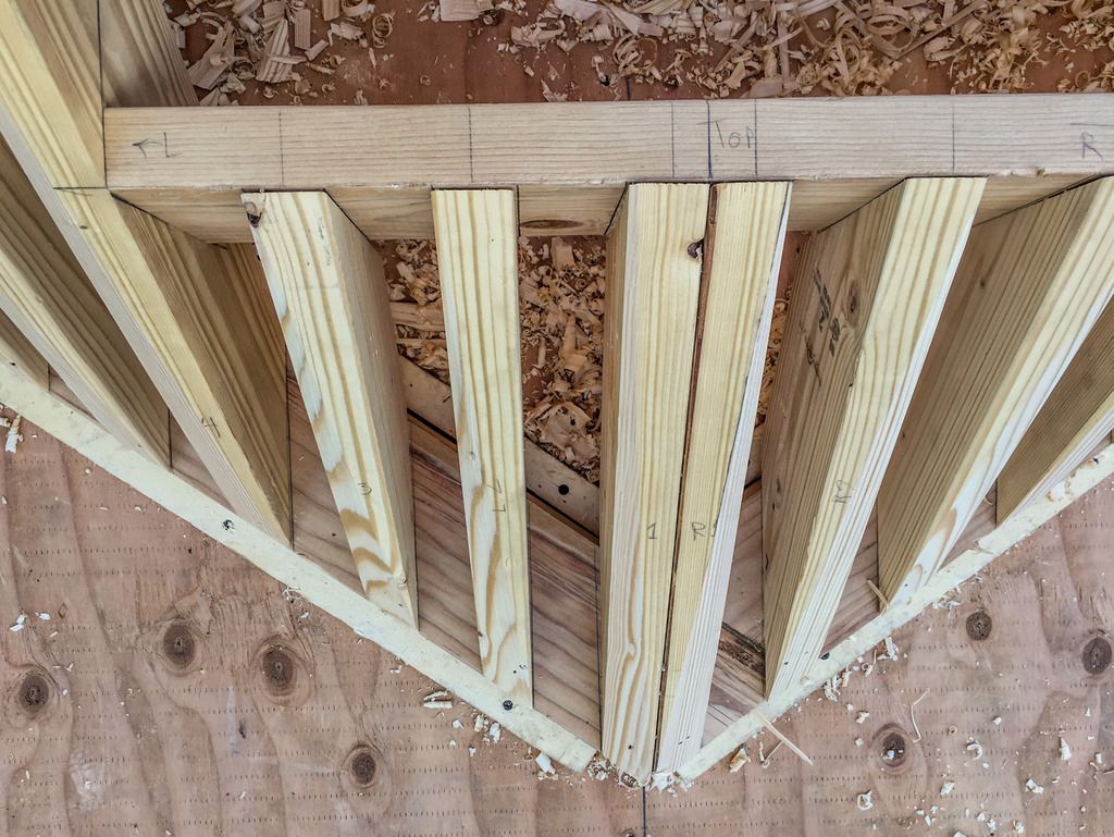
Got to start to actually build this thingie. Laid out location lines for the top boards to match the bottom board. To keep the Pieces in registration to each other thru out the build, I screwed the top boards to the jig, After drilling access holes thru the jig to let me screw the vertical boards to the top boards.
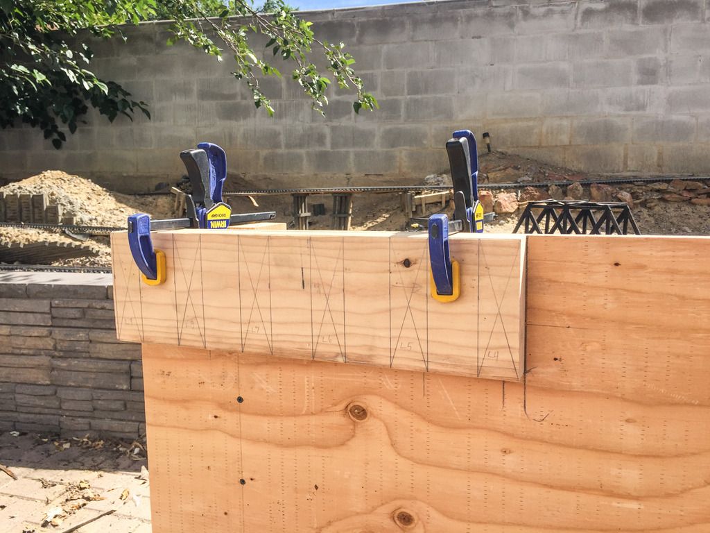
The small holes are for screws, and the larger holes are for dowelling.
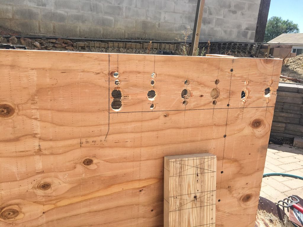
I located the bottom board to its required position, and attached guides to hold in place, to keep it in registration on the jig.

Now with the top and bottom boards in alignment, and in correct placement to each other, I could now get a correct measurement for the length of each vertical board.
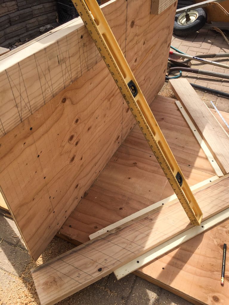
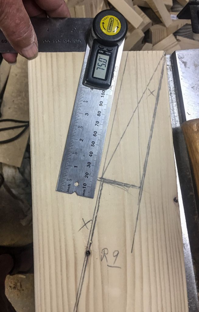
And by fixing a straight edge from top to bottom, I can measure the angle to cut to get a perfect fit.
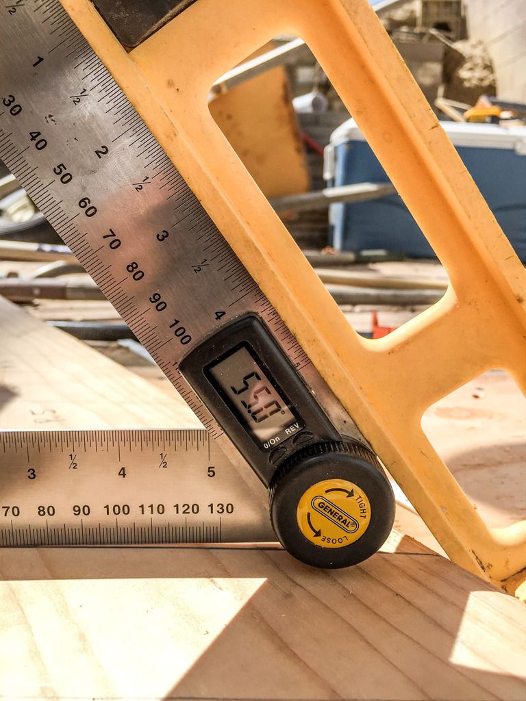
Because the top board is vertical and the bottom board is horizontal, and in a “V” shape, every board is a different length, and the angles likewise change , top and bottom, on every vertical piece.
Measure twice, and cut once, rule really applies here.

The Right and Left sides are mirror of each other, So I can cut and build both sides at the same time, or mess up both sides the same…

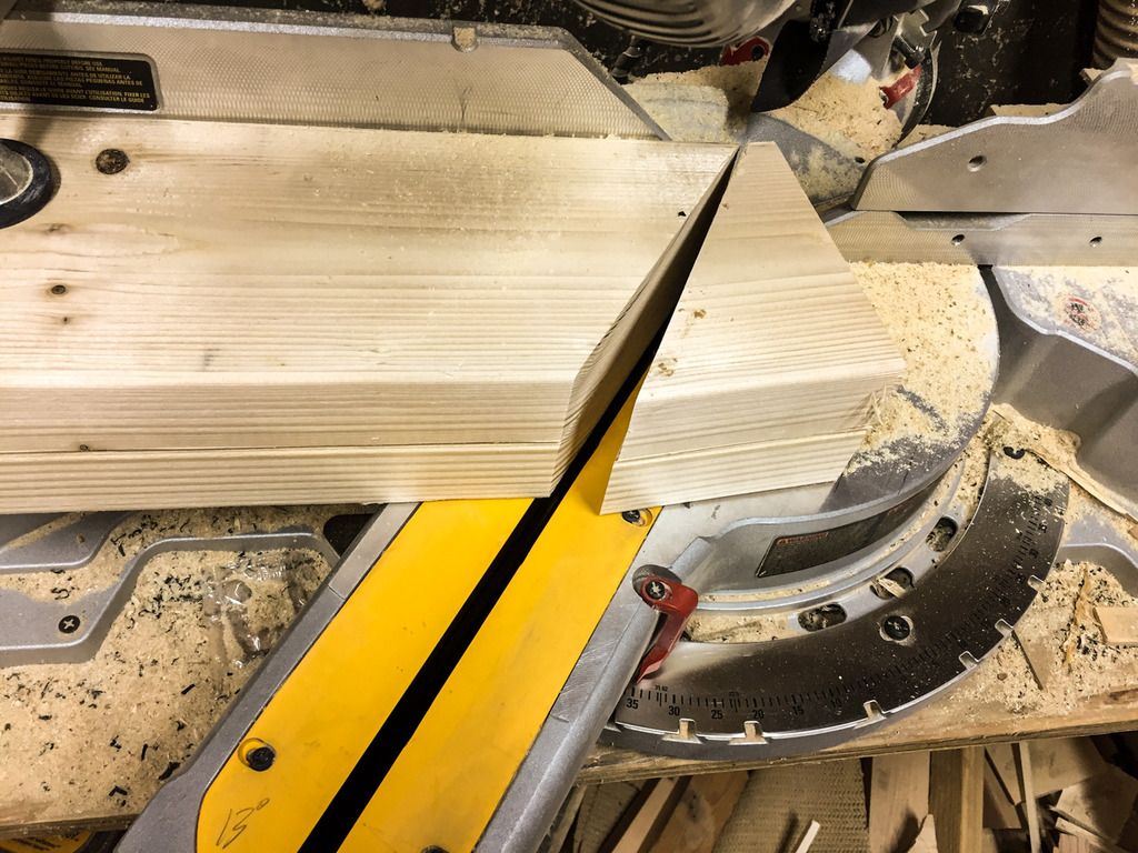
Started with two pieces of 2x6 lumber, and cut to length, and then cut the first end to the required degrees on the miter saw. and then the reciprocal degree cut to equal 90 deg on the other end.
Got the first two center boards attached, that make up the sides of the knuckle pocket opening.
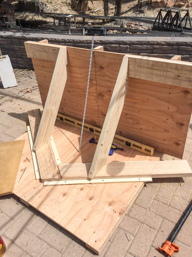
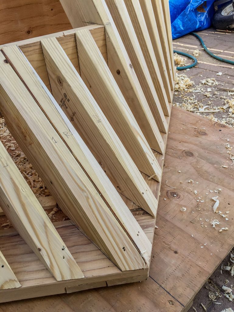
Notice that the vertical board front edge hangs over the bottom board on one corner. This overhang will be planed off latter to match the “v” angle of the bottom board.

Cut and laid out the center board, that will hold the tops of the middle boards below the knuckle pocket. Pre drilled and set the screws ahead of time due to clearance issues with the jig.
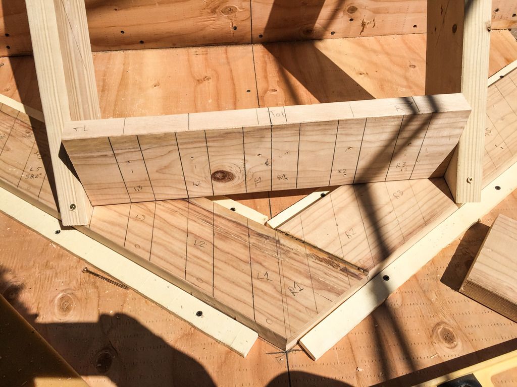
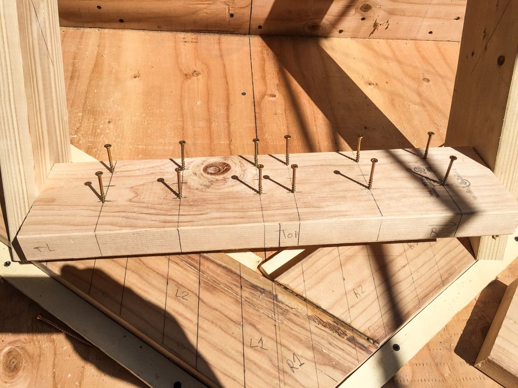
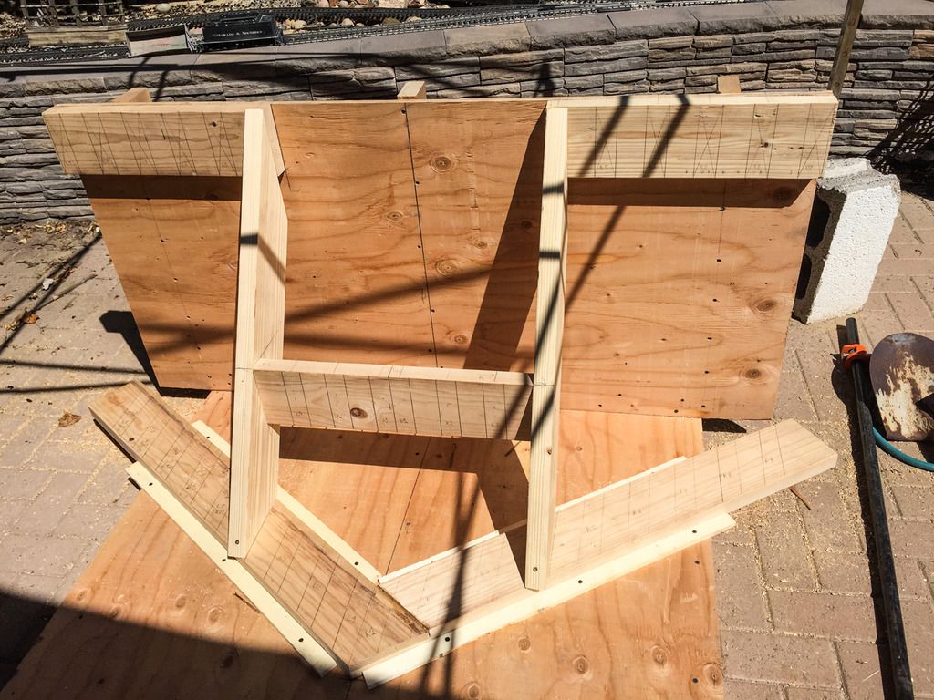
And cut and attached the middle section boards. The center has two boards sandwiched together for added strength. The D&RG used two 1/2 " steel pieces.
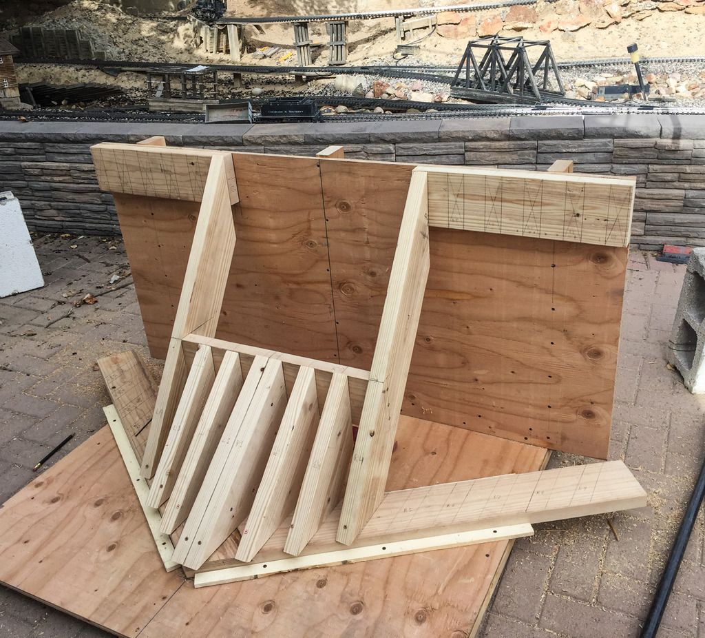
It’s starting to look like the real thing. This project is to large for my workbench and would be to tall to work on, So it’s being built in my back patio.

Had to call a halt today due to RAIN, whooyah. In this drought conditions we always welcome any rain we can get, even if it slows down other projects.

Stay tuned for more.
Got back to work today, and finished up the major construction.
Started by adding the outside boards.

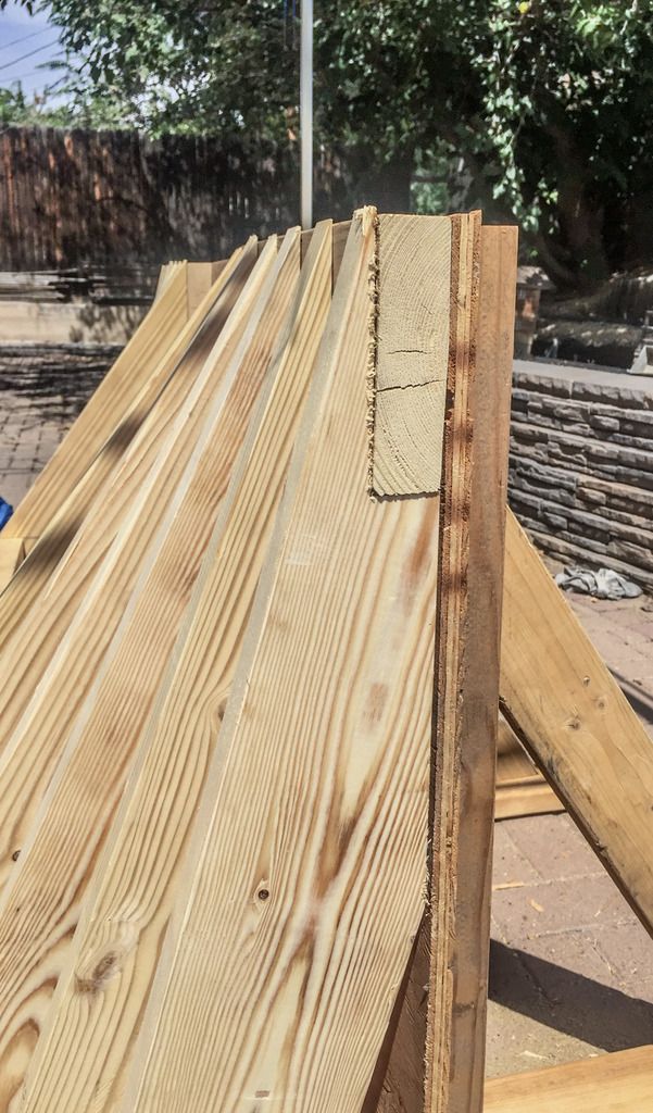
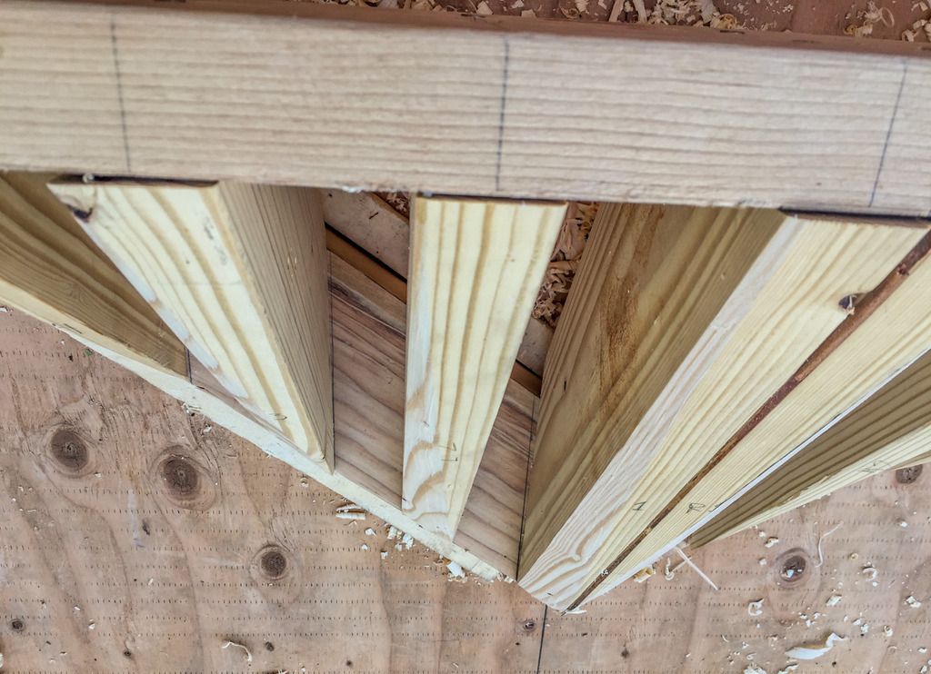
And got the rest filled in. The near vertical boards on the outside ends needed to be notched to fit the top board. Notice how tight of an angle these are you at.

Had to hand cut that sharp of an angle, as the miter saw just wouldn’t cut it.

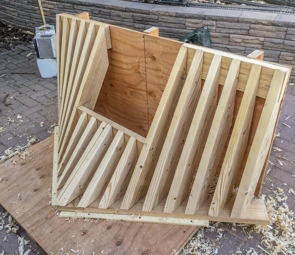
And finally got them all installed.

And the end boards notched to fit the top board.

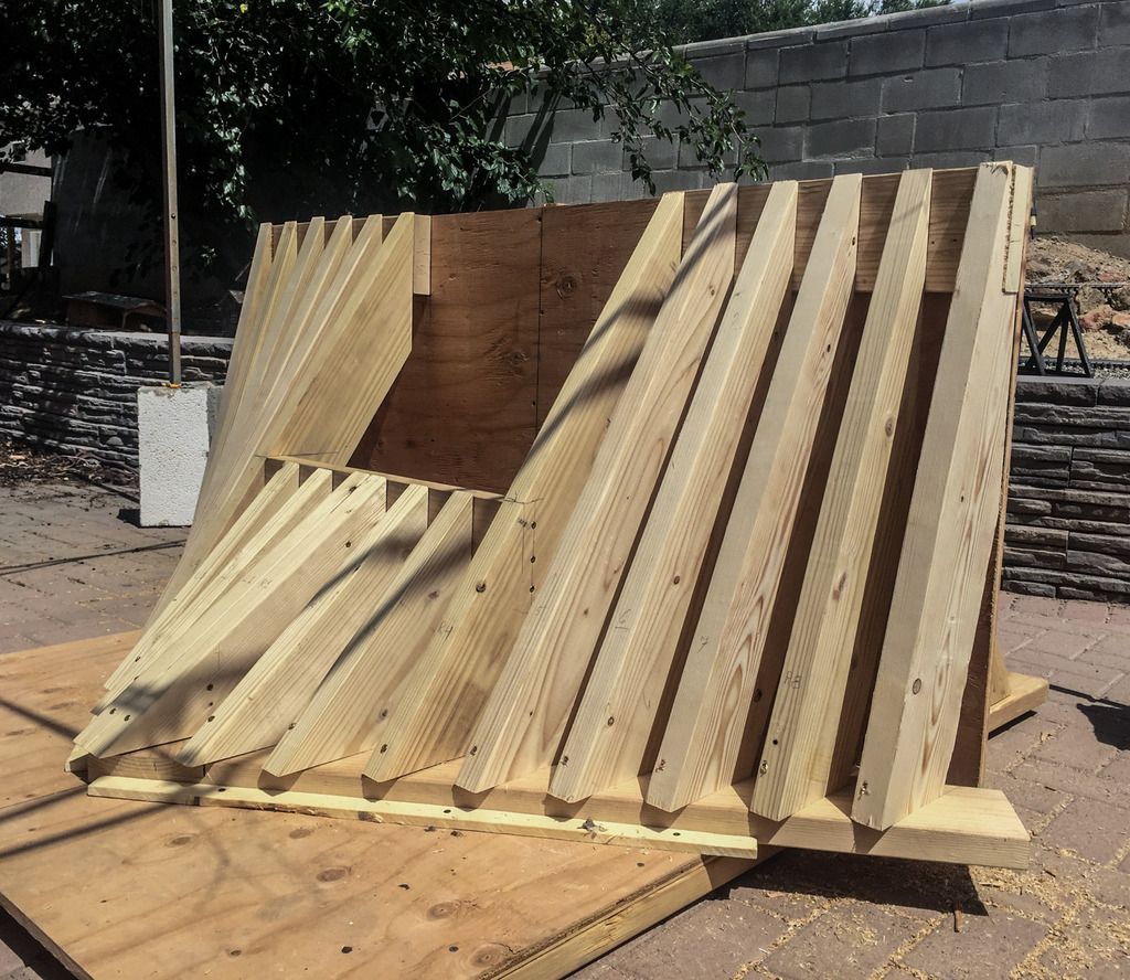
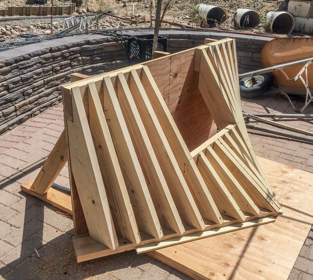
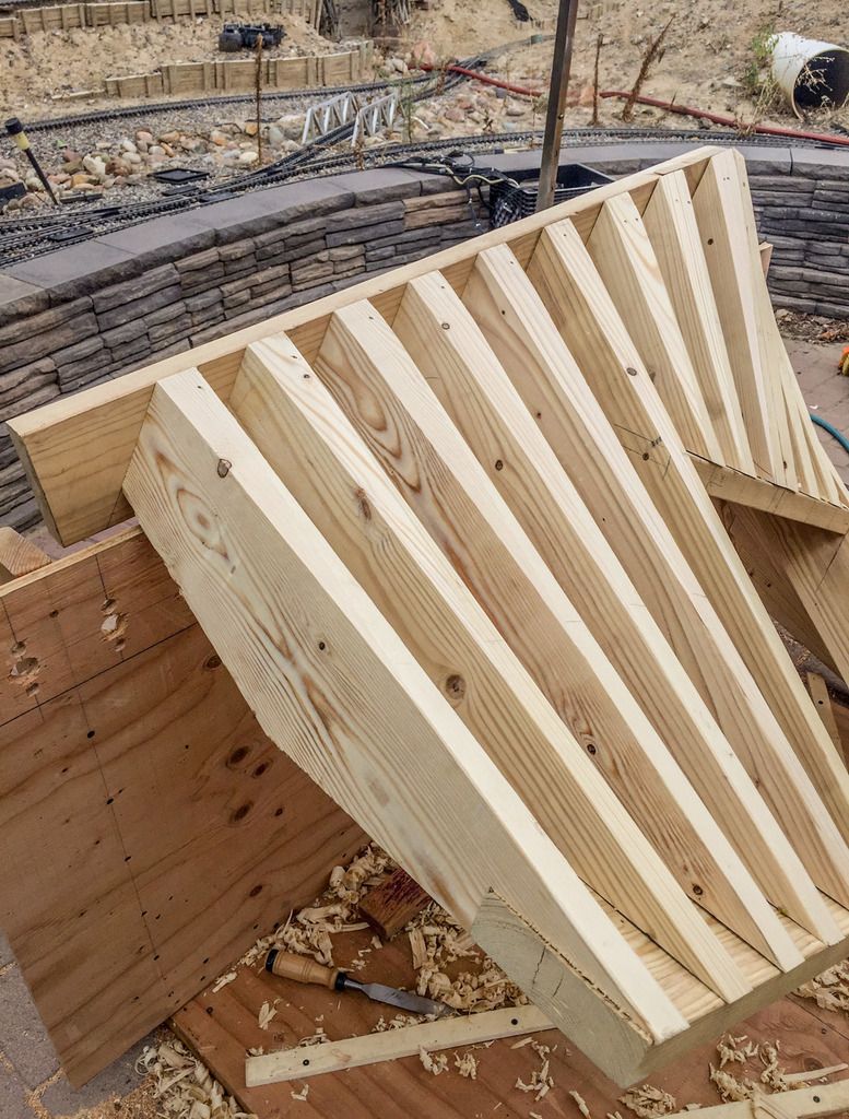
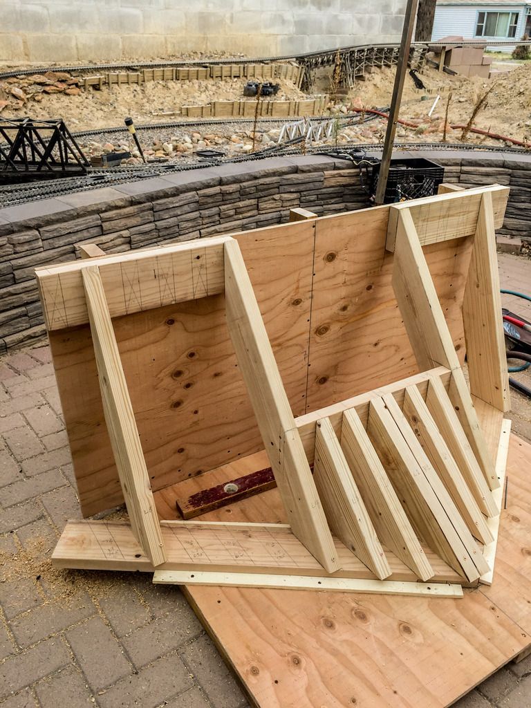
And all assembled. Looks like the real thing.

Next up will be drilling and screwing the vertical pieces to the bottom board. During construction a temporary screw held them in place.
And then planing down the fronts to match the “v” of the bottom board.

Stay tuned.

Dave,

Will it be painted black or stained a darker wood color?

Painted engine black.

Tackled some of the finishing stuff. Started by removing the CC from the jig, and drill and screwing all the vertical boards to the bottom board from the underside, and then removed the temporary screws from the bottom front of each board.

Started to remove the corners of the vertical boards to match the diagonal of the front. doing this gives the vertical boards a funny kind of taper to each board. Started the removal of the big stuff with a chisel and a mallet, and then finished with a hand plane.

Finished up one side, It’s starting to look like the real thing.

Tackeled the other side, and a few hours latter. All Done!!

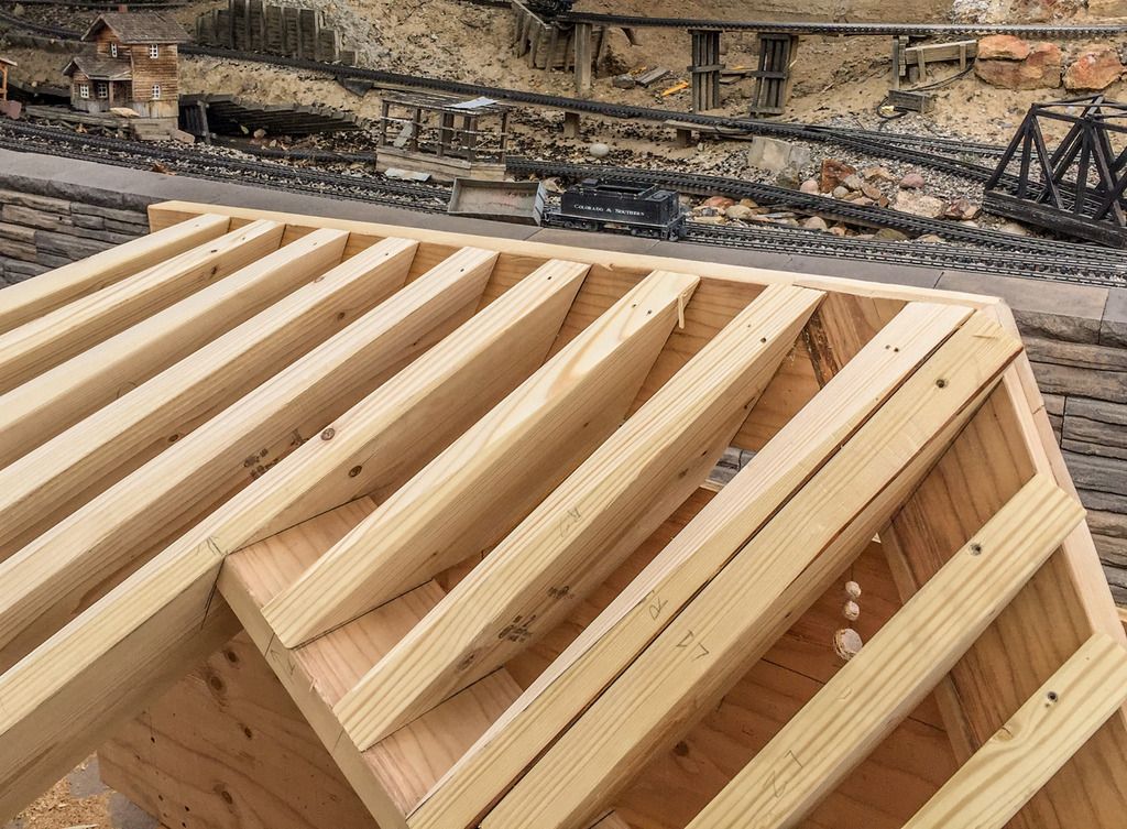
And looking down from the top at the center and middle section.

Looking at the very front.

And the right side.

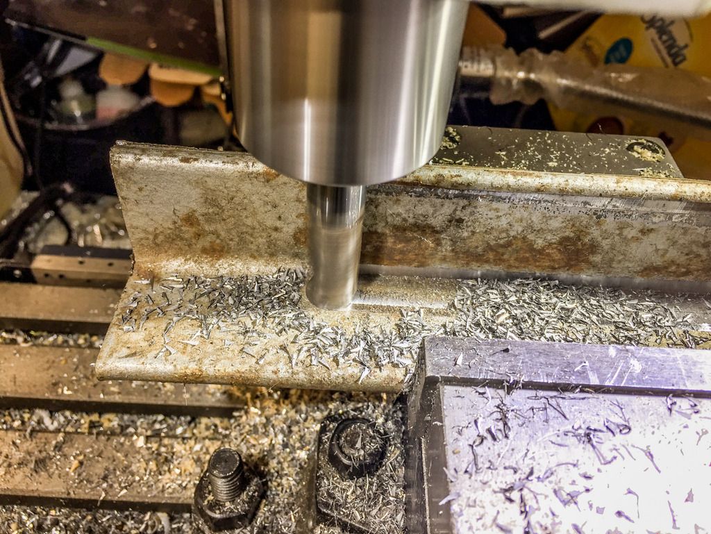
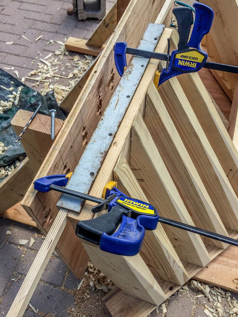
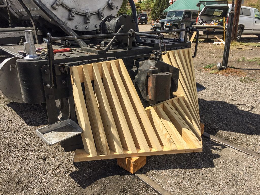
To attach this to the locomotive over the top of the pilot on the 315, we plane on hanging it off a bracket that is attached to the top of the pilot beam. To hang it we will use 1 1/2 ’ x1/4 thick angle iron, attached to the top boards.

I decided that the round fillet on the inside protruded to far, and I milled it out for a closer tolerance fit.

And finally attaching to the top boards with 3" screws, in 5 places on each side.

All done for now. Tomorrow 9/4/18 we take it to Chama for a test fit, and check for interference. Any Day in Chama is a good day.

Stay tuned.

Made the trip to Chama from Farmington NM. ( 2hr drive) with fellow 315 crew member Mike Heuser ,

Test fit the new Cow Catcher to the pilot. Fit like a charm.
]

We did decide to improve on the mounting / attachment to the current pilot. adding some additional steel to better help secure.

Going to work really fine, Looks good, and not overpowering.

This will really give the consist a vintage look for those that will be lucky enough to get to come along on the charter.

Stay tuned.

Pilot looks really good Dave.

It looks better than what was on there! (https://largescalecentral.com/externals/tinymce/plugins/emoticons/img/smiley-wink.gif)

Very fine work indeed! Is it going to be pulling the newly rebuilt coaches?

Dave, you do realize that you did such a good job that this “prop” will be reused many more times in the coming years.

The “New Old Cow Catcher” really does make the engine look “Classic”

Yes the back dating to 425 is to time match the recently restored coach 292, and the newly done RPO.

And yes we do hope that we will get to run as 425 a lot more often.

And “Thank You” for the kind words.

Beautiful work, looks like you’ll need a huge bottle of Floquil’s weathered black!

Nice, I seen the one coach after it was finished, can’t wait to see the entire lineup!

Dave, as before ‘awesome work’; now that I’m disabled I miss the 'ol days at Steamtown-prior to NPS. *about 15-20 years ago had finished the work on #127, 100 year old wooden coach of the Quebec Power & Light made into a ‘display car’ by (2) Canadian volunteers when it was in Bellows Falls Vermont. **that earned me my appointment to traincrew as a Yard Conductor & Trainman. When working on a Saturday, Nelson Blounts son was visiting and came into the car and was impressed by my amateur millwright skills…

That is a very cool project! Have to keep that in mind for the WW&F…the portland forneys had very long pilots when new too. Back in the days of link and pin couplings.

Well D&RGW 315 or 425, or F&CC 3 started life with L&P ( Link & Pin) couplers. Back then on the front of the engines the Pilot ( cow catcher ) was with a much longer point on the front. Since there wasn’t a Knuckle on the front, the engines typically had a "Long Bar " type link that would give clearance when coupled to another car or engine.

When Automatic couplers were required, the long cow catchers went by by, so that cars would fit together, especially engines nose to nose. The D&RG got rid of the wood cow catchers and went to steel in the 20’s, Not all at once, but usually at overhaul times, or when they got damaged. This causes lots of grief to the guys that can’t nail down an exact dates of prototypical changes for a engine class. Now ALL the “K’s” were made with the steel front ends, unless they were changed out for switchman’s platforms.

Dave

That’s very nice work Dave. Really adds a lot of character to the engine!

Great job! Thanks for sharing all the progress pics.

After test fitting the new cow catcher to the pilot, and assuring the clearances and re-designing the attachment hardware, it’s time to get down to final construction.

But first, it had to be disassembled, so this is it as it lays.

I will use Titebond III water proof glue on all joints, 3 " wood screws, and dowels where extra strength is needed. I’ll also add a extra board to fit up against the existing pilot to prevent movement.

Stay tuned.