Large Scale Central

Corrugated Tin Roller

Dave Taylor said:

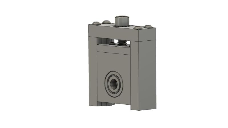
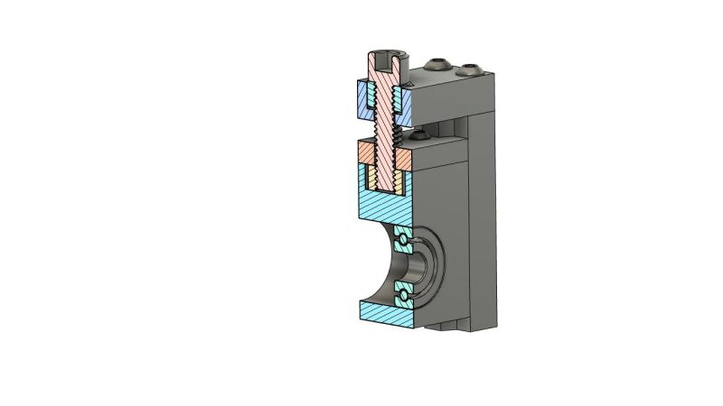
Dan… Not to burst your bubble… But… I don’t see any means to adjust the depth interface between the two rollers… Very important to regulate the depth of the crimp, and the clearances between the rollers for any changes in material thickness, and annealed state…

Details, details (http://www.largescalecentral.com/externals/tinymce/plugins/emoticons/img/smiley-wink.gif)… thanks for pointing that out, Dave. Believe it or not, I had thought about that early on in the design process but chose to fix the distance based on the 0.002 steel shimstock I am using. Probably should (will) make that change once I get the rollers printed. Question, regardless of the method used to adjust the height, there is always the issue of keeping the adjustment roller level because I am assuming, without giving it much thought, that the two ends of one roller will have to adjust independently. So how do you keep them level? Count turns on an adjustment screw? Pre set adjustment heights? Any suggestion?

EDIT: To ask one more question.

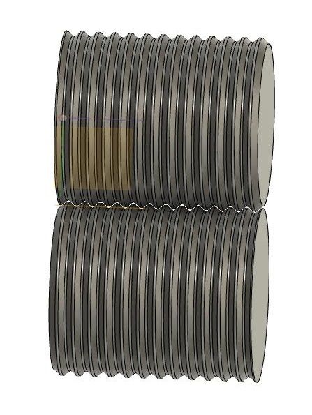
Dave, I considered trying a roller orientation as shown below, but I don’t think there will be enough friction to pull the stock through and its not stiff enough to push. Any thoughts?

The Taylor Tim factory uses the duel grooved male and female roller system like your last pic. The harder the metal, the more difficult it is to get the “grab” on the rollers. Softer, “annealed” metal will “stretch” as it passes thru the rollers.

Harder, metal will be stretched to the cracking or tearing point. In the real manufacturing world, corrugations are rolled one grove at a time, allowing the metal to form without a great deal of stress or stretching, more of a fold, then a stretch. The metal passes thru a series of forming dies from the start to finish.

Dave

Thanks for the insight, Dave. I prefer the grooved male - female rollers to the ones I presented above. Much less printing. I was just worried about there being enough friction to pull the material through.

Per your recommendation, here is the first pass at a vertical adjustment mechanism. It still needs to be incorporated into the model but that’s the easy part … I hope.

Yeah, I know, I should be working on my MIK project, but all I like other than the painting is installing the roof trusses and mounting to the deck and I’m working on that. all the printing is done … FINALLY.

You may run into tearing on the standing seam if the metal can’t gather material from the sides for the height. Might require 2 passes one to form the seam and the second to form the bends to flat determining the height of said seam.

Bearing drawing, No threads on the lower half of the adjusting screw, It needs a ring to fit in a groove on the shoe for up and down motion controlled by upper threads. No?

John Caughey said:

You may run into tearing on the standing seam if the metal can’t gather material from the sides for the height. Might require 2 passes one to form the seam and the second to form the bends to flat determining the height of said seam.

Bearing drawing, No threads on the lower half of the adjusting screw, It needs a ring to fit in a groove on the shoe for up and down motion controlled by upper threads. No?

John, it appears that way but in reality that lower nut is captured but can rotate and I will epoxy the nut onto the adjustment screw so the adjustment screw will travel with the rollers. I could simply print a ring as you say with threads and epoxy that to the screw. End the end either way will work.

I see…(https://www.largescalecentral.com/externals/tinymce/plugins/emoticons/img/smiley-wink.gif)

I’d suggest drilling and pinning the nut to the shaft, just because of the stresses.

Neat project. I have one of the Fiskar crimpers right now with a modified holder, but I really want to make one using spur gear stock like this. https://sdp-si.com/products/gears/Spur-Gear-Stock-Metric.php

That’s more or less what I am attempting to do, Bob, just with 3D printing. Based on Dave’s input, I think I am going to try the male-female style rollers first, though.

Here is the height adjustment incorporated into a stand. This gives you an adjustment of 4mm down and 10mm up. Way more than needed. The initial gap as it sits now would be 0.3mm.

Dan Hilyer said:

Here is the height adjustment incorporated into a stand. This gives you an adjustment of 4mm down and 10mm up. Way more than needed. The initial gap as it sits now would be 0.3mm.

Great project, Dan! I’m loving how you’re 3d printing a fairly complex tool – which maybe has no equal on the market? How fun!

Your screw arrangement also caught my eye; you answered John’s points, but here’s a couple more, if you don’t mind.

If I’m understanding the device properly, you’re forcing the upper bearing down toward the lower; and that position must overcome the stiffness of the metal sheet. If so, I expect the upper nut to push upward away from and out of its its pocket. To prevent that, you could put the nut pocket on the underside of the removable upper bar, and perhaps thicken that bar to handle all that upward force.

Second thought, for your lower nut, since its load surface is on its bottom side, you might want to make room for a washer or something for it to press against. That would spread the load out, and prevent a hex-shape dimple in the plastic (which could fight with the finer adjustments).

For locking the lower nut in place, if drilling as John suggested is difficult, you could (if you have the vertical height) plan for a double jam nut, which can be far more secure than nylocks or Loctite. Alternatively, you could save space and turn your socket head screw upside-down, and use a jam nut against a threaded knob on the top side. That way you’d see if something was loose, and be sure all was firm down below.

Finally, since you’re screwing into plastic (or maybe you’re using metal inserts?), and since those upper for screws will see your upward force, I’d make your upper bar as wide as the main mount, and center the screws. That way, if you later need to install inserts (or larger screws, if those holes give way), you’ll have plenty of space to work with.

Just thoughts, take them for what they might be worth… My main point remains the same though, that this is such a cool project, and I’m really looking forward to your cranking out some sheets!

All good observations, Cliff. I had intended to simply epoxy that top nut in place, but your suggestion makes more sense but I’ll still epoxy it on the underside. That change has already been made in the model. The lower nut will work as is since there will be few adjustments once its set the first time but it has been bothering me. I’ve thought about epoxying a bearing on the end of the screw and adding a lip to catch the outer race of the bearing and let friction lock it in place. I’ll have to think about that one some more. The upper four screws are threaded into the plastic and extend a little over 10mm down into the main stand. I’m not sure there’ll be enough upward force to push the screws out of the plastic, but we will see. I could be wrong, I have been before … I think … maybe not (http://www.largescalecentral.com/externals/tinymce/plugins/emoticons/img/smiley-wink.gif)

I appreciate all the observations given thus far. Its always good to have multiple sets of eyes on a project such as this. If I can get this thing to work, I will gladly share the print files or even the design files for anyone who wants to make one of their own.

Dan… Taylor Tin’s roller press is of the same basic design. This is version -3… Having learned that the first two versions would not work with " annealed Alum. cans",( soda or other beverage). or annealed Alum flashing from the big box stores, or of alum. duct work. raw and annealed.

As you can see… your design is much higher refined then my machine. Yours, with direct gear drive just may well work where mine design failed.

My top roller is a “Floating” interference design. where the upper limit is restrained from travel, and sets the groove depth.

EDIT: also shim stock ( by it’s very nature) is way to hard, as the kilm i used to anneal would not reach high enough temp to be effective to remove the hardness. And soft brass would feed, but was prohibitory on the price point.

One way to enhance the design that Dave and Dan have proposed is to add another set of plain pinch rollers (rubber coated?)to feed the stock into the grooved forming rollers. am a little concerned on how this will all work in 3d Printed plastic, as the material will wink when a load is applied. sometimes real metal or alum is called for.

Al P.

Dan are you at all concerned with the plastic flexing and not giving repeatable results, and will the plastic rollers wear out quickly?

Dan… what metal, or stock do you plan on using to make the panels from…?

Dave Taylor said:

Dan… what metal, or stock do you plan on using to make the panels from…?

I’ve been using 0.002" steel shim stock with the paper crimper with success. I also have 0.003 aluminum and 0.002 brass I am going to try. I’ve discovered through testing that the roller profile must be a little more aggressive than I originally thought.

Pete Lassen said:

Dan are you at all concerned with the plastic flexing and not giving repeatable results, and will the plastic rollers wear out quickly?

Pete, I don’t think the PETG filament I am using will wear out or flex. The paper crimper I have been using is all plastic including the rollers and I have seen no issues with it other than I can’t control the profile. Should the rollers wear out prematurely, I can print new ones or make them out of a different filament such as carbon fiber or even some of the newer filaments that have various forms of metal in them. I have used the carbon fiber before and it works well, but I’ve never used the metal infused filaments so there certainly would be a learning curve. This whole thing may be an experiment in what not to do but at least we’ll all know in the end.

Dan - chipping in here. I was looking to do something very similar, but then I found a press tool on eBay in the G Scale section. You’ve probably seen it. It makes sections about 4" x 7", which would be on the order of 96" x 168" in full scale if you were modeling in 1/24. This is larger than most real-life sheets would be, so I think the smaller pieces actually seem more realistic. He designed this for 36 gauge aluminum, but actually, using a cut-up pop can works pretty well. Search on “Make your own G or O scale roofing” and you can see what it looks like. Added bonus is the sheets come out flat!

Trent

Trent, I’ve not seen that particular press. it looks like it produces a form of standing seam roofing. I’ve consider something similar, kind of a hybrid between the press and the rollers I am attempting to use. Make a bed similar to what is shown on ebay, but instead of using a press, have a roller with a mating profile as the bed and let the roller move on a rack and pinion mechanism along the bed. The press is probably much easier sinc its less moving parts, but it would take a long time to make a large quantity of roofing. Thanks for the information. If this experiment fails, I may look at going the press route.

Trent said:

I was looking to do something very similar, but then I found a press tool on eBay in the G Scale section. You’ve probably seen it. It makes sections about 4" x 7", which would be on the order of 96" x 168" in full scale if you were modeling in 1/24.

I’m wondering how this works? The seller doesn’t specify. The plates look like they are clad in oak so I imagine you could just pound it with a mallet but there are the screw holes so I’m thinking you use bolts and ratchet it down. The holes are missing from one side probably to facilitate loading/unloading.

Dan, I believe this roofing is just corrugated “sinewave” type. Although it does look more “fanfold” than most. Standing seam has the edges raised high and the panels lock into each other rather than overlap. Just so happens I’m looking at putting a metal roof on my home now. Also, what crimper do you have? The only one I’ve seen is the one I have made by Fiskers and has metal rollers.

Dan Gilchrist said:

Trent said:

I was looking to do something very similar, but then I found a press tool on eBay in the G Scale section. You’ve probably seen it. It makes sections about 4" x 7", which would be on the order of 96" x 168" in full scale if you were modeling in 1/24.

I’m wondering how this works? The seller doesn’t specify. The plates look like they are clad in oak so I imagine you could just pound it with a mallet but there are the screw holes so I’m thinking you use bolts and ratchet it down. The holes are missing from one side probably to facilitate loading/unloading.

Dan, I believe this roofing is just corrugated “sinewave” type. Although it does look more “fanfold” than most. Standing seam has the edges raised high and the panels lock into each other rather than overlap. Just so happens I’m looking at putting a metal roof on my home now. Also, what crimper do you have? The only one I’ve seen is the one I have made by Fiskers and has metal rollers.

Dan, I have one made by Marvy and it definitely has plastic or some type of resin rollers. To lite for metal and I sliced a piece off with a hobby knife just to be sure.