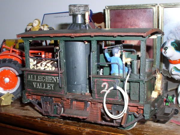
My ozark order came in yesterday. My plan was to do some more work on it yesterday but thanks to the guy who decided to climb up a cliff with no rope and get stuck. I ended up getting called out for a rescue GRRRR. Hopefully today with the rain I can get a lot more done. Im still trying to figure out what to use for the water tak. Im going with the round tank and everything I find is either too big or to small.
what about a Spam can, by cutting about 1/3 off the bottom?
tuna can? plastic pipe cap? piece of wood cut with a scroll saw or circle cutter? large printer tape roll center? dollar store tumbler cut off?
I have a pipe cap but I can add a tuna can to give it a little more height. Ill have to try that one. Spam can might work as well. I will have to see what I looks best. Thanks guys. Guess whats for lunch? Not spam (I do have a gormet coffee cans in the same shape).
What diameter are you looking for?
Bruce Chandler said:I wasnt looking for anything too specific in diameter. I had a 2 inch pipe cap that was perfect but I needed something that was another inch higher. I ended up wraping styrene around the pipe. It worked perfect because were the seems join I put rivets along the seem and it gave me the height I was looking for. I solved that problem. I also started adding the details: pipe off the sand dome, the fire box and the other piping in the front. Next challenge I need to focus on building the engine. Sorry no pictures yet. weather outside s-u-c-k-s and inddor pictures never come out clear on my camera.
What diameter are you looking for?
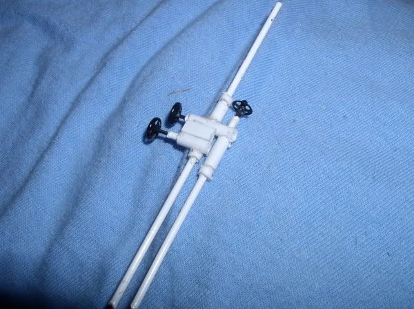
Might wanna shorten that injector line. Spraying water in the smokebox will do ya no good! OTOH If it’s supposed to be the blower, get rid of the check valve.
Thanks Mik. I was not sure how that was suppose to go.
I moved them back and took off the one piece. Now it is set up like my Big John.
Injector lines dump in close to the front tubesheet just like on any other locomotive boiler. Lots of usable info on piping in general here… http://archive.mylargescale.com/articles/masterclass/mc1/mc1-06/const/const01.asp scratchbuilt simplified Nathan inspirator (injector)
(http://i397.photobucket.com/albums/pp52/steamnut1917/P1310001.jpg)
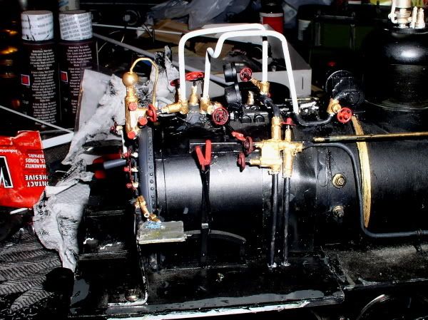
As to WHERE all the crap goes; mount one injector and feedwater line on each side of the boiler. There should be a shut off valve close to where each steamline comes out of the boiler (side of vertical part of the T, near the top). You can cheat and just run the overflow and cold water lines straight down through the floor and end them there. Installed injector on my #5 to give you a rough idea
(http://i397.photobucket.com/albums/pp52/steamnut1917/P2010001_01.jpg)
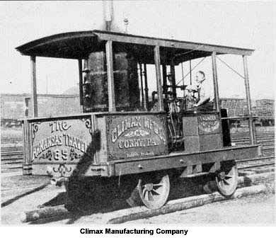
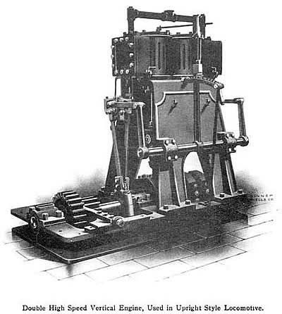
On TOP if the vertical boiler section should be a large tee with one pipe going straight up and the other pointing backward. Early style layout would have the safety on the vertical pipe, later style the whistle or capped. Another pipe comes off the top of the vertical section for either the whistle or safety. On the horizontal run from the above mentioned tee you’d have a large main stop globe valve close to the boiler. Then the steamline to the engine. The steamline should run straight rearward then make a 90deg bend straight down to the engine. About halfway down this vertical run between the bend and the the engine is where they stuck the displacement lubricator. Then the throttle would be mounted at the bottom, just above another tee with each leg of the tee running to the engine’s steamchests. Look at the factory engine drawings and pics already provided if you get stuck. The johnson bar and quadrant in that drawing is for the reverser. The throttle lever was usually mounted horizontal or diagonal to be easier to use. You can see the steam line and throttle in this pic. Climax left the controls the same when they went to the t-boiler. It also looks like there was a pressure gauge mounted above the throttle where the engineer could easily read it.
(http://www.climaxlocomotives.com/confirmed/img/sn65.jpg)
The other side of the engine will look something like this… except the exhaust will be routed downward, then forward to the smokebox.
(http://i397.photobucket.com/albums/pp52/steamnut1917/P3260003.jpg)
The other thing you may wish to model is an ejector – used to pick up water from streams or even horse troughs. these can be mounted either vertical or horizontal, but are usually situated at the top edge of the water tank.
(http://i397.photobucket.com/albums/pp52/steamnut1917/P3300001.jpg)
Hope it was understandable…
Thanks Mik. I was never too sure where the pipes went or what they were for. That does help, I think I got a better understanding just going to take time for me to get it. The more I do it the better I will understand. Can I get away with the shut off valve being up front like my HLW Big John or is that wrong and put the turn off by the boiler? Actually looking at the big john I might have duplicated that system? Ok I just looked on that article. I never knew about that article. That really points everything out. That answered my questions. I am Ok with the HLW set up just have to add turn offs and the cold/hot water pipes down from the boiler/firebox area. In all the climax pictures I see the line coming out of the boiler going back into the T part. Did the Class A have the turnoffsw there? Thanks again.
(http://i53.tinypic.com/2dkjn7.jpg)
I was going to use Timmyd’s climax build as a reference for the piping on the engine to the boiler. Seems very basic http://timothydehan.com/redmondcreekrr/ClassAClimax2.htm.
the shut off in the front is the feedwater line… some had it, some didn’t.
Timmy done good, except for having the donkey pump feed cold water directly over the crown sheet… in the real world that’s asking for trouble (leaks due to thermal stress) BTW I HATE the Ozark engine… if you’re going to use it after all this, shoot me now. or please please please modify it so it at least looks right!
Mik said:
the shut off in the front is the feedwater line... some had it, some didn't.Timmy done good, except for having the donkey pump feed cold water directly over the crown sheet… in the real world that’s asking for trouble (leaks due to thermal stress) BTW I HATE the Ozark engine… if you’re going to use it after all this, shoot me now. or please please please modify it so it at least looks right!
LOL Im going to attempt to make the engine but I was going to make it similar to the ozark. ( I didnt even know Ozark made that one) What should I do differently? I did get the pump from ozarks to put along side the engine like timmyd has. hanks again Mik you have been a great help with the piping.
All that plumbing and I still don’t see a toilet or sink yet?

David Russell said:
All that plumbing and I still don’t see a toilet or sink yet?
A friend of mine modeled the fireman wizzing off the side on his On3 layout. Does that count? BTW, most folks never notice him. OK, why I hate the Ozark thing. They had a chance to do it right, but just didn’t. It looks more like a Westinghouse or Fairbanks-Morse diesel engine for driving a dynamo than ANY ‘marine steam engine’ that I’ve ever seen. Ozark engine (Timmy D’s photos)
(http://timothydehan.com/redmondcreekrr/images/ClassAClimax_Ozark/IMG_1958_800x600.JPG)
(http://timothydehan.com/redmondcreekrr/images/ClassAClimax_Ozark/IMG_2529_640x480.JPG)
REAL engine
(http://i592.photobucket.com/albums/tt7/tigerlillie06/His%20Stuff/03.jpg)
First the look at the reverse lever location. Where Ozark put it simply makes no sense… other than it used a part already in their inventory. — The crankshaft runs there! Next, look at the base and cylinders… more like a marine diesel than a steam engine. The base should be MUCH taller, the cylinders shorter. There’s just no room for crossheads and guides in it at all designed like that. Then take a real good look at the steam chests. Just like the cylinders, HALF that length would be about right. There is also noplace to PUT the Stephenson’s reverse links and rods if you DID decide to model it… Unless you set the cylinders ridiculously far apart. Yes, yes, I know. They specifically claim it is a ‘generic’ marine type engine, not a Climax engine model, but IMO that’s a bit disingenuous - considering the call the MODEL a ‘Climax engine’. I’m pretty sure Climax had some patents on their design. I guess to many folks it won’t matter, but even with all the stuff I fudge, the obvious ‘who gives a shit’ fudging on this annoys the crap outta me… If only because it should be RIGHT for that asking price. Generally, I love Ozark’s stuff, but this one just bugs me. http://www.ozarkminiatures.com/scripts/prodView.asp?idproduct=1145
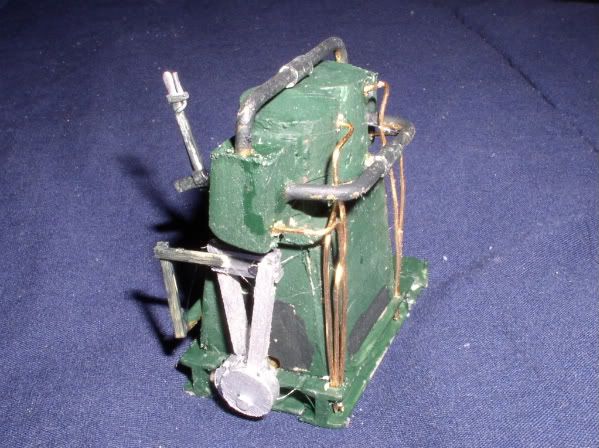
And before somebody says 'Let’s see you do better!" I cobbled mine together out of wood scraps, styrene and wire… No, it doesn’t have the nice finish and all the pretty nut castings, but the proportions are there… and so is the reverse gear.
(http://i397.photobucket.com/albums/pp52/steamnut1917/P3250005.jpg)
Mik said:
David Russell said:
All that plumbing and I still don’t see a toilet or sink yet?A friend of mine modeled the fireman wizzing off the side on his On3 layout. Does that count? BTW, most folks never notice him. OK, why I hate the Ozark thing. They had a chance to do it right, but just didn’t. It looks more like a Westinghouse or Fairbanks-Morse diesel engine for driving a dynamo than ANY ‘marine steam engine’ that I’ve ever seen. Ozark engine
(http://timothydehan.com/redmondcreekrr/images/ClassAClimax_Ozark/IMG_1958_800x600.JPG)
(http://timothydehan.com/redmondcreekrr/images/ClassAClimax_Ozark/IMG_2529_640x480.JPG)
REAL engine
(http://i592.photobucket.com/albums/tt7/tigerlillie06/His%20Stuff/03.jpg)
First the look at the reverse lever location. Where Ozark put it simply makes no sense… other than it used a part already in their inventory. — The crankshaft runs there! Next, look at the base and cylinders… more like a marine diesel than a steam engine. The base should be MUCH taller, the cylinders shorter. There’s just no room for crossheads and guides in it at all designed like that. Then take a real good look at the steam chests. Just like the cylinders, HALF that length would be about right. There is also noplace to PUT the Stephenson’s reverse links and rods if you DID decide to model it… Unless you set the cylinders ridiculously far apart. Yes, yes, I know. They specifically claim it is a ‘generic’ marine type engine, not a Climax engine model, but IMO that’s a bit disingenuous - considering the call the MODEL a ‘Climax engine’. I’m pretty sure Climax had some patents on their design. I guess to many folks it won’t matter, but even with all the stuff I fudge, the obvious ‘who gives a shit’ fudging on this annoys the crap outta me… If only because it should be RIGHT for that asking price. Generally, I love Ozark’s stuff, but this one just bugs me. http://www.ozarkminiatures.com/scripts/prodView.asp?idproduct=1145
Hey Mik, those are my pictures. And, while you may not like the Ozark engine, for one who is not a rivet counter I like it alot and think my model turned out great! It also runs great!
I’m kinda sad I didnt keep my Class A building log pic online, but your doing A-OK Shawn
Mik, Ozark might have ment that lever to be the Hi-to-Low gearing shift lever, though it should be re-oriented 90degrees to run parallel to the driveshaft.
Timmy, as I said, you did a really good job. And if I offended you by using the pics that Shawn linked to to illustrate why that engine is wrong in their kit, I’m sorry. It was not my intent. The fact that everything else looks great, and the thing ‘runs great’ is a good thing.
I don’t ‘count rivets’ either, but it has to look at least plausible to me. You had the kit, you worked with what you had. Shawn is going to scratchbuild his. So why should I NOT advise him work from a correct catalog cut rather than from an incorrect model? I would suggest alternatives if someone planned to upscale a Lifelike Teakettle, too.
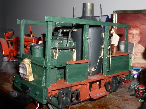
Here is my rendition of a Class A Climax marine engine. Sorry for the poor photo.
(http://freightsheds.largescalecentral.com/users/jlcop/classa.jpg)
John