Large Scale Central

Build Log: The CVSRy's replica log cars

I use wood screws or sheetmetal screws all the time to hold on trucks. Even on factory cars where the kingpin has broken off, split or stripped.

The easiest “assembly jig” is to simply draw outlines on newsprint or butcher paper if you only have a few to do

I got a back-channel message from Ken that has me re-thinking the truck / bunk locations. When I first drew the car up, I thought the trucks were pushed too close to center, so I moved them way out. Then after scaling Mik’s plan, I moved them back in some, but not as far as the 1:1 drawing.

Before I get much further into the build I’m going to mount couplers and trucks on two of my jig-test frames and make sure they will track through my mainline curves. Depending on how that works, I may move them closer to the ends again.

Mine are about 1-3/4" in from the ends. I was working solely from Cale’s pix and just put them where the looked ‘right’

(http://i397.photobucket.com/albums/pp52/steamnut1917/P2140001.jpg)

(http://i397.photobucket.com/albums/pp52/steamnut1917/P2150002.jpg)

And, if you decide to do the vertical posts. Jewelry pins from MalWart’s craft department, Ozark’s finer chain, plastruct and small nails make acceptable looking hardware.

(http://i397.photobucket.com/albums/pp52/steamnut1917/P2180002.jpg)

Mine are about 2" back from the end, and mine all have the L & P couplers except for the 2 cars at each end. L&P’s aren’t as forgiving as the knuckle couplers. The 2 end cars also have the bigger wheelsets on them so the Kadee’s line up better with the Shay.

OK - My drawing has the trucks/bunks 3.5" back from the end beam. I can see now that that may be an operational problem :slight_smile:

Free advice is worth at least what you paid for it :wink:

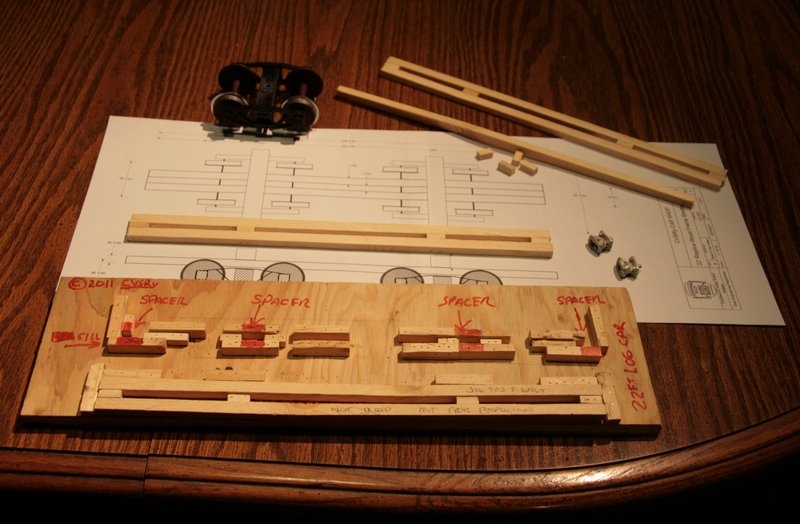
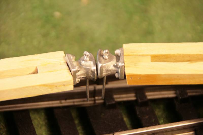
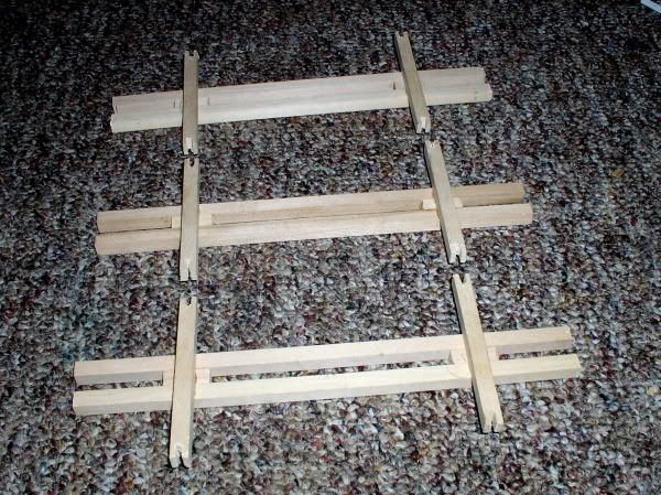
Time for a status report. I finally finished the nail-up jig and built a few test frames. Here’s an overall view of the frame jig, a full-size set of plans and a few parts and assembled frames…

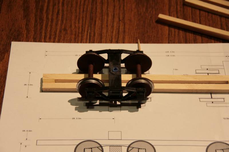
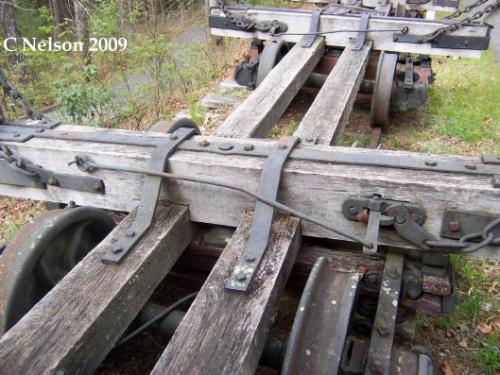
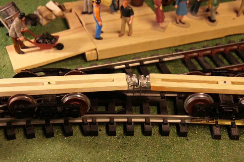
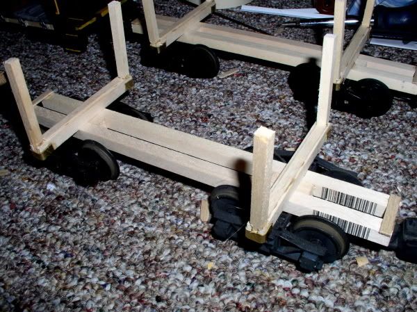
Here’s a truck and a frame laid out on the full-sze plan for comparison…

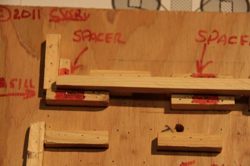
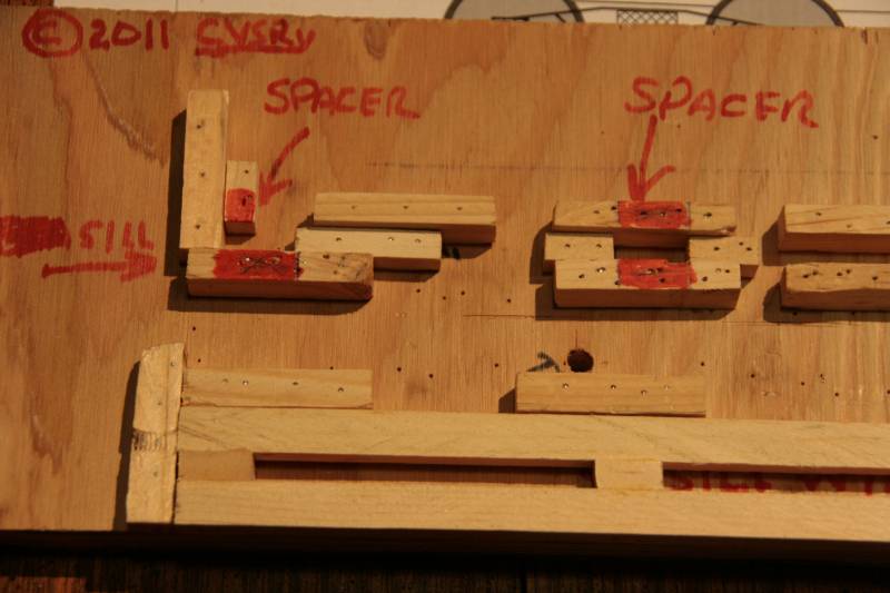
The jig is used to position the spacers on the sill…

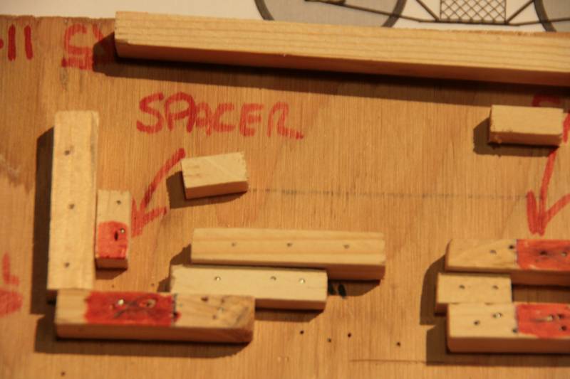
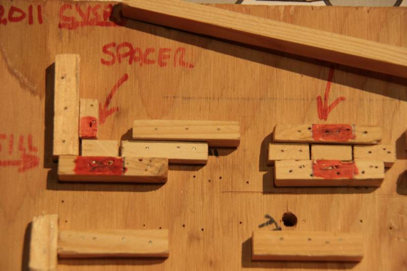
Some glue is dabbed on the spacers, then a sill is joined to the spacers in the jig…

A few air driven pins are used to hold the glue joint on each spacer, then the sub-assembly is removed from the jig, a few more dabs of glue are added to the other side of the spacers before moving it to the next area where the second sill is added and pinned in place…

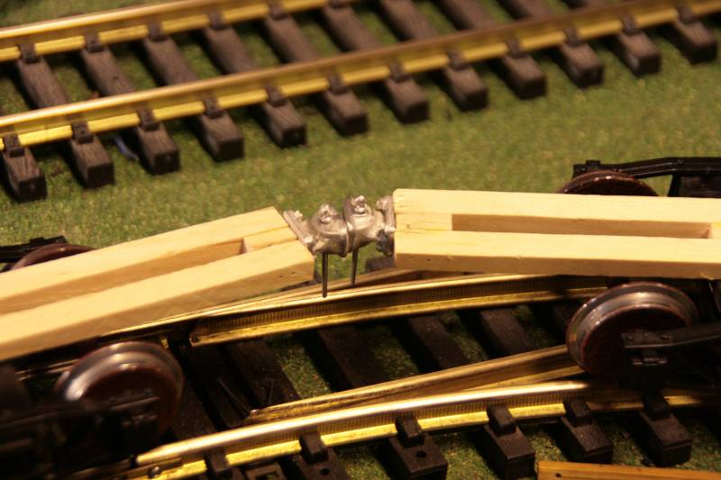
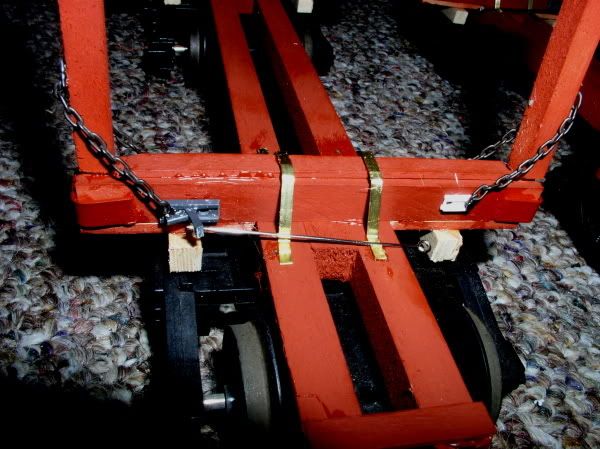
Once I determine my pivot point or the trucks I’ll build a jig to assemble the bunks. I wish I had a dado blade because I’d really like to drop the bunks over the sills like Cale’s prototype…

just set your table saw blade to height, mark your area and nibble away at the opening. Use your fence for a stop and keep a critical eye on your first cut and you’ll be fine.

Edit to add looking good so far. Those jigs do help

A #115 milling cutter in a Dremel works pretty well if you have a steady hand. - or are really stubborn like me :wink:
http://cgi.ebay.com/NEW-DREMEL-115-HSS-HIGH-SPEED-STEEL-CUTTER-/120680054185?pt=LH_DefaultDomain_0&hash=item1c19177da9

Jon,

Wouldn’t a good starting point for location of bolster in relation to the coupler is to look at the old Delton rolling stock? If it worked on one car, wouldn’t the same work on another car?

Ric Golding said:
Jon,

Wouldn’t a good starting point for location of bolster in relation to the coupler is to look at the old Delton rolling stock? If it worked on one car, wouldn’t the same work on another car?


Not quite. Body mounted Link & Pin Vs truck mounted knuckles. The knuckles give a bit from side to side (more so than Lincoln pins) and then the truck mounted coupler give a lot of swing.

In my main line curves It shouldn’t be too bad, but these guys got me worried so I’m going to test before building a bunch of car frames :smiley:

Dave Marconi said:
just set your table saw blade to height
Put a new blade on that saw...I believe the last time you used it you were cuttin' up rock! Nice jig! ;)
Jon Radder said:
In my main line curves It shouldn't be too bad, but these guys got me worried so I'm going to test before building a bunch of car frames :D
You will probably be fine....if I can get 3' long cars on a 4.5 radius then you can certainly do what your doing.
David Russell said:
Dave Marconi said:
just set your table saw blade to height
Put a new blade on that saw...I believe the last time you used it you were cuttin' up rock! Nice jig! ;)
I forgot that story :) :)

Doesn’t granite sharpen the blade ?

I ran the coupler / tracking tests today with two pre-production frames. No problem at all through my tightest mainline curves and Ariosto “Wide” switches…

They will even get through a single R1 switch (barely)…

But not without lifting a pair of wheels off the track…

They did not derail…

No such luck in an R1 S curve, but I never expected them to be able to do that. None of my other 1:20 cars will even track through R1, so I’m ahead of the game with this design. Now on to production.

cool!

Jon,

Would possibly using a longer ‘dogbone’ shaped link make the cut? Or is the issue with wheel clearance on the main spine?

Bob C.

Hi Jon,

From your photos it looks to me that if you move the trucks out towards the end of the car it would solve your problem. Check some of your other rolling stock as to how far the trucks are mounted from the end of the car, on cars that don’t have the problem the log cars do. Hope this helps.

chuck

Bob - That may work - but again - I don’t expect or need these to get through R1 curves or switches. Check - See above :slight_smile: 
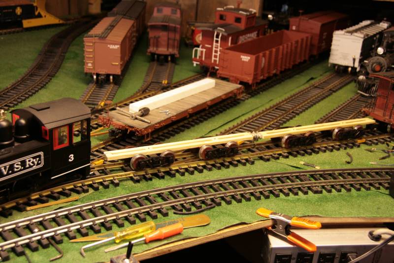
The design passed the main-line test, so I am fine with it as-is. I only tried the yard R1 siding to see if it would go in at all. For my 1:20 stock I have sidings that use “wide” switches. The third and fourth track in in this photo…