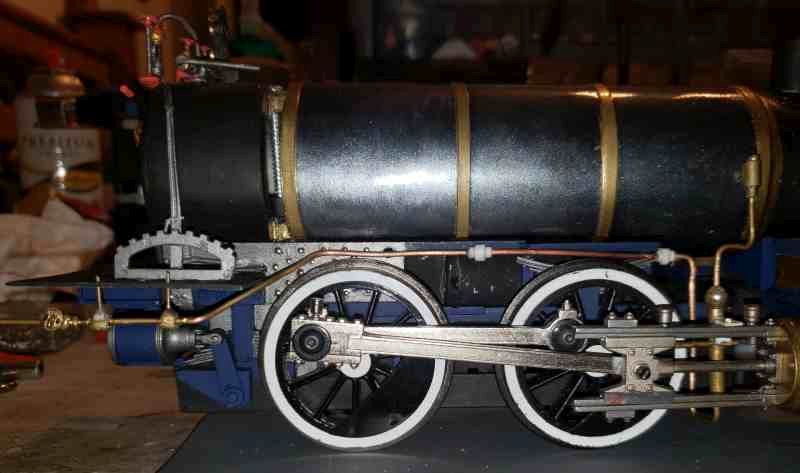
Okay so I am asking this here because I want as many people who might know to see it. I am asking as much for modeling my current loco as I am just curios about the evolution of feeding water into a boiler. I am going to use my prototype picture for reference.
 Picture from Virginia and Truckee.com
So I want to model an early locomotive. And I asked earlier about an “injector” that was mounted on the cross head. I was informed that it was not an injector but a pump driven by some connection to the cross head. On the picture above it is the gold thing between the drivers. One thing I have wondered about this drawing is the “thing” between the domes. When looking for close up pictures of various crosshead feedwater pumps so i could model it I came across this picture and several like it
 picture found here Phase 3 project
So this thing is a feed water pump also. I am assuming it is either acting as the primary feed or as a back up to the crosshead pump. But I am intrigued and may model this instead of a crosshead mounted one. Can someone explaing to me roughly what this thing does and how it works. I assume, unlike the crosshead pump which is using the back and forth motion of the cross head to drive a piston pump, this one appears to be steam powered. It looks to me as if it is using steam to drive the pump. Is this the case? And if so how would it be plumbed. Again I assume you would have a feed line from the tender through the pump into the boiler with a check valve. And that there is a steam line from the turret of ??? that delivers steam to the pump to drive the piston and then that steam could either vent to atmosphere like a dynamo or dump into the smoke box like a air pump.
Ideas thoughts education. I would be interested to know the history of feed water pumps prior to the days of lifting injectors.


