Large Scale Central

7.5 inch Gauge Number 5 Turnout Build

That looks like a much more pleasant way to work on rail than if you were working on the real MoPac/UP here today, below freezing, visible ice on trees and power lines, and gusts over 20mph.

The sacrificial boards are probably something my brain wouldn’t have intellectually thought of beforehand but when setting up the work it would have looked at it and gone, “Ya know what, …”

Forrest Scott Wood said:

That looks like a much more pleasant way to work on rail than if you were working on the real MoPac/UP here today, below freezing, visible ice on trees and power lines, and gusts over 20mph.

The sacrificial boards are probably something my brain wouldn’t have intellectually thought of beforehand but when setting up the work it would have looked at it and gone, “Ya know what, …”

Weather has been great here. Winter is long gone :). Mid-eighties and high seventies past couple of weeks. The ONLY “bad” weather we’ve had is the Santa Ana Winds. Wind was a little gusty last Saturday and had to take a break. Gusts close to 40-50 mph in our hills above the SF Valley.

The sacrificial boards are really old school. Have to have them when cutting very close to the table surface. I have an inexpensive small mill, but I used to work with $100K+ Haas CNC mills and $300K hydrotels in the old days. You always used sacrificial steel parallels or for lightweight work it was wood when cutting on these machines. “Most” toolmakers and class A machinists pride themselves on perserving the tables and keeping them as pristine as possible :).

That’s why you are the machinist and I’m not! (https://largescalecentral.com/externals/tinymce/plugins/emoticons/img/smiley-laughing.gif)

A few days ago it was up to 87F here. Loop-de-loop weather.

Ha, bad words are cheep, and rather cathartic, just so long at you don’t use them in the wrong setting, or with the wrong audience. Now mistakes can be expensive, and/or painful.

It’s been a couple of weeks since I posted some photos of my 7.5 inch gauge turnout build and it took me a while to catch up on the photos I’ve taken of the build since the middle of April. One thing I discovered as I started to do the assembly of the various components was that each piece has to be EXACTLY and precisely machined and fitted, otherwise the switch just plain won’t go together :)! I actually had to tweak both the radius on the main curved stock rail and the curved closure rail. I found I had the radius fairly close, but not close enough for all the geometry to work and fall into place. The outside main curved stock rail is called out on the print to be 384 inches or 32 feet. The arc height on a 36 inch long chord is 0.422 inches. The first time I put the bend in this rail, it came out to about 0.460 inches. A little sharo, but when I started to assemble the straight and curved stock rails, then the point position of the intersecting lines on the frog were wrong> Print calls for 76 inches from the point ends to the points on the frog. By re-bending to a bigger radius (0.422 in 36 inches, all of a sudden the points were exactly 76 inches and the entire remainder of the turnout all fell into place! I also discovered that as large as this code 1000 rail is, it DOES flex quite a bit. So when I checked the chord, I wanted the rail to bve in a “relaxed state” and no flexing to get the correct dimension :)!

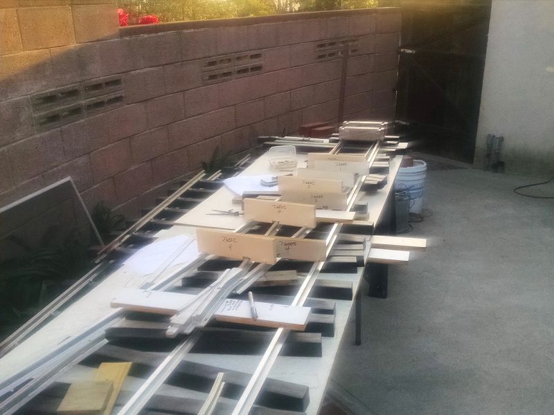
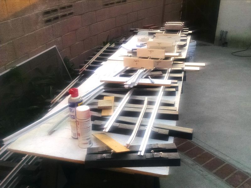
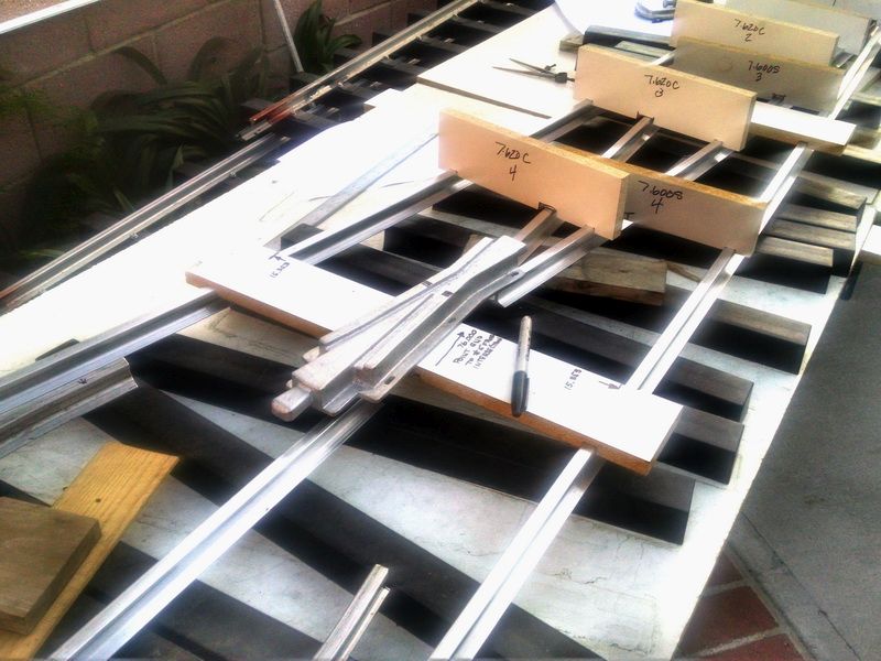
The series of photos below, show the various “fitting templates” and gages I machined, to check track gauge, chord length and arc height. These are positioned in “station points” or positions along the turnout. All the dimensions are based on the distance from the end of the switch points. Also the fitting templates establish the relationships between the curved closure rail and the straight closure rail and their relationship to the main stock rails.

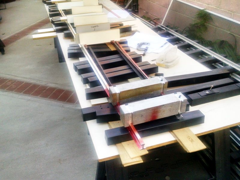
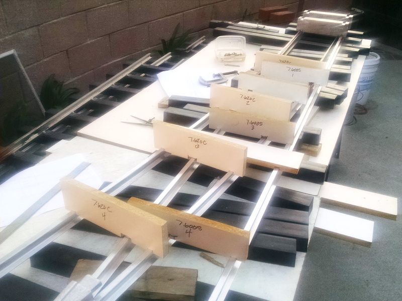
As you can see in this photo, the edge of the fitting template establishes the relationship of the main straight stock rail and the main curved stock rail AND the position of the cast aluminum frog and the ends of the curved and straight closure rails. Everything checks :).

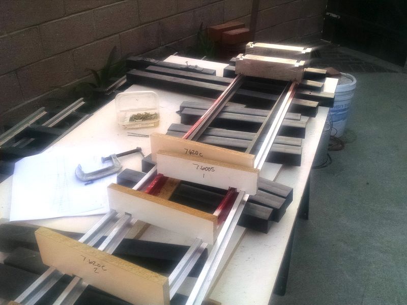
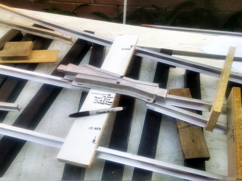
You can see in this last photo that the assemled switch points fit the notch in the curved stock rail very nice.

Somehow it brings to mind lofting a boat hull.

As it happens, 12 inch to the foot scale rail is pretty wiggly too.

To assemble this switch, the company making these “kits” recommends drilling a hole on each side of the rail head at the foot of the rail and 4 inches apart along the length of the rail. When you purchase these as machined/ready to assemble kits, the holes are drilled precisely with a CNC horizontal mill at the factory in Ohio. Because I wanted to build this turnout from scratch and drill the rail in my own machine shop. I had to come up wth a fixture to drill all these holes precisely on center and spaced exactly right along the rail otherwise the tie spacing would be uneven and the track gauge would vary or be out of gauge. A drilling fixture solves all of these problems. The photos below show the milling and drilling operation to make this very simple fixture. In the first photo, I took some scrap 1/2 inch thick aluminum plate (an old engraving job for the name plate on my 1-1/2 inch scale Gene Allen ten wheeler). I milled a .940 wide slot, .100 deep to accept the base of the aluminum rail. About .005 clearance so the rail would be snug in the fixture as I was drilling and still slip easily along as I drilled each successive set of holes. These holes were precisely dialed in on the mill, drilled and reamed with a .125 dia. reamer. The larger hole on the end is the “indexing start pin” to establish the placement of the first holes in the rail which is .200 from the end per print.

You can see the indexing pin hole here at the end of the rail.

Here you can see the relationship of the indexing pin and the 1/8 diameter screw holes.

Here is how the operation works. The first set of holes on the left side of the photo shows the first two holes are .200 from the end of the rail. As I slide the rail through the fixture, I also dialed the fixture over 4 inches to the middle holes in the fixture. I removed the large indexing pin (don’t need that now because the remainder of the holes will be on 4 inch centers. I slide the rail to the left and drop a 1/8 diameter dowel pin in the fixture and through the 1/8 hole I just drilled. Now on the proceeding holes will be EXACTLY 4 inches apart and grouped as pairs, with both rows of holes in the exact position.

Long shot view of the holes that have been drilled already. Because the distance between the spindle of my mill is only about 60 inches from the back wall of my bench and garage, I just drilled as many holes as I could and then removed about 14 inches from the 120 inch long stick of aluminum rail (the print calls for this straight main rail to be 104.5 inches long) and flipped the rail end for end and continued drilling using the last hole drilled and dropping a 1/8 diameter pin in place. I used the same fixture to drill the straight closure rail.

Forrest Scott Wood said:

Somehow it brings to mind lofting a boat hull.

As it happens, 12 inch to the foot scale rail is pretty wiggly too.

Funny you should say that…when I made forging dies for fighter aircraft, passenger aircraft and the Space Shuttle, there were “Water Lines” and “loft lines” everywhere to establish the datum stations throughout the fuselage and wing structure.

Nice job of Model Engineering that (Thumbs up !) .

Gary Armitstead said:

Forrest Scott Wood said:

Somehow it brings to mind lofting a boat hull.

As it happens, 12 inch to the foot scale rail is pretty wiggly too.

Funny you should say that…when I made forging dies for fighter aircraft, passenger aircraft and the Space Shuttle, there were “Water Lines” and “loft lines” everywhere to establish the datum stations throughout the fuselage and wing structure.

Hmm, there’s gotta be a way to model a station at a significant surveying point on your layout and name the station Datum then see who if anyone gets it.

Well today was the big day. All the parts are finished on this big turnout and the day of reckoning has arrived. Now I see if it all goes together and all the geometry lines up to make a good operating 1/8th scale turnout. I started with the straight main stock rail first and drilled and fastened the first tie into place. Next I fastened the end tie on the straight stock rail on the diverging end. All the subsequent ties go against the match board along the entire length of the 104.5 inch long turnout. With the screw holes already drill in the foot of the rail, it was easy to establish spacing. I centered each rail hole in the center of each tie and match drilled the tie. I just “marked” the hole going into the tie about a 1/16th of an inch. Then I finished drilling the pilot hole in the tie on my Shopsmith, with everything straight and perpendicular in the tie. Back to the turnout to open the 1/8 inch diameter hole up to .135 diameter (the tap size drill for a #10 SS deck screw).

Looks pretty darn good there Gary … Do you plan to make another … or buy pre built ?

Dang Gary, that is beautiful!

It must have been almost as much effort putting together that work bench as it was building the switch(https://www.largescalecentral.com/externals/tinymce/plugins/emoticons/img/smiley-foot-in-mouth.gif)

Do the rails get attached to the Frog ?

It doesn’t look like you much to attach the frog to…

Sean McGillicuddy said:

Do the rails get attached to the Frog ?

It doesn’t look like you much to attach the frog to…

Sean,

If you look closely at the photo, you will see the pre-drilled 1/8 dimeter holes in the straight closure rail. and also the elongated cast holes in the frog. The straight closure rail gets screwed to the ties the same way the main right stock rail does (I’m still assembling :)). BOTH the curved and straight closure rails don’t fasten to the frog. The frog is attached to the ties as the rails are, but the frog “floats” separately. The assembly of the turnout is done in the following order: The straight rail is first, then the straight closure rail, using a track gauge fixture to establish correct track gauge. Next the frog is fastened in place in relationship to the straight closure rail.The curved stock rail is next. Last is the curved closure rail checking track gauge to the curved stock rail.

Sean McGillicuddy said:

Looks pretty darn good there Gary … Do you plan to make another … or buy pre built ?

I will probably build another #5 for a siding to park the second train. I know how to do it now and have all the fixtures and gages made. IF I decide to build a #7, I would definitely buy the full on kit with the pre-bent rails, machined notches for the switch points and the CNC drilled holes in the rails and the ties. It just takes too much time otherwise. It was a nice building experience though and gave me the confidence that I could actually build one of these from scratch!

Gary

Any update photo’s of this awesome looking switch ?

Sean McGillicuddy said:

Gary

Any update photo’s of this awesome looking switch ?

Sean,

Thanks for asking…I have been on “light duty” orders from the VA for the past six weeks! I “tore” a muscle (and severe muscle spasms) in my left hip (too much for a 74 year old :slight_smile: ) and now going through “therapy” to repair. Stopped the turnout building right now! Hopefully I can get back to this turnout in a month or so and get it finished. I will build the second #5 switch using the full on “kit” and not do all the machining myself. Just too much work for the extra $425 I would “save”.

I also had a major computer crash about a month ago. The nice part about THAT was that I didn’t lose any of the drawings or photos of THIS project or the build of the Super Husky critter or Baldwin electric projects…ALL 1/8th scale. Back up…Back up…Back up! :slight_smile:

I just saw this thread Gary, wow, gorgeous work!

This all fits in Burbank?!

Cliff Jennings said:

I just saw this thread Gary, wow, gorgeous work!

This all fits in Burbank?!

Cliff,

THX for the compliment. Yes, it “fits” on a Southern California suburban lot of 11k sq. ft…just fits…:)! You might have missed my “other” thread on here about building the short line. Shows where this switch goes and the building of the track panels in 7-1/2 inch gauge. See “Building a Big “little” Shortline RR” in Other Scales Forum.