Large Scale Central

2016 Challenge Build Log -- The Yankee Girl Mine

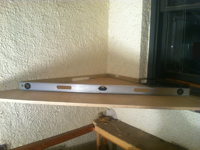
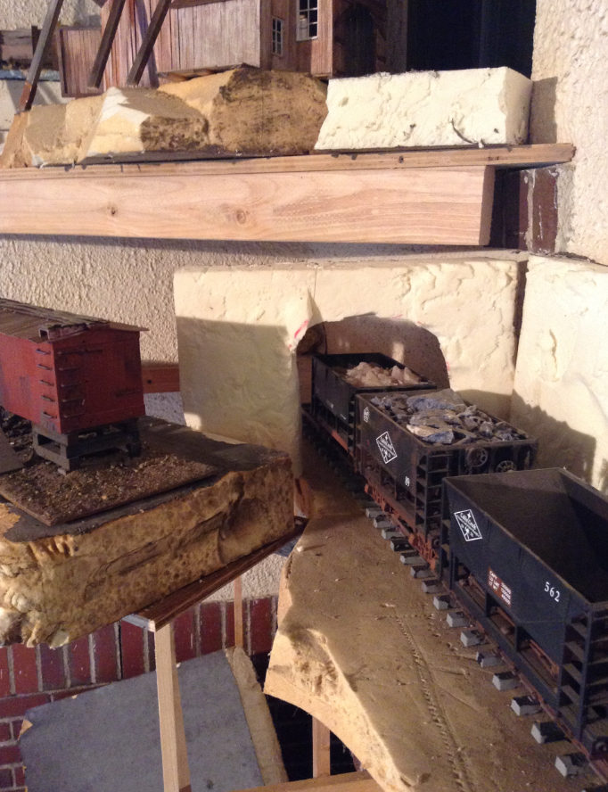
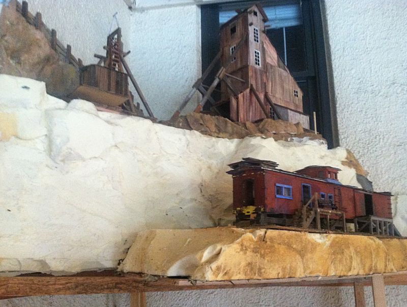
I wasn’t sure whether to continue this thread or start a new one, but it seemed logical to continue this one. I’ve started incorporating the minehead and hoist into a Mining District on my railroad. I found a good spot for it high up in one corner, and the minehead and hoist sit on a triangular base, a shelf basically, which is removable in and out. Then I added a mining office below and there’ll be steps going up to the mine itself. Also I added a tunnel that goes under the district to a fictional mine ore processing center. The raw ore will slide down shutes directly into the mine cars.

Anyway, here are more pictures than you’d probably care to look at, but what the heck.
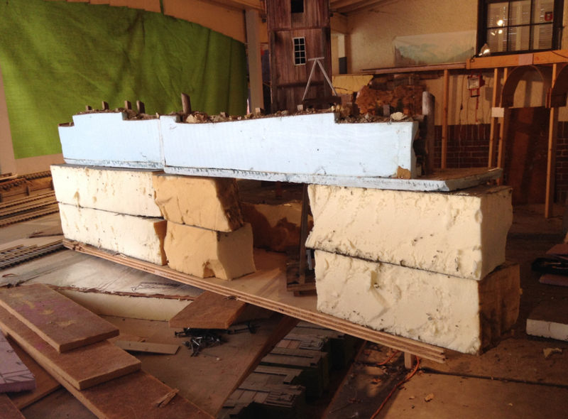
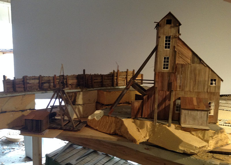
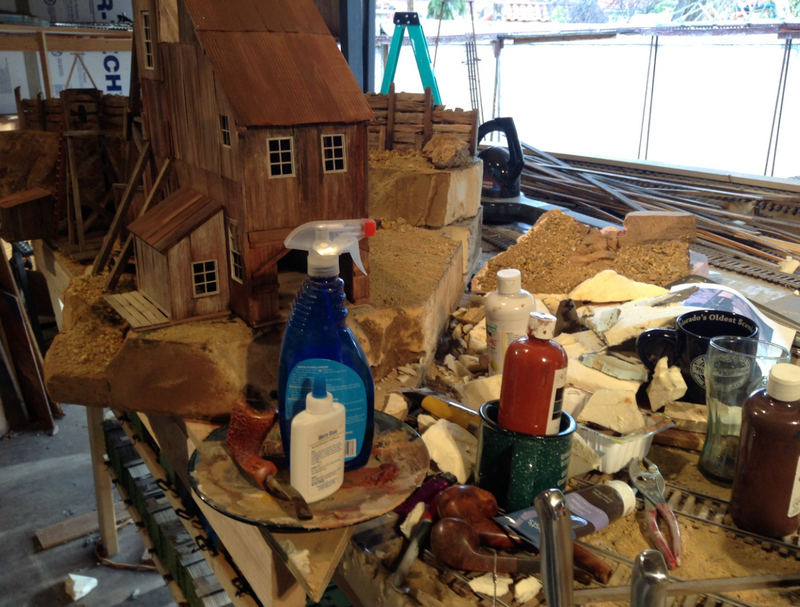
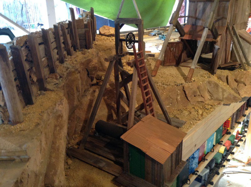
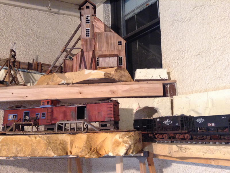
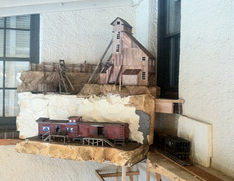
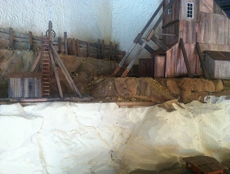
This is the initial placement of the minehead and the hoist, with the minehead sitting on higher “ground.” I am using four-inch deep industrial insulation which I salvaged from a roof tear-out down the street from my shop. I got several hundred dollars worth of this stuff in eight-foot panels for FREE…those roofing guys were more than happy to have me haul it away and keep it out of their roll-off>>>>>>>>>I made a HOME RUN on this one!!!
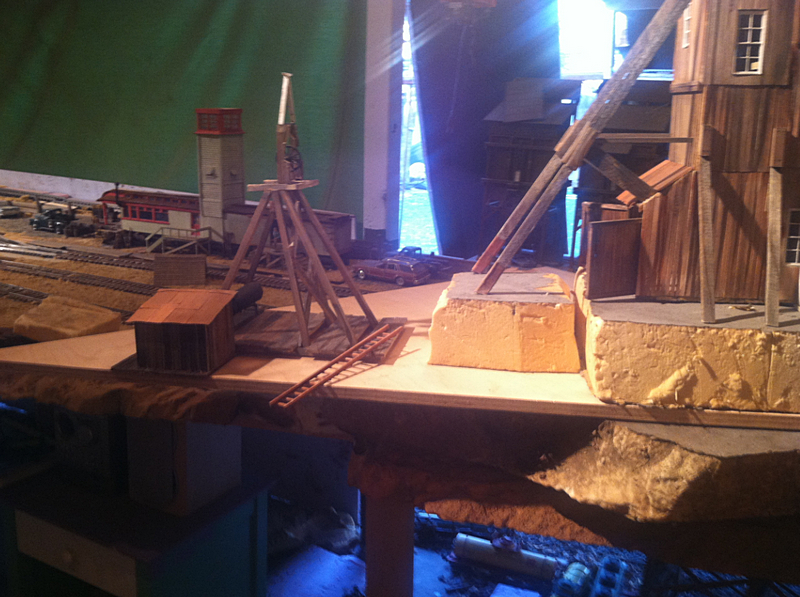
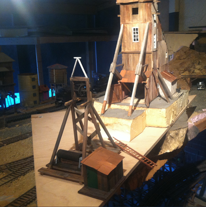
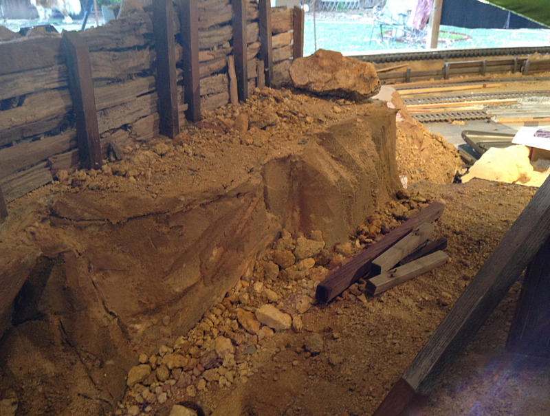
I made a retaining wall for the limit of the district out of pieces of mulch/wood I found by picking through the mulching at the dog park, then glued it all down on a 1/2" base of blue insulation foam.
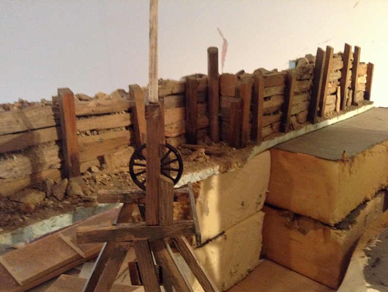
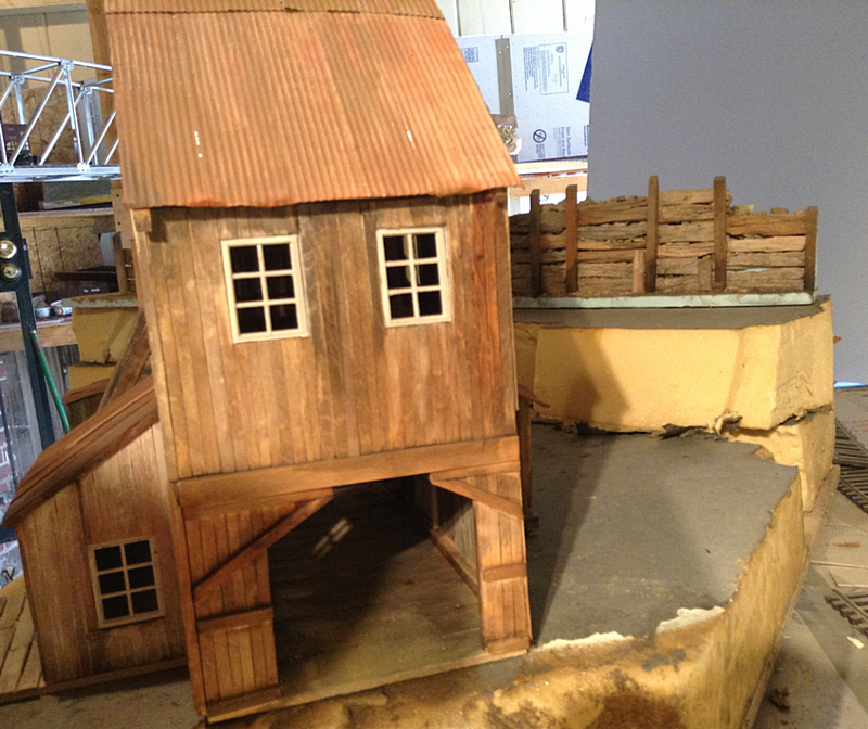
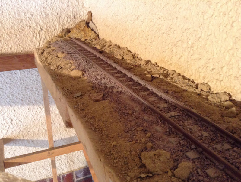
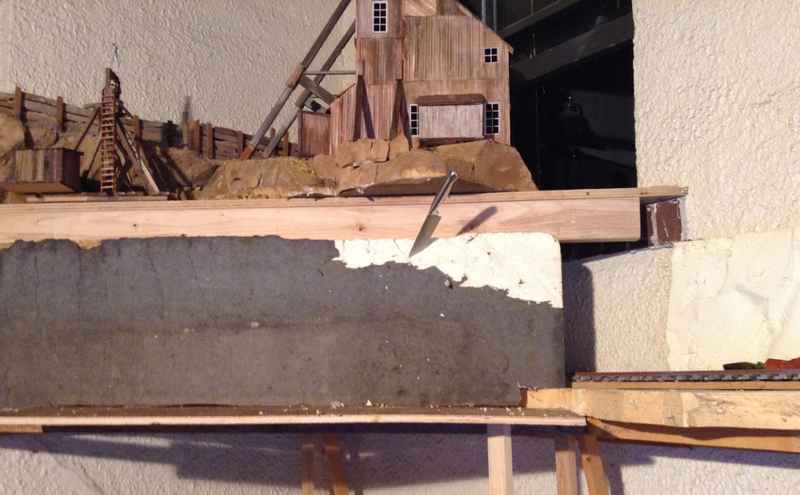
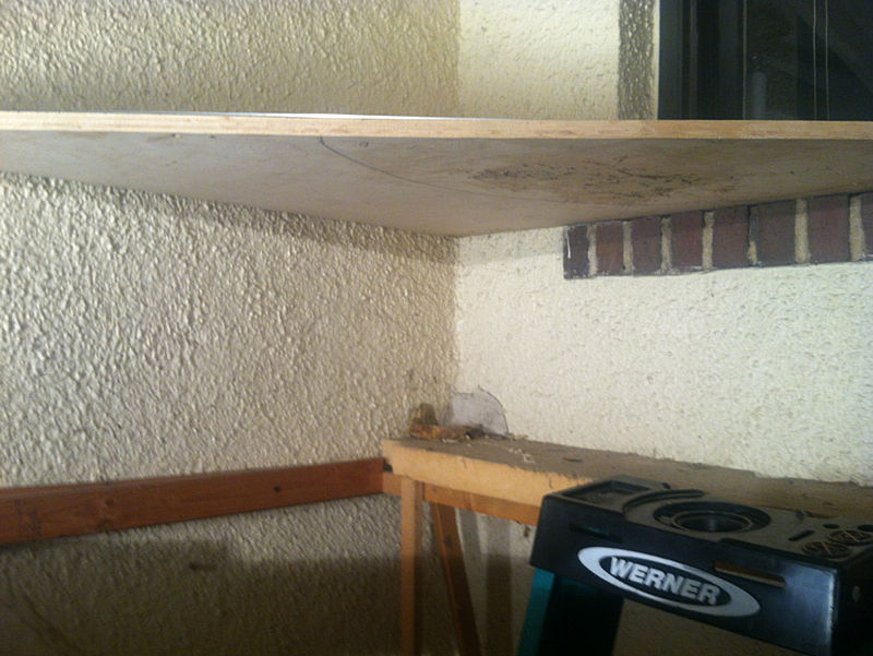
Then here is the “shelf” for the mine office. There is a curved bridge that goes in front of this mining district, but I removed it temporarily to make this build. The mine office will connect with the bridge once the bridge is back in place.
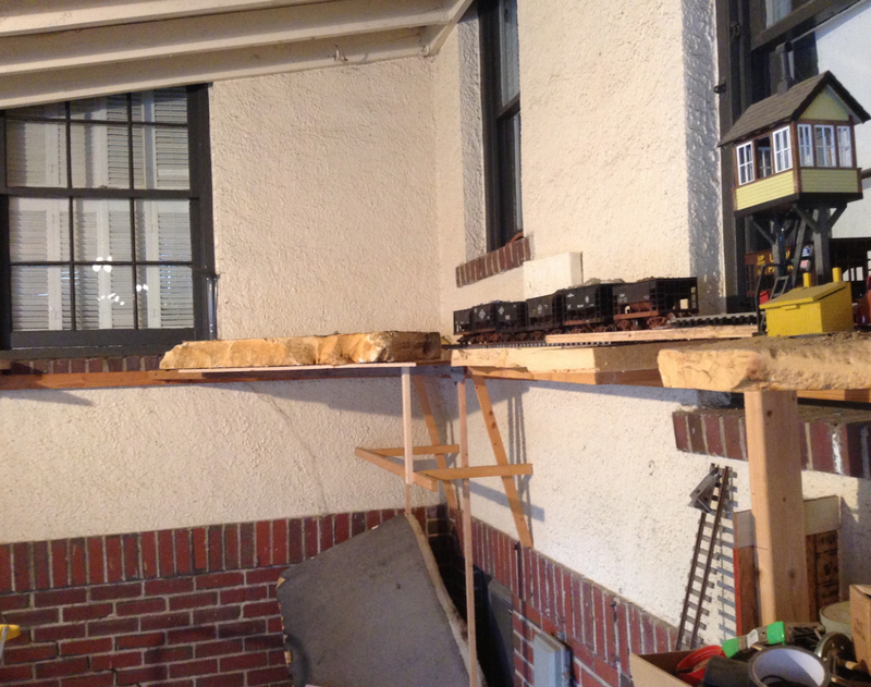
You can see the bridge leaning up against the tracks on the right, and here’s the basic layout of the district.
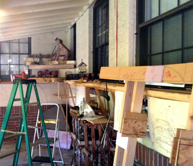
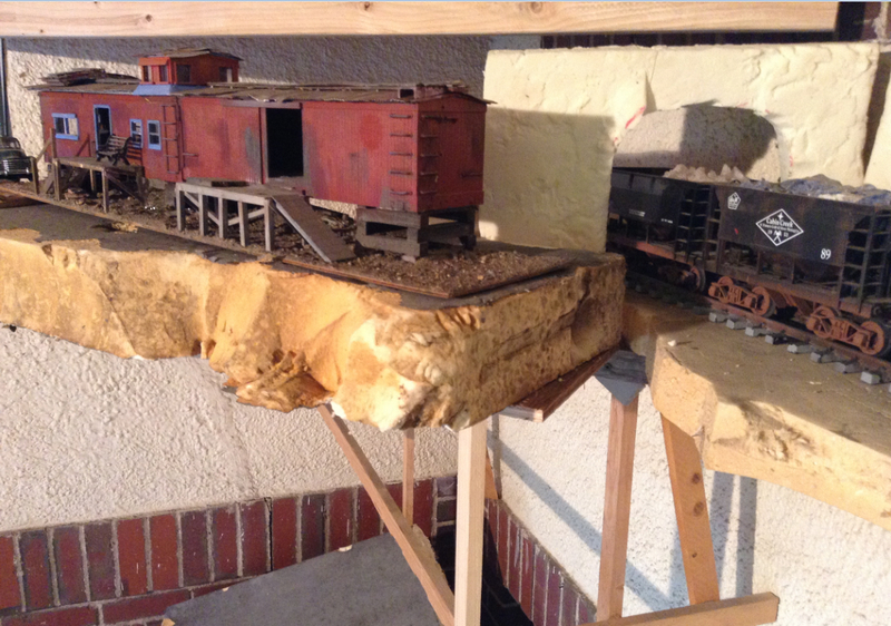
So that’s as far as I’ve gotten. There is so much to do it isn’t even funny. My rock painting really sucks big time right now, not even close to what I wanted. The minehead needs an inner walling to prevent light from leaking out. And there’s a hundred other things to do. But at least I got a start and it’s all in place in a good spot on the layout.

Thanks for taking a look at these too-many photos, and if you have any suggestions, don’t be shy.

edit: like you guys are shy! Ha!

Shy, what’s that mean?

When I was colorizing hydrocal rock castings I used acrylic washes, plus my usual ink stains. I had better results by ‘chance’ than trying to paint them.

Spray bottles and a medium brush to dab it on.

John

That is really cool John! Hey I wouldn’t get too worked up about light leaking through the cracks in the siding… It would done that on the real building too… Should actually look prototypical.

John, you’re right. I don’t know what I was thinking. I’m so used to painting rocks in landscapes, but this isn’t like that, nothing like painting at all actually. I think my carving is good, but I’ll use the basics you describe…get the right base coat down and then wash, stain, dab dab dab!!

Eric, I never thought of that. Good call. Of course the real building would have light shining through the cracks in the siding. I think I’ll get some glazing in the windows and leave the rest pretty much alone.

I imagine using Christmas lights for the entire district. I think. I want to find the ones where when one bulb goes out the entire string doesn’t die. I don’t know how that works. I keep hearing about parallel and straight-line wiring, but I don’t understand it. This will be my first attempt to light anything other than putting dollar-store flashlights in a building like I did a couple of years ago for the challenge. I’d like to flip a switch and Presto!!! lights come on. Any suggestions would be helpful. I read or heard somewhere that low-light automobile lamps work, but I wouldn’t know how to wire those.

I’ll actually have some electric/telephone poles throughout, including the electrical wire that was a t the top of the hoist in the prototype, so maybe the wiring could be functional. That would eliminate the Christmas light wiring but maybe not the bulbs on the wire in the building where you don’t see the wire.

…or better yet, pictures of wiring would be helpful…that way I don’t have to understand it, I can just copy it. Kind of like html code!

awesome

Wiring for low voltage lights isn’t all that complicated, once you grasp the basics. I try to run my bulbs at less then their rated voltage, that way they give a nice warm glow, and they last a lot longer.

Yeah, Maynard, I’ve had it with being mystified by the simple basics of electricity. How complicated can it be? I think I’ve lived long enough without knowing how to wire a damn light bulb!

John, risk a look:

Korm, Thanks for that. I am not good with electrics beyond basic, very basic stuff. Your diagram makes it easy for me to grasp. Last, what voltage to you use on the lights? 26V? Or a bit more. I’m planning on using a standard Xmas strand as you illustrated.

John, great representation of the Yankee Girl Mine. I’m very familiar with it and I think you grabbed the essence. Great job of modeling. I should be so skilled(http://www.largescalecentral.com/externals/tinymce/plugins/emoticons/img/smiley-undecided.gif).

They do make Christmas lights that run in parallel instead of series. They are generally more expensive and if I am not mistaken they have a third wire twisted in there but don’t hold me to that. The concept of series and parallel wiring is pretty simple and people can get overly confused by it.

I don’t really get it very well, I can do it, but I can’t explain it. I do know that Korm’s drawing is a great simplified drawing. The voltage required on a parallel string is determined by the individual bulbs rating. So if a bulb is rated at 12v then the power supply needs to be 12v (or lower as David M mentions) Since each bulb will receive the full un-shared voltage. What needs to happen is that there is enough amperage to run the number of volts required. You won’t be able to run 10,000 12v bulbs on one amp even though your giving them the voltage they require you are not giving them enough of it.

So Rich the transformer in Korm’s parallel diagram has to be rated for the correct single bulb voltage and have enough amps to feed the the total number of bulbs.

The small Christmas lights are usually rated at 3 volts.

I wasn’t trying to be insulting with my comment, but all too often the concepts aren’t explained simple enough, for folks who aren’t familiar with the subject to grasp.

Using Korm’s instillation, the standard Christmas lights are wired in series. The current needed for that string is what one bulb would draw, at it’s rated voltage. The voltage needed would be the sum of all bulbs in the string. So if they are 3 volt bulbs (for example), then you would need 5 (since there are 5 bulbs) times 3 (the bulb’s rated voltage), for a total of 15 volts.

The what you want illustration is wired in parallel. The voltage applied from the transformer would be the rated voltage of the bulbs used. The current needed would be the sum of what each bulb needs to operate. So if each bulb would normally draw 100 miliamps (again just for example) and there are 5 bulbs, then the transformer needs to be able to supply at least 5 times 100 miliamps (.1 amp), or 500 miliamps (.5 amps). If the transformer can supply more, then that’s better. That way the transformer isn’t being taxed to its limit.

David I knew all of what you said but I couldn’t figure out a way to say it. That was a great simple explanation.

Thank Korm for the picture. I just put some words to his illustration.

Thanks Korm and David and Devon, I think I get it. I’m assuming the red is the electricity and the black is the neutral. The standard string of lights, in the diagram the bulbs themselves are actually part of the continuous red electrical line, so when one bulb goes, the line is broken and all the bulbs go out; you don’t know which one went bad, could be any of 'em. Which really sucks when the light burns out. In the other one, the parallel one, each bulb has it’s own red line source of electricity (the red line branches off individually to each bulb), so you know which one went bad.

I don’t get the point of the neutral black line, but they’re everywhere and nothing works without them so I won’t worry about it.

Now when you have the transformer there in the diagram, could that be a dimmer? Like a regular light switch dimmer? If that’s possible, I don’t have to worry about volts and all that, just dim the lights to where I want them? Also, I wouldn’t have to calculate the things Devon was explaining.

So in practice if I want to run the wires through holes underneath the structures then I use extra Christmas light wire. If I want to run the power to the lights from model telephone/electrical poles, I need to find wire that’s the right scale diameter and flexible enough to look like power lines. Hopefully I can find something black so I don’t have to paint them. Do you know of such an animal?

p.s…thanks for the kind words Rich…it’s a work in progress, but I’m getting there.

John,

The black wire in the diagram is defiantly a neutral and is absolutely necessary. Electricity can be viewed for us laymen in terms of flowing electrons though it not how it works. This is not really how it works but it helps to visualize electricity as water and a light bulb as a water wheel. Electricity must flow in and then flow out in order for it to work. In a water wheel it wouldn’t work if it only flowed in and stopped with no pathway out. Same idea. though for different reasons both AC and DC must have that return path which ultimately leads to a ground. Your neutral is a ground and is attached to a buss bar in your panel that is attached to some ground source. So power coming in on the pole heads through your panel to whatever your powering and then back to the panel on the neutral and then to ground. It has to have a path to ground to work. Also don’t get confused with the red and black, typical AC house wiring at least here in the USA is black is your hot and white is your neutral and green is your ground.

Now if someone could please explain why we need a ground in an AC house wiring scenario. The white and green end up attached to the same buss bar.

OK not transformers are not dimmers. I don’t understand dimmers at all but I know they are not the same thing. I can’t answer whether or not that is a viable option.

Rich Niemeyer said:

… what voltage to you use on the lights? 26V? Or a bit more. I’m planning on using a standard Xmas strand as you illustrated.

well, now it gets complicated.

if you look at a light-chain, most often, there are more than two cables from the plug to the bulbs. - meaning, that there are two or three “standard strings” on that chain.

to find out the voltage, each bulb needs, i just pluck out one bulb. counting the not burning bulbs, plus the empty socket. (let us say, the example-result is 33)

then you divide your household voltage by the number of bulbs (so 120V / 33) the result is the voltage of your bulbs. (in the example 3.6 V per bulb)

… meaning, that you would need a powersource of 3 to 4 Volt for the second chain, i drew. (i would take only three volts. nicer/dimmer light, less bulb-changing) the more bulbs you put on one string, the quicker your battery is empty.

if you are a lazy, cheap junk-modeller, like i am, you don’t want to change -and pay- batteries every few days or weeks.

then you would go hunting for either an old computer power brick, an old wireless-telefone transformer (8 or 9V) or an old H0 controller/transformer.

the computer power pack should have a 3.5 outlet, the H0-transformer you can adjust by eyesight.

with the 9volt transformers, you make strings of the standard type (the upper in my drawing), that are three bulbs long. (as i can count to three without problems, i think it is possible to find out which bulb of three is rotten…)

then bundle some of these short strings to the connection of the telefone transformer.

now you got two possibilities:

either ask somebody with knowledge to measure/calculate, how many short strings your transformer can stand, or, like i do, put a finger on the transformer. (if the transformer feels too hot, take off one or two of the short strings)

John, the black neutral:

in simple words, every use of electricity is a “short-circuit”. and as you can not produce a short without two cables, you need that thing, to complete the flow-circle of the electrons. (just like buying beer. buy the full bottle, drink, return the empty bottle… ;-))

and, yes, a dimmer should work. or an oldfashioned loudness-regulator dial from an old steam-era radio.

but, if you are connecting without a transformer, i would not use wires, that can be touched by accident. (you could grill yourself)

oh…

i just read Davids explanation.

and i would like to add, that these 500 milliamp would be at 3 volt. (if i’m not mistaken)

Korm, would an old Lionel power supply work as a variable power source for a string of AC Christmas lights? Since Lionel powers supplies provide AC current to three rail tracks? I assume the current to the tracks are AC…or not?