Large Scale Central

1/8th scale Baldwin Westinghouse Electric Freight Motor

Rick Marty said:

Very cool stuff Gary, your ability using those programs astounds me. Just out of curiosity how does riding behind that locomotive work out with that trolley poll sticking back in your face?

Rick,

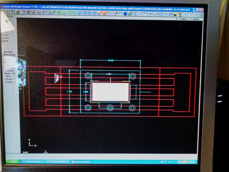
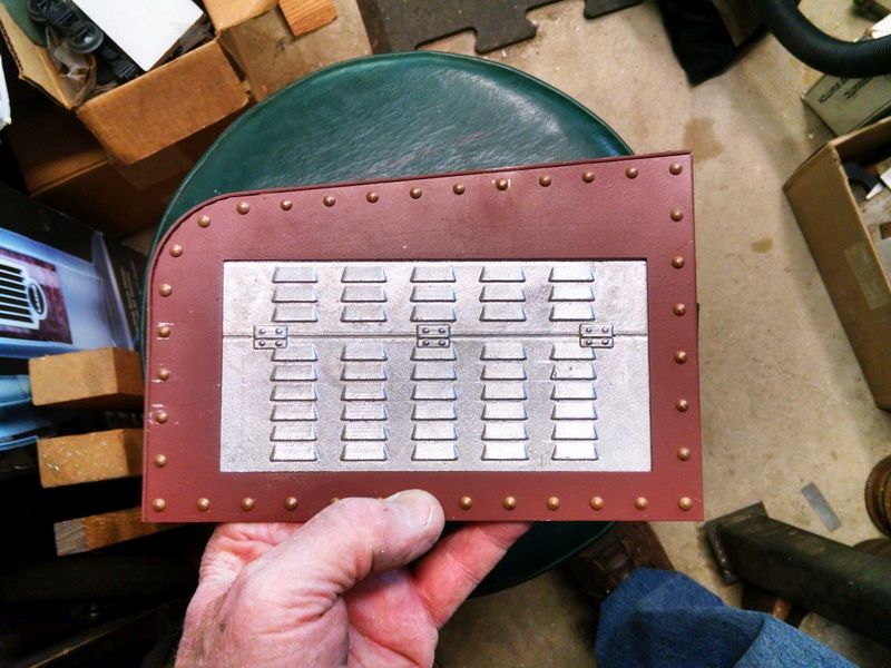
I have been using MasterCam since about 1992 or 1993. The last die shop I worked for before my retirement wanted to get into NC milling of forging dies. So the owner and I decided we needed to learn the software so when he purchased a new Haas horizontal CNC mill ($150K+ investment), we had no choice but to take the risk and get it done. Lots of head scratching for a year or so, lots of frustration during the learning curve (lost some money along the way. But eventually everything “clicked” and we were on our way. Never looked back. I have been convinced to try Fusion 360 from a number of folks on the Chaski (Home Machinist website) and quite a few vendors that sell detail 3D printed parts for the ride-on scales. The Fair Weather Foundry back in Kent, Ohio is owned by a guy named Marty Pinkston. He started using 360 a few years ago to make molds for detail parts in 1" and 1.5" scale stuff. He was the one that cast our louvered doors for these Baldwin engines using ONLY a photo I provided of the prototype. The technology just “begs” to be used now. And because the software is free to hobbyists, you really can’t pass it up. I actually needed BOTH software products to get what I showed in the previous post. I am faster in drawing in MasterCam than 360. And I can surface a part faster in MC. But 360 gives me the ability to get the files converted to a format that Shapeways or any other 3D vendor can use. They are all just “tools” and I use what I feel most comfortable with. &5 is “probably” a little late to be learning this stuff, but it does keep the “gray matter” from decomposing!

As far as the trolley pole getting in your face when running these engines, the fact of the matter is that the trolley wheel on the end of the pole sits just above the center of the rear coupler. Never gets in the way. The total length of the finished pole is a little over 26 inches. Take a look at the first photo of the prototype #1624 engine and you can see that it falls short of the end of the locomotive. So that is not an issue.

Great set of posts. Great work!

As a one time model engineer I just love ''em .

Gary, I have thoroughly enjoyed following this project and the detailed description of each phase of it that you have posted. The craftsmanship on this project is marveled only by the way that you presented it.

Man …He’s good @ this Ha ! … How much is left for this engine?

Sean McGillicuddy said:

Man …He’s good @ this Ha ! … How much is left for this engine?

Sean,

My wife keeps asking me this same question…“maybe” six months to complete. Depends on the PE trolley pole castings. Still waiting for a response from Marty Pinkston at Fairweather Foundry in Kent, Ohio. We are hoping that the castings will show the detail we want for this engine. I will be discussing the molds with the owner of the foundry because some of these castings involve multi-level “parting lines” and locks. I will do a drawing in MasterCam to show what the molds will look like and post them. Lots of “die design” experience needed to do this correctly. BTW, thanks for the comment :).

While waiting for the response from our foundry on the trolley pole castings, I started the milling machine work on the cast aluminum louver door panel castings we received from the same foundry late last year. There is a small edge that gets milled into the casting so it will fit the same opening in our sheet steel hoods. Because there are four of these panels per engine and all of them have to fit the same rectangular holes, it’s always best to make a “fixture” to hold the part. No guess work on location for multiple parts. I have eight panels to do for TWO engines, so the fixture was mandatory.

Photo below is a screenshot of the fixture with the template of my mill table embedded in the drawing. This helps with the locations of hold down clamps and bolts for both the fixture and the part. Make the “mistakes” on the computer, not in the shop :)!

Then go out in the shop and make the fixture and attach to the mill table.

Fixture is just a “quick and dirty” build. I used 3/4 poplar, machined BOTH sides flat and true. Machined a nice “match edge” on one side so it lines up the same way each time the fixture is put on the mill table.

Used my pin nailer to fasten two match strips to the fixure while it was still setup and took a "skinny cut on the match strips so they are exactly square and poerpendiculat to each other. No guess work this way. Tried the louver casting and sits nice and square in the fixture.

The small amount of shimming used UNDER the casting is so that the FACE of the louver casting is straight and true to the hood opening… I do the long cut first and then use the side clamps to hold the part. Remove the end clamps and proceed to mill the end flats. By using the dial readings on the mill, each part is indentical.

Thusly :)…

First panel tried and fit in place. Just seven more to go. Have those finished tomorrow.

Gary it looks like you’re still having fun … using tools and working on train related things…

Very nice work …(https://www.largescalecentral.com/externals/tinymce/plugins/emoticons/img/smiley-laughing.gif)

I had some time today to do the painting on the aluminum lover door castings. Nice warm day for this work (85 degrees today-sorry East Coast :slight_smile: 
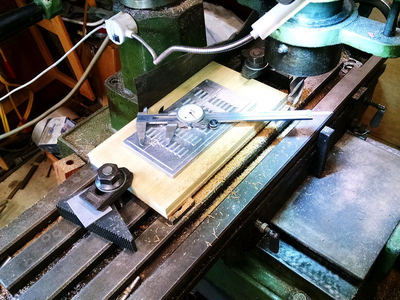
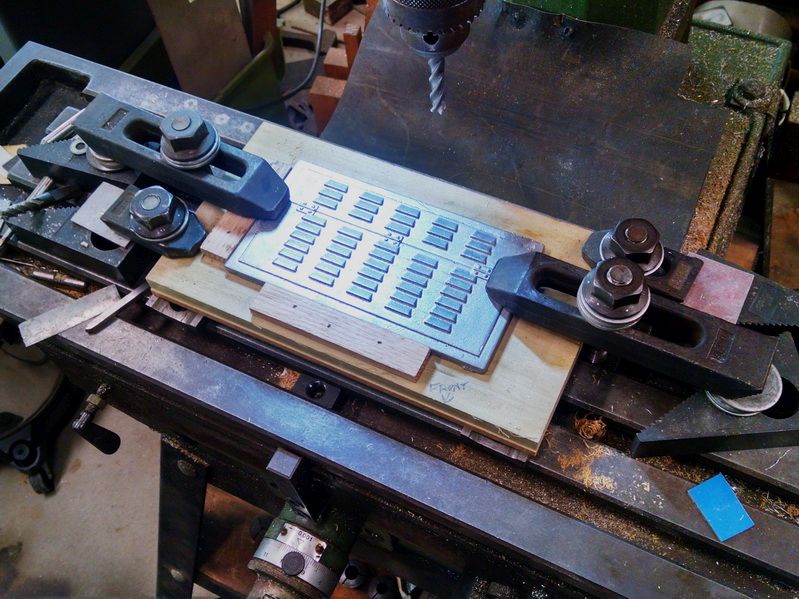
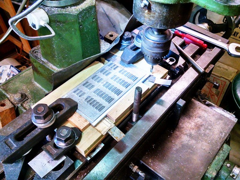
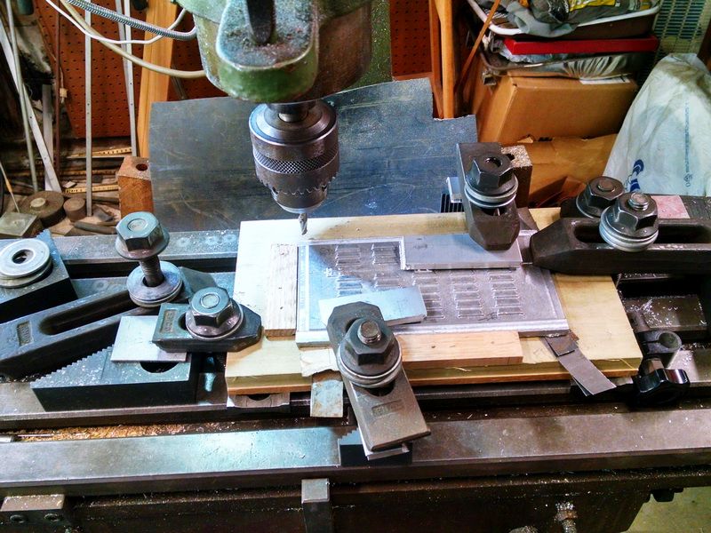
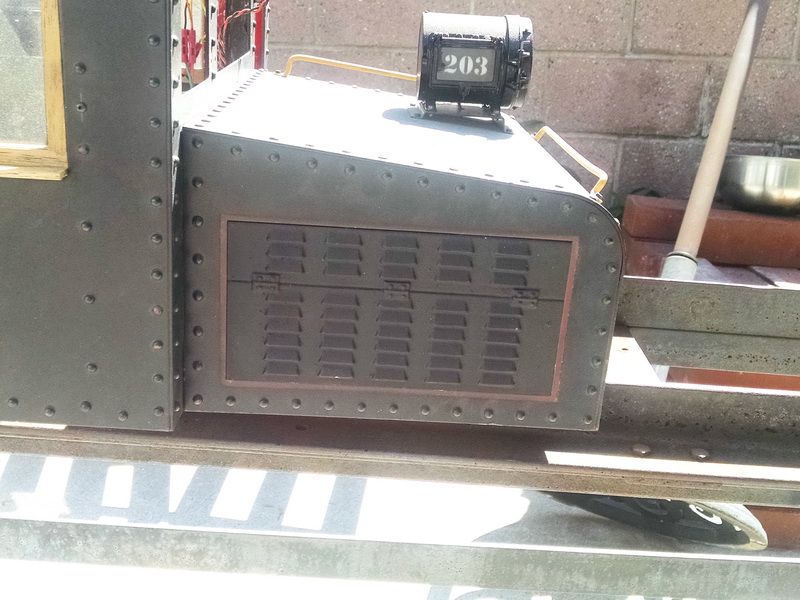
). A couple of photos taken today and the last one, shows one of the lover door panels install on my old Baldwin electric.

I had a little file work to do on some of these castings where the sand mold gave way during the “pour”. Not too difficult to do with small needle files. I don’t think you can notice the “flaws” in these photos. There is a saying in the ride-on hobby…Painted black and 5 feet away, you’ll never notice it!

The area around the louver door opening still needs painting (the entire cab body will be repainted and relettered with custom decals from our own Stan Cedarleaf (already purchased) The reddish brown area is where the old louvers were located.

Now to go outside (out of the air conditioned house :slight_smile: ) and get the other four grills painted.

Just caught up with craftsman build

It is truly amazing work

The rivet counters should be happy … very nice detail … (https://www.largescalecentral.com/externals/tinymce/plugins/emoticons/img/smiley-laughing.gif)

Gary,

Great work on the Class A. The Illinois Traction Society Spring Issue 2019 has a complete write up on these units, that they created in their Shop. Would you like a copy of it?

Ric Golding said:

Gary,

Great work on the Class A. The Illinois Traction Society Spring Issue 2019 has a complete write up on these units, that they created in their Shop. Would you like a copy of it?

Ric,

Yes I would :). Is there a link for it?

Sean McGillicuddy said:

The rivet counters should be happy … very nice detail … (https://www.largescalecentral.com/externals/tinymce/plugins/emoticons/img/smiley-laughing.gif)

Sean,

Thank you AND they are the “real deal”. Solid copper, round head. Each one personally hand-riveted in place. They truly hold the cab together :).

Gary Armitstead said:

Ric Golding said:

Gary,

Great work on the Class A. The Illinois Traction Society Spring Issue 2019 has a complete write up on these units, that they created in their Shop. Would you like a copy of it?

Ric,

Yes I would :). Is there a link for it?

I don’t think so, send me a private email and I’ll mail my copy to you. Ricgolding at yahoo dot com.

You “might” be interested how I transport two 350 pound model engines to my local club to run…pretty easy (I didn’t “keep the new boxes” these came in :slight_smile: ). Simple white oak rack with two sets os couplers and two ratchet style tie-downs over the cabs.

Bring the engine up on the “lift rack” in the foreground and roll right into the wagon.

These couplers are solid cast aluminum “dummy” couplers". They are the best for locking a locomotive into place in a car, pickup or trailer because the knuckle is non-operating. Once the engines are locked in place, then I use c-clamps on the rail to keep the engines snug and keeps them from rolling at all. 700 pounds total for this Volvo wagon is probably the limit for hauling.

Ahhh an XC 70 …that’s my forte’…it will transport just fine as they have high load rated tires and springs from the factory.

(https://www.largescalecentral.com/externals/tinymce/plugins/emoticons/img/smiley-wink.gif)

Try and keep most of the weight towards the front and you will be just fine

Thanks Rooster…This Volvo has the tow package, so I am assuming the springs are rated for extra load from the factory. About 70% of the total engine(s) weight is forward of the axle and yes, the tires are rated “high load”.

Image result for Stupid Car LoadsImage result for Stupid Car Loadsshouldn’t be a problem .

As the Cartalk boy. Click and Clack would say its no heavier than a couple of mother in laws in the backseat. (http://www.largescalecentral.com/externals/tinymce/plugins/emoticons/img/smiley-surprised.gif)