Large Scale Central

1/8th scale Baldwin Westinghouse Electric Freight Motor

Just to show that we just don’t spend ALL of our time working on these engines. We actually run them too. A few photos below of some of these engines operating at Los Angeles Live Steamers club track.

This first photo shows our electrical guy testing three of our engines as they were “MUed” for the first time. My son on the right and my old college professor on the left. John our electrical guy bending over the lead engine (first of three completed for the professor) in the consist checking connections and MU cables. My 35 year old Baldwin electric “resurrected” in the center and my son’s new engine at the rear. All three operated by one hand controller. 1050 pounds of locomotives in this consist!

My son and granddaughter at LALS Spring Meet 2015.

My son running three electrics at LALS coming eastbound through the tunnel from the Western Division side of the club.

When we first started this project back in 1994, all of the details specific to Baldwin electrics were still available in 1-1/2 inch scale. A vendor in New Jersey, Mercer Locomotive Works, was still making these parts at that time. But by 2013 when we started this “build” again, the vendor was out of business or just not making these parts. I contacted Mercer Locomotive in 2014 and talked to the owner. He said he no longer had the patterns to cast the parts, but if I sent my originals back to him, a could either make new patterns or a mold. Either way this was going to be pricey. Because I had the computer technology, he asked if I could draw the parts from my originals and send the information back to him, he would be able to 3D “print” a new pattern and molds. No cost to us to do this. I just gave him the rights to use my drawing. A few weeks later, we had 20 sets of brand new sand hatch bodies and covers… Exactly like the originals!

Mercer Locomotive still sells the shorty coupler pocket in cast iron. First the original on my old electric…with Mercer Locomotive cast bronze coupler.

New engine with Mercer cast iron coupler pocket. We use Tom Bee cast steel couplers on this engine.

Poling pockets and new cast iron pocket for a shorty coupler.

The PE Baldwin engines used Adlake caboose marker lamps. The photo below shows the Adlake lanterns in the PE #1624 at the Orange Empire Trolley Museum in Perris, CA.

For our models, we chose 1/8th scale Adlake caboose marker lamps made by Railroad Supply Corporation in Nashua, New Hampshire. Mounting brackets, fresnel colored kens and lens bracket details all included. Material is cast bronze in a jewelry casting foundry.

Installed on the cab.

The original headlights for the Baldwin electric project at Los Angeles Live Steamers in the early 1980’s were purchased from Mercer Locomotive in New Jersey. When we wanted to purchase 14 headlights (models of Sunbeam Golden Glo), we naturally went back to Mercer. I was told by the owner that he would have to start a new production run for these because he had not made any for a few years. He was asking $275 each and they were in “kit form”. We needed to put down half for a deposit to start production. About $1900 to start and we weren’t sure how long we would have to wait for the production to be completed.

So we contacted a Master Model Maker that belongs to LALS and started discussion on having 14 headlights made. Jack Bodenmann is the Master Model Maker and we knew he did excellent work. He was also one who was always contracted to add the “fine jewelry” to one-of-a-kind locomotives where “the amount of money wasn’t a factor” :). We finally agreed on a price of $420 each, but these were finished models ready to be mounted on the engines. Also the detail and craftsmanship was far superior to anything out there. He also was not asking for any funds “up front”. We were never sorry we made this decision. We made our order in early 2015 and received our headlights in July 2015.

The first sample prototype of our order.

Some photos of how these headlights were made.

Spin casting copper reflector, delryn bulb adapter and a Krypton gas bulb.

Headlight assembled with polished copper reflector. This reflector is chrome plated when finished. There are 12 separate lost wax castings in this headlight.

Number boards. 3 layers of photoetched glass.

Rear of headlight body. Bulbs for lighted number boards.

Photos below are the headlamps I received for the new engine. Photos don’t do these “justice”.

Note the curved headlamp glass. Nice touch.

Miniature conduit for the wires.

Photo-etched 3D Sunbeam builders plate.

Miniature model electrical junction boxes. Bronze lost wax castings and the lids are threaded and work.

Headlamps and junction boxes mounted and wired.

When we saw how nice the new headlights were for my son’s new Baldwin, I decided to get my original Mercer Locomotive headlights restored by our Master Model Maker. I removed the 35 year old headlights from my old engine and sent them off to be restored.

Photos below show the condition of the old headlights after 35 years.

The new “restored” Mercer Locomotive headlights two months later.

New headlight access door and ring castings, new photo-etched glass custom numbers, new copper reflector casting (chrome plated) and Krypton bulb. They also have the nice curved headlamp glass. The MMM also added the builders plates. Yesterday afternoon, my electrical guy came by the house to replace the old control board for the headlights and installed a new board. The reason for the change is that both the new lamps and the restored old lamps now use a positive ground system. These lamps are designed for steam engines and can use miniature operating steam generators for power. Our electrics are negative ground. These boards separate the two types one from the other, so no grounding problems. I tried these new headlamps last night after dark and they throw my shadow across the street from my garage. That distance is about 150 linear feet. Should be more than adequate for night running at Los Angeles Live Steamers track. The electrician also has a dimmer switch on the hand controller (high beam/low beam). The intensity of BOTH beams are adjustable with “pots” on the inside of the controller.

Comparison of types of bulbs used in both headights. The light on the left is the old Mercer Locomotive headlight that our electrician had replaced the incandescent bulb with an LED. The headlight on the right hand side is the brand new Jack Bodenmann light with a Krypton gas bulb. We felt that the Krypton bulb was much closer to the “warm” look of a prototype Sunbeam Golden Glo. The LED is too “toy-like” and the color is too “cold” looking.

$900 worth of headlights per loco, wow… but they are indeed “jewelry”…

Greg

Greg Elmassian said:

$900 worth of headlights per loco, wow… but they are indeed “jewelry”…

Greg

Greg,

The large scale “ride-on” hobby can be pricey in SOME items…but the majority of stuff is comparable to Accucraft “quality” and price. The 1-1/2 inch scale caboose marker lamps from Railroad Supply Corp. (shown in a previous post on this thread) are sold at a reasonable price of $75 a pair. Most headlights sold in this scale are usually in the $150 plus range, but are NOT scale models! These lamps ARE scale. Jack Bodenmann (MMM) has been well known in this hobby for many years as the man to go to when you want a locomotive to be well detailed. His models are all handmade. He never uses “off-the-shelf” items. You never ask “How much”. Most of the engines he details are valued at the start at around $100K. He takes the locomotive from there.

The photo below shows one of my prized 1/8th scale models. A scale model of a Pyle National MO-5 steam generator. This was handmade by Francis Moseley in Flintridge, CA (near Glendale). Greg, you might have known him as he was an inventor and financial backer in early Hewlett-Packard days in the 70’s and 80’s. When I started my 1-1/2 inch scale live steam ten wheeler in 1980, I heard about these working generators from members of Los Angeles Live Steamers. So in 1981, I contacted Francis, talked to him on the phone and ordered one that day. $200 at that time including hand typed instructions, scale conduit, teflon-coated wire (avoid heat around the boiler) and a working steam regulator (to hold voltage consistent while steam pressure goes up and down). I sold my steam last January (running on air, but not completed) and the generator was never mounted to the engine. Bottom line on this generator now is that IF you can find one (very rare), the price is usually around $2500. Many of the nicer detailed engines at our club have Moseley generators on them and they light the headlamp and cab lights. Pretty nice to hear that high pitched sound running the lights during a night run. Just adds so much to the atmosphere of the hobby.

This thread is just about caught up to “today’s build”…

For the past couple of months, my son and I have been experimenting on various ways to rivet these cabs together. Many years ago, I hand riveted the tender for my 1-1/2 inch live steam ten wheeler. That tender had about 1100 3/32 diameter copper rivets. This was back in the middle 1980’s. I was a lot younger and had a little more energy that I have today. Tender took about a week or two to complete and that was the first rivet job I had done.

We asked around the hobby and got as many opinions as there are people in the hobby! Hand rivet…rivet with a pneumatic riveter…use steel rivets, less damage to the rivet head…copper rivets, easier to mash the backside stem…

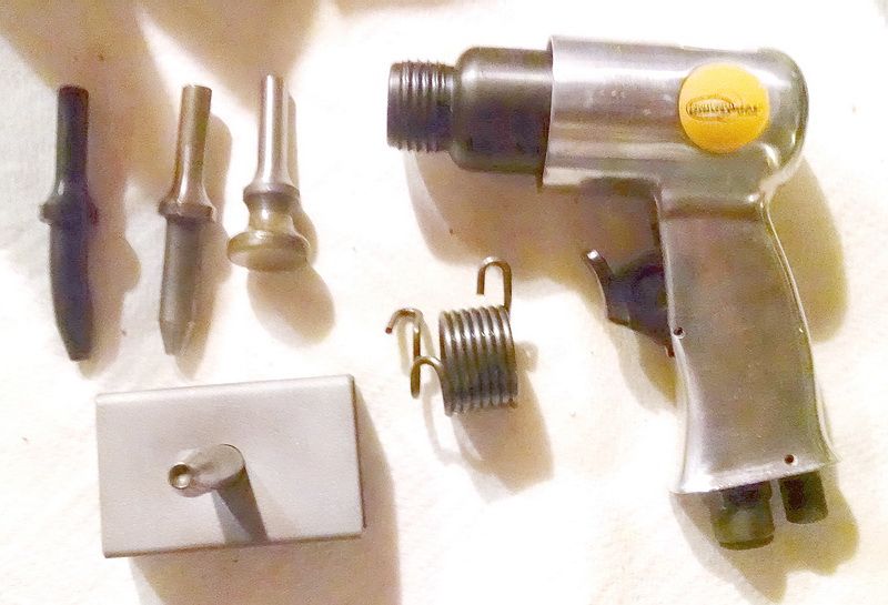
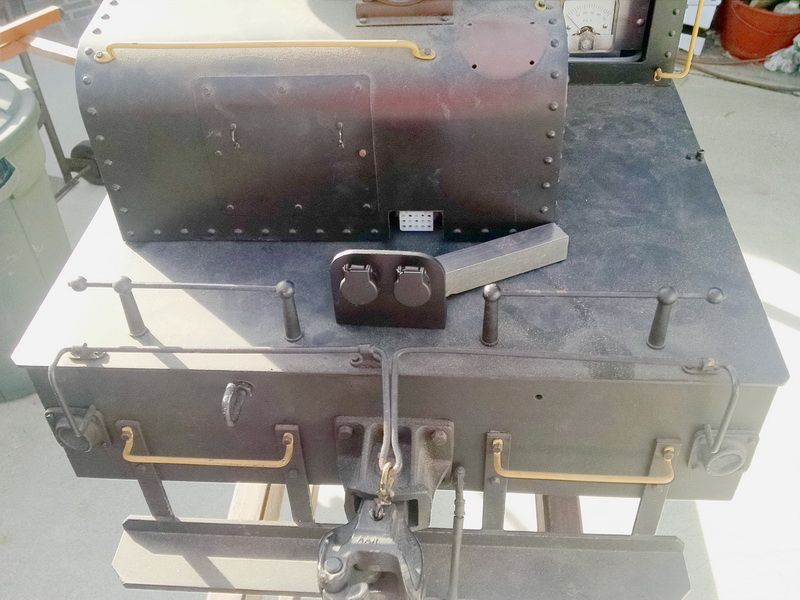
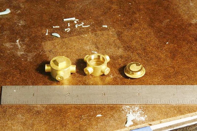
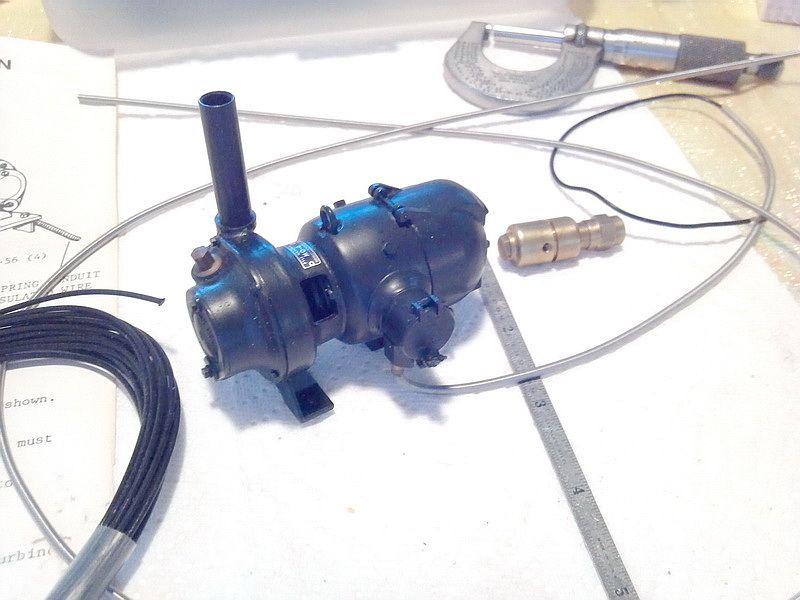
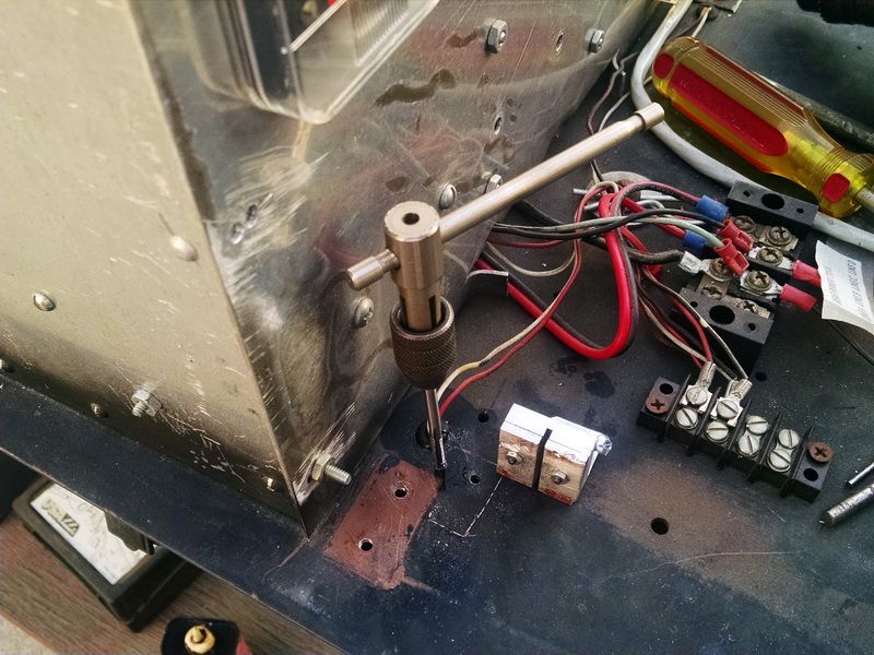
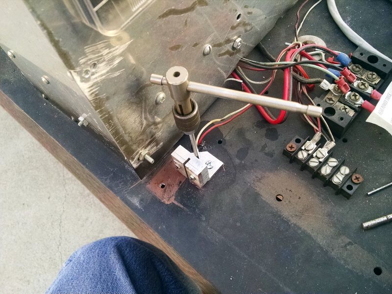
We purchased this rivet gun and punches and the rivet “buck” (tool at the lower left hand corner of this photo with the dimple for the rivet head) from a vendor who does rivet tenders for the hobby as his business. He recommended using steel rivets and using the “buck” on the head of the rivet rather than the “usual” way of using the buck on the tail of the rivet. We tried this on some sample steel rivets he sent. To mash the tail of these rivets, we had to set the pressure on the gun at a fairly high point. We DID mark the heads of the rivets and the mashing of the tail wasn’t consistent. We went to Hanson Rivet Company (well-known name in aircraft riveting) here in Pacoima, CA and talked to the guys in tech support on how best to do this job. Their recommendation was to use copper rivets only and get the proper lengths of rivets. 1/16th inch longer than the total of the pieces being riveted together. This was the best tip we got out of this discussion. Made all the difference in the world! Next they recommended we use a simple hand riveter to do the job. Easier to set the rivet and greater control over the mashing of the tail of the rivet.

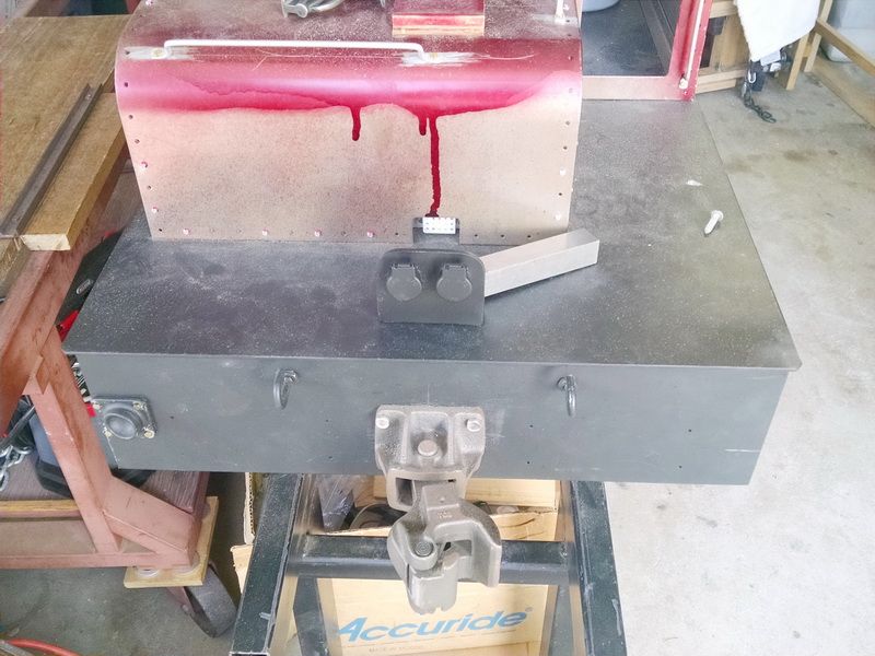
This is the rivet set we used…my old one from back in the eighties!

Pretty simple actually. The buck side for the head of the rivet is on the bottom. The top arm does the mashing of the tail of the rivet.

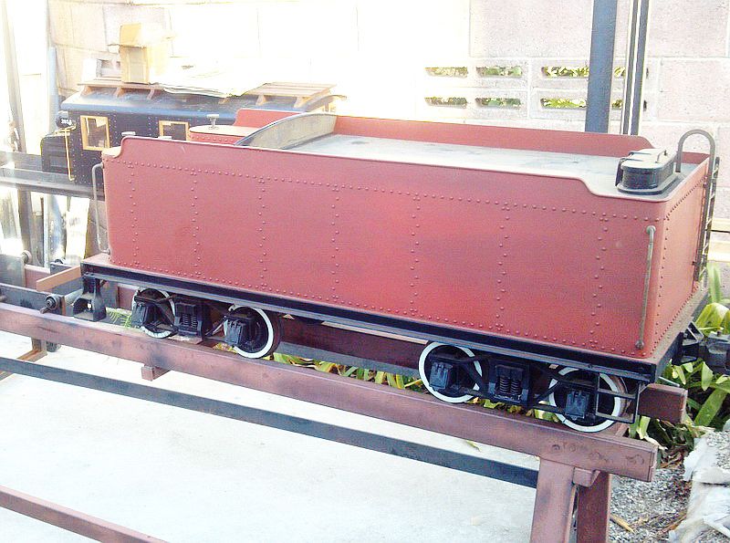
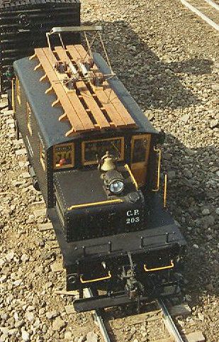
This is the tender I did the rivets on using this device.

Riveting the hoods.

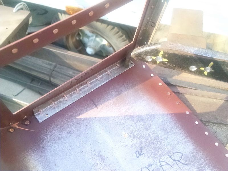
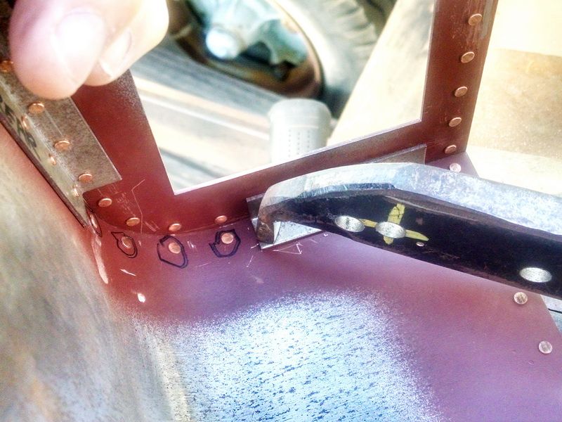
Before we could rivet the hoods together, we had to do the single thickness rivets on the radius of the hood first…we would not be able to rivet these in place once it was assembled. You always have to think ahead so you don’t “paint yourself into a corner”.

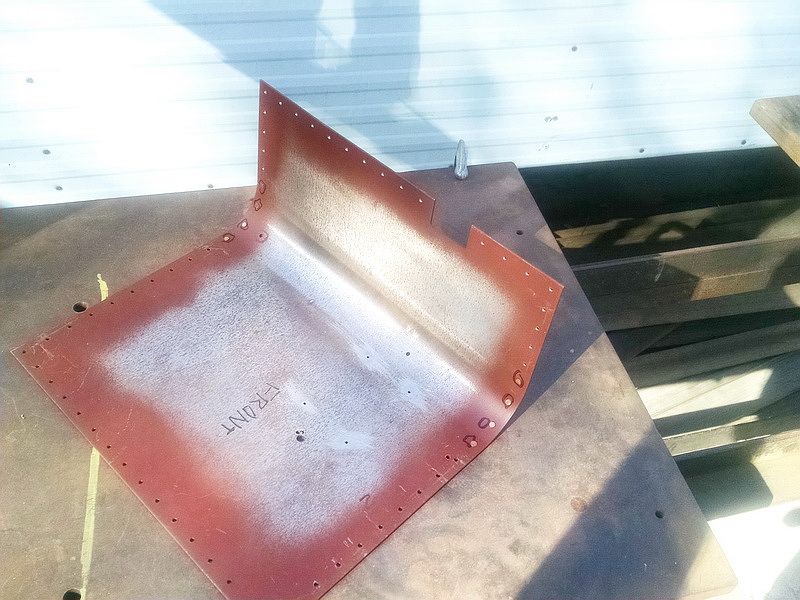
We primered the areas that had rivets in place to prevent rust forming between joints.

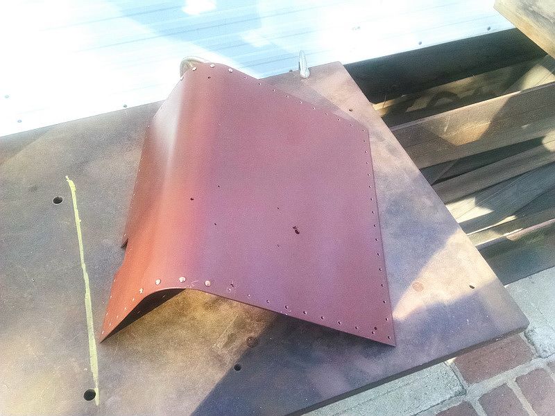
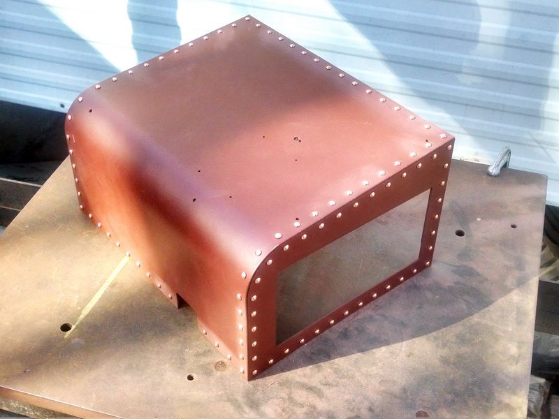
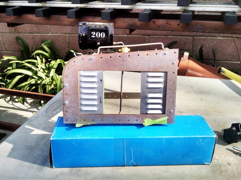
Completed hood. Ready for sanding and prep for finish paint.

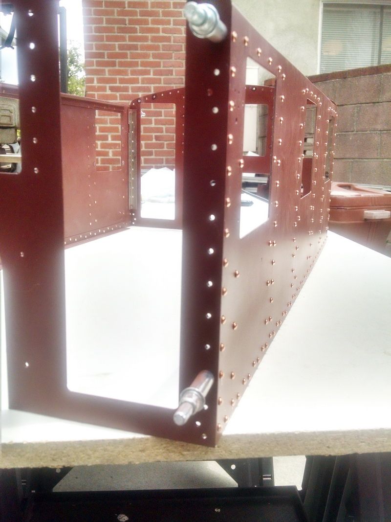
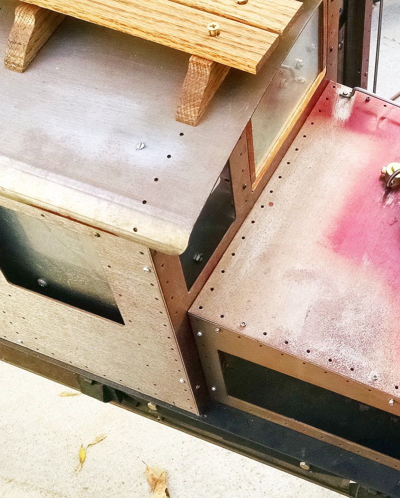
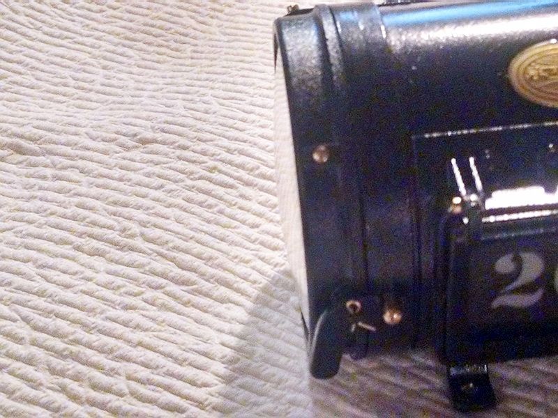
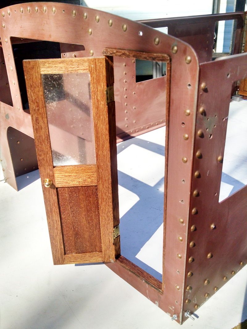
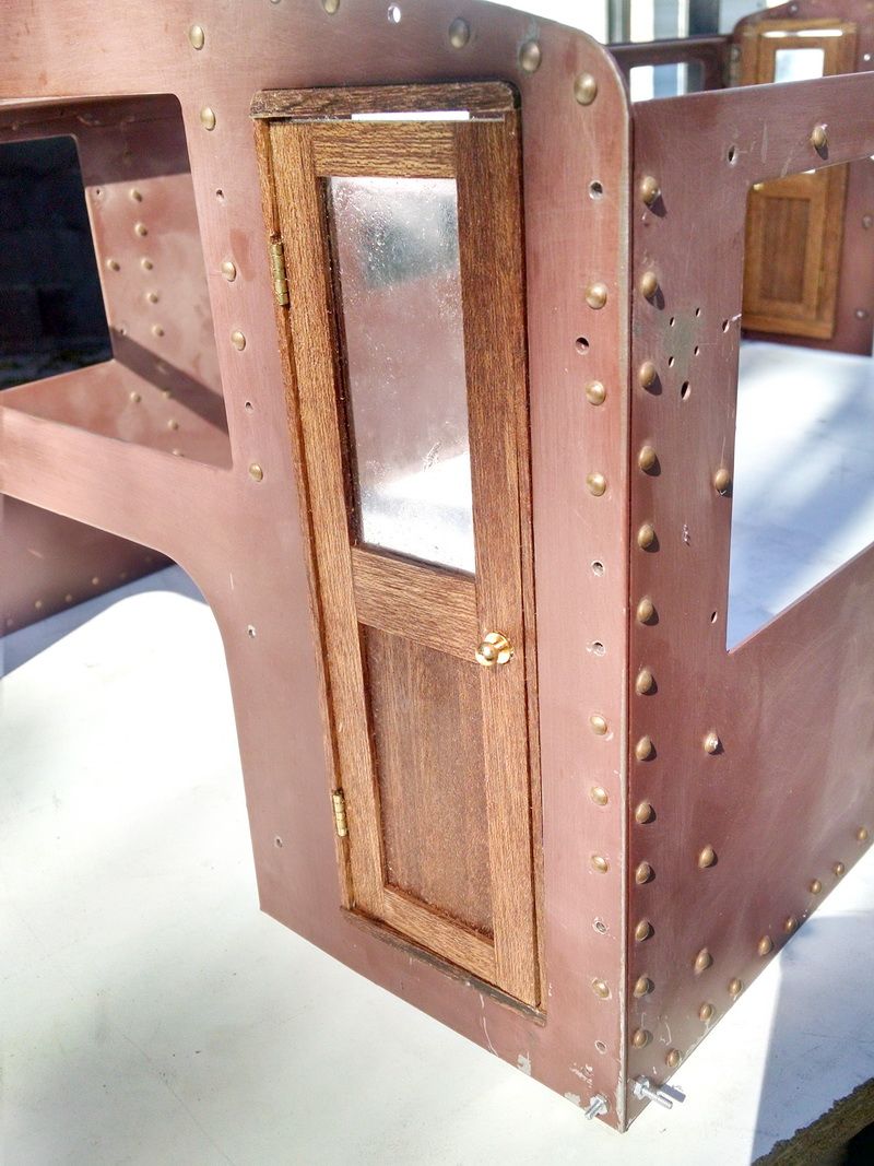
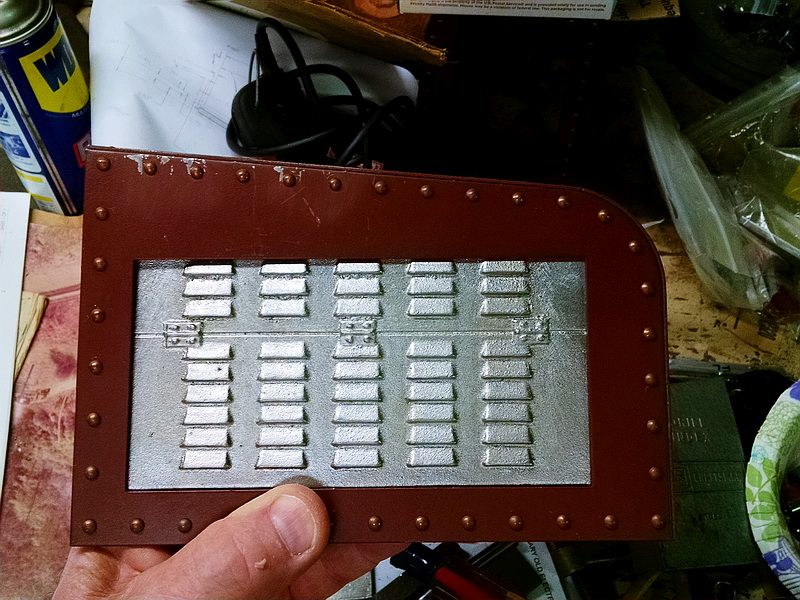
Finish riveted cab end.

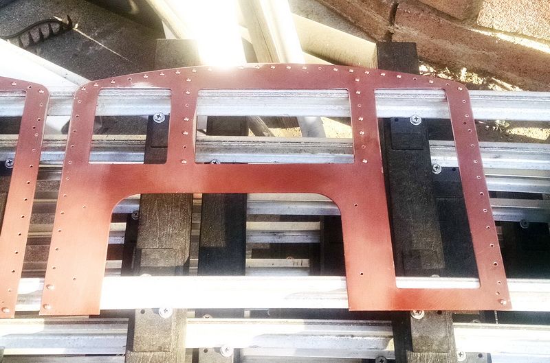
Finish riveted cab side.

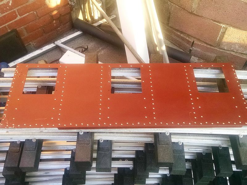
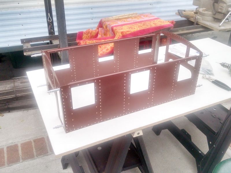
Cab sides and ends assembled to verify all the rivet holes line up. The entire cab was assembled and held with clecos to make sure the rivet holes all lined up. Take note that the holes on the sides and ends are not symmetrical. Left and right hand corner pieces. Had to be careful in these corner areas.

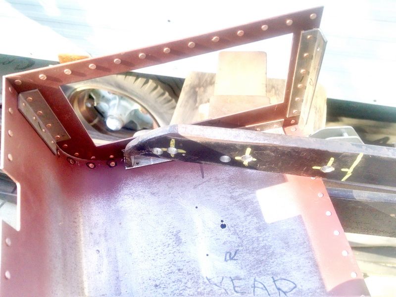
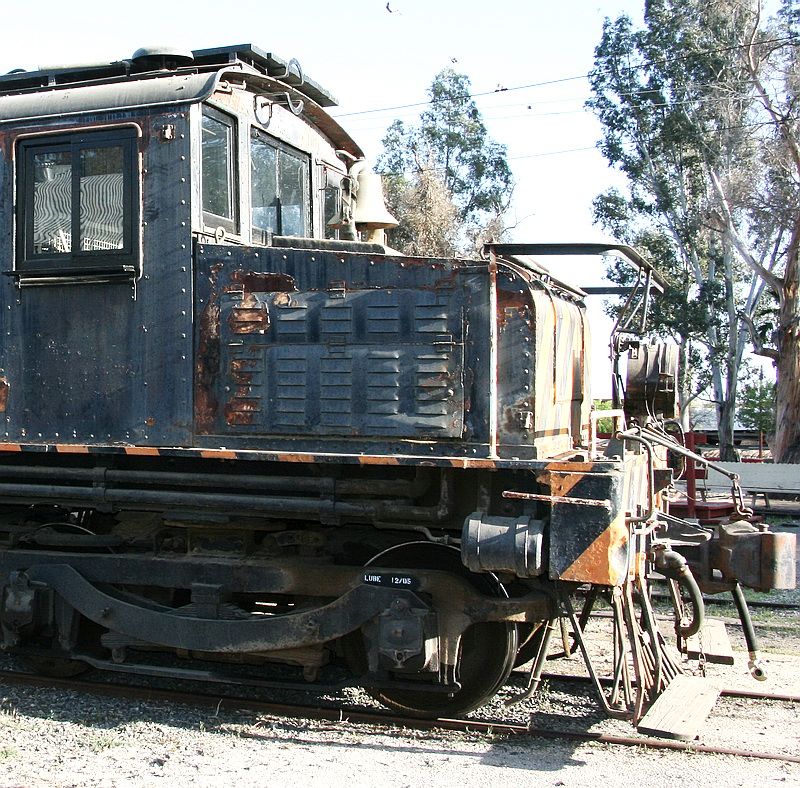
Riveting the roof of this engine had its own “issues”. The arm on the riveting device wasn’t long enough to reach the center rivets of the roof! We HAD to come from the side. Because the roof has the typical “Baldwin Locomotive” curve, we had to tip the roof at various angles to get a nice flat “mash” on each rivet.

So back to the “drawing board”.

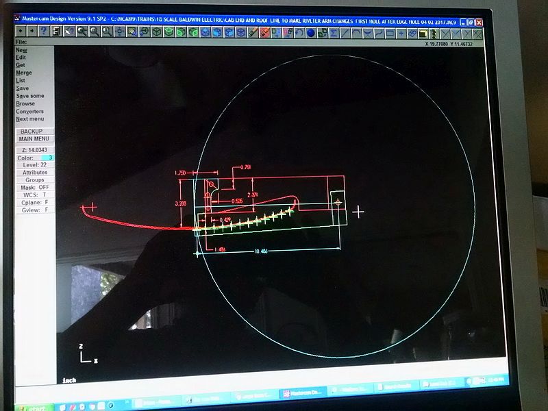
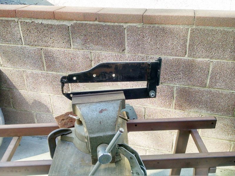
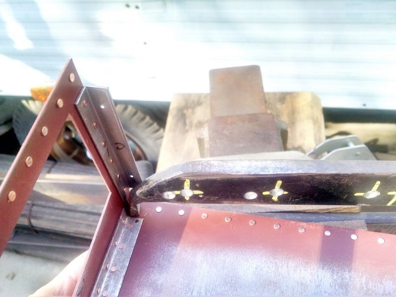
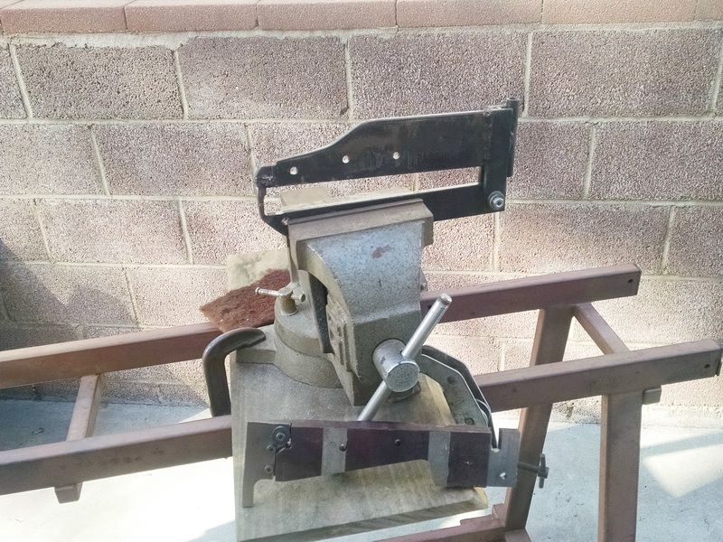
I machined a new arm for the riveter for the roof only.

The new arm is in front of the vice in this photo. We just remove the original arm and replace it with this new one. Note the clearance cut into this arm to clear the roof as it is tipped.

When these metal roof were rolled back in the middle nineties, they were done by CNC control rollers. But these machines were very crude in those days and left marks in the metal as it was rolled. I did a little “bench work” on these anf smoothed things out quite a bit.

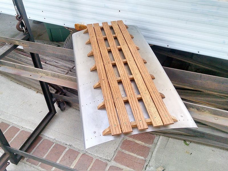
The so-called “marks” along the edge of this finished sanded roof is actually the reflection of our house in the background!

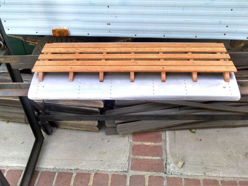
Finish riveted roof and in the process of final sanding for primer and finish coat.

Gary

If you were to fill the tender with water …the rivets are enough or do you solder also?

Sean McGillicuddy said:

Gary

If you were to fill the tender with water …the rivets are enough or do you solder also?

Sean,

No the rivets are not enough to seal the tank. I sold this locomotive last January to a young corporate/private jet pilot. He has this engine now running on air. He keeps me “updated” on his progress. But to answer your question…the top of that tank does lift off to do maintenance and work on the three water valves on the wings of the tank. He will be “fiberglassing” all sides and the bottom. It will essentially become a molded one-piece tank. Holds about 8 gallons of water. There will also be several "baffles installed inside to cut down on the movement of water in the tank. Every live steam engine in this scale (or larger) has baffles to cut down on the “sloshing” of water.

Good memory Gary.

Indeed, I worked at the San Diego Division of HP. This division was still making analog strip chart recorders, instrumentation tape recorders and analog XY plotters.

The division used to be called the Moseley division, and it was basically purchased from Frank L. Moseley.

I don’t remember if he made it to our yearly division meetings, Hewlett and Packard themselves used to visit each division every year for these meetings.

He was quite a guy.

Greg

Greg Elmassian said:

Good memory Gary.

Indeed, I worked at the San Diego Division of HP. This division was still making analog strip chart recorders, instrumentation tape recorders and analog XY plotters.

The division used to be called the Moseley division, and it was basically purchased from Frank L. Moseley.

I don’t remember if he made it to our yearly division meetings, Hewlett and Packard themselves used to visit each division every year for these meetings.

He was quite a guy.

Greg

Greg,

Small world…I don’t know about Frank…I always called him Francis :). After I ordered the generator, he invited up to his home in Flintridge to pick it up. Gave me the tour of his shop. That shop was “to die for”. I got to see the fixtures he used to build the generators…in fact at that time, he was working on building a 1" scale working steam generator. To this day, Francis Moseley is the ONLY one to have built and to market a successful miniature steam generator. The secret was in the making of the turbine blades and the bearings to withstand 50,000 plus RPM! BTW, he had a pretty nice 1" scale railroad going around his home and property.

Back to this “build log” after a couple of months off…

I received the mahogany wood door frames and doors for the cab a couple of weeks ago from our cabinet maker. Mortised miniature butt hinges and brass door knobs.

Door frame and door placed in steel cab.

The window glass has to be cleaned with alcohol as soon as these are installed permanently. The glass is .090 thick safety glass used for picture frames.

Well, a few months have gone by and no updates to this build for a while. We have been busy getting the remaining six cabs riveted. In the meantime, I was doing some research and designing the model louvered panel doors that were installed on the end hoods of these 1600 series locomotives. We were trying to decide if we wanted to have louvered panels made. These louvers were the result of that idea. These were actual louvers, but not to scale. AND we add to attach each panel together to make one large panel door. Bad idea…back to the drawing board and the computer.

Then last May, I saw a company advertisement on Backyard Railroading Facebook site. A small foundry near Kent, Ohio specializing in unusual detail items for 1" and 1-1/2" scale detail castings and 3D printing work. I contacted the owner of Fair Weather Foundry and asked if he was interested in a project. He was and he said to send a photo of the actual louvered doors on a prototype P.E. electric engine and he would see what he could do. I have quite a few photos of the #1624 P.E. freight motor at Orange Empire Trolley Museum here in So. California. I found a photo and sent it off to him.

This is the photo and the closeup of the louvered doors.

AND the closeup…

I had my answer overnight! He took the photograph and embedded it in AutoDesk Fusion 360 software. I think many of us use this software to do 3D printing here on LSC. The photos below show how the photo became an actual mold for a sand casting in aluminum!

From this Fusion 360 drawing, the foundry 3D printed the master model for the sand mold casting. Took one hour to “print” the master. He did some finish work to get rid of the tool marks and pressed the master into the sand.

These are the results and the finish aluminjum castings. The crazy thing is that the technology was so fluid throughout the process. No charge to print the mold and $15 each for the castings!

We have to do some milling around the raised area of the casting so it will fit the existing opening in our hoods.

This was the first casting and hjad some blow holes and fall away of the sand. He sent this along for checking dimensions. All in all, it was a great experiment. It opens up a whole new world in making EXACT castings from any photograph!

Gary,

Thanks for sharing. That is so cool! Technology seems to be changing everything.

Finally after finishing the scratch-build of the 1-1/2 inch scale #5 turnout in 7-1/2 inch gauge (took way too long to build that thing!), I got back to work on my two Baldwin P.E. boxcab electrics. Both the 35 yr. old engine and it’s brand new sister have had design changes throughout the build. One thing we always wanted to be able to do is to remove the heavy steel cabs when we wanted to work on the electronics or recharge the twin batteries after a long run. In the original design of these electrics done by West Valley Live Steamers in the Bay Area near San Francisco. They used huge steel clips in the four corners of the cab to center the cab on the .090’ thick plate. The weight of the cab held it down to the deck. But once you added all the electronics and wiring, it was difficult to drop the cab into place (especially at night). I did a little design drawing to come up with a more efficient way to easily locate and stilll hold the cabs snug so there was no rattling when running.

When I had a design, I started to make these on the mill. I used 1X1 aluminum angle and 1/4 inch thick aluminum plate. The photo below shows the design. Two 2/56 Allen head cap screws and nuts hold the 1/4 inch plate aluminum in the 1X1 alum angle stock. As a comparison of size, the slot in the aluminum is .060 wide (the material in the cab is .055 thick steel plate. You can see where the large steel clips were originally located and how much smaller the new locators are. It was a very tight squeeze to be about to use the tap drill for the tap for a 6/32 screw. I just didn’t feel moving the instrument panel to get the extra room I needed. I used a Craftsman flexible shaft rotary tool to drill for the tap size. Still wasn’t that much room to work. Even in this large scale, you can still have tight areas to work in. The hole for the 6/32 tap is .106".

I used the locator block as a “guide” to keep the tap vertical and square. I had to clear one corner of the block so it would miss the two wires going through the deck and supplying electrical power to a small ditch light that shows the trucks at night. These come on with the headlights.

One locator block in place and install complete.

One new block installed on the left with one of the original steel clips still showing on the right. That comes out tomorrow and then the old engine is upgraded.

This shot shows the completed new blocks at the front of the cab. you can see how the cab steel fits right down into the small slot. You might be wondering why the cleco clamp shows in the photo…well the hoods are fastened to the cab ends with four 8/32 bolts and nuts. But I had to have a way to remove the screws once the cab was in place (using the old steel clip to keep everything aligned. But there was just not enough room for my fingers to constantly be putting the screws in and thing taking them out every time I wanted to mark the new locations for the alum blocks. Quick way to solve that was to use two cleco clamps…easy on, easy off.

In this final shot, you can see how difficult it is to get access to this block.

That’s all for tonight. One more to add tomorrow and this engine is done. Windows are all in place along with the two engineer doors. I DID order and recived two full sets of decals from our friend Stan Cedarleaf. Custom sheets for cab numbers, hood numbers and reporting marks made to P.E. standards. Thanks Stan. :slight_smile:

You crafty devil you …

Working on our Pacific Electric Baldwin/Westinghouse electric box cabs again.

The P.E. pneumatic trolley pole used on these engines were first introduced by P.E. about a hundred years ago for these box cab freight locos. They proved to be very successful, so they were used on their interurban passenger cars as well up and until P.E. ceased operations here in Southern California in the mid 60’s. I always had trouble researching these poles because any photos taken of them was always taken far away and never any detail. No dimensions either. I finally found a member of Orange Empire Trolley Museum in Perris, CA who offered to get me all the photos I needed and dimensions to actually model one of these.

So after compiling all the photos and dimensions and studying how many parts it took to make one, I started doing drawings in MasterCam. As you can see from this closeup photo, the assembly was fairly complicated at “first look”. As you can see from this first photo, they were always taken from far away and no real detail to work from.

Then I got photos like the one below with all kinds of detail. With the dimensions that I received, it was easy to break down the parts and start the drawings.

This is the drawing I finally came up with…the separate parts are on various “levels” so that I can break down each piece and have it assembled in the correct position. There are about 170–175 different levels in this drawing! Each part is surfaced and filleted just like the steel castings on the prototype and the photo. More screenshots of the drawing below.

This drawing is shown with all the parametric surfaces in place with shading turned ON.

This is the same drawing with the shading turned OFF.

This is the same drawing except that THIS is a solid body now. If some of you have 3D printed parts using Fusion 360 or some other software to generate 3D printer tool paths, then you probably understand the difference. Most, if not all 3D printers will only accept solid models. The great thing about MasterCam is that I made the solid body from the surfaces only. I didn’t have to produce the solid body in Fusion 360. Big time saver! I can now import this solid body INTO Fusion 360 directly as a file converted to IGES. Saves a lot of converting of files for Shapeways, etc.

This screenshot shows the solid body after I imported to my MacBook Pro. I can now manipulate the drawing in this software for 3D printing. Because Fusion 360 runs in the “Cloud”, Nothing is actually saved on my computer. The great thing about using the cloud is that the man who be doing the molds for these parts, has access to my drawings to do his “thing”. As soon as he makes a design change or wants to discuss certain parts of the molds, I can see these changes on my MacBook in real time. Technology is so cool now for the hobbyist. BTW, Fusion 360 can be used for free from Desktop just by saying you are a “hobbyist” or starup business making less than $100K per year. You just renew the software access license each year by clicking a button on the software. You have full access to tech supoort and all turorials that are available. Great system. AND Fusion 360 now has full CAM capability to generate tool paths on a CNC mill or lathe. Same tool paths that I have on my $15K MasterCam seat. The cost of Fusion 360 is $495 per year otherwise.

I’m waiting on my foundry guy to take a olook at these first two castings for the trolley pole. I have quite a few more parts in the drawing to make the surfaces “watertight” and then generate the solid bodies for the next few molds. All the parts will be cast 6061 aluminum and fastened together with scale micro fasteners hex head bolts and nuts. Most of the bolts will be 0-80, 1-72 or 2-56.

Looks safe to say that this thread qualifies as informative and educational.

Very cool stuff Gary, your ability using those programs astounds me. Just out of curiosity how does riding behind that locomotive work out with that trolley poll sticking back in your face?